With zero voltage between the two diagonal pins pictured in the first picture here Shapeoko 5 pro and vfd spindle issues - #118 by Gibs
Does the VFD controller look like my pictures or like atreides pictures?
Are you referring to this picture? Shapeoko 5 pro and vfd spindle issues - #98 by atreides
I’ll need to crack it open and see… struggling to think this is VFD related unless some earlier rev doesn’t play well with the new shapeoko controller?
I’m also getting a periodic initialization failure about failing to back off some limit switch. Sounds unrelated but only started happening today too.
Yeah, doesn’t sound VFD related if you are not getting 24V between red and black. The earlier versions of the VFD controller can fail in a way that makes them unresponsive to the PWM signals from the SO5 controller.
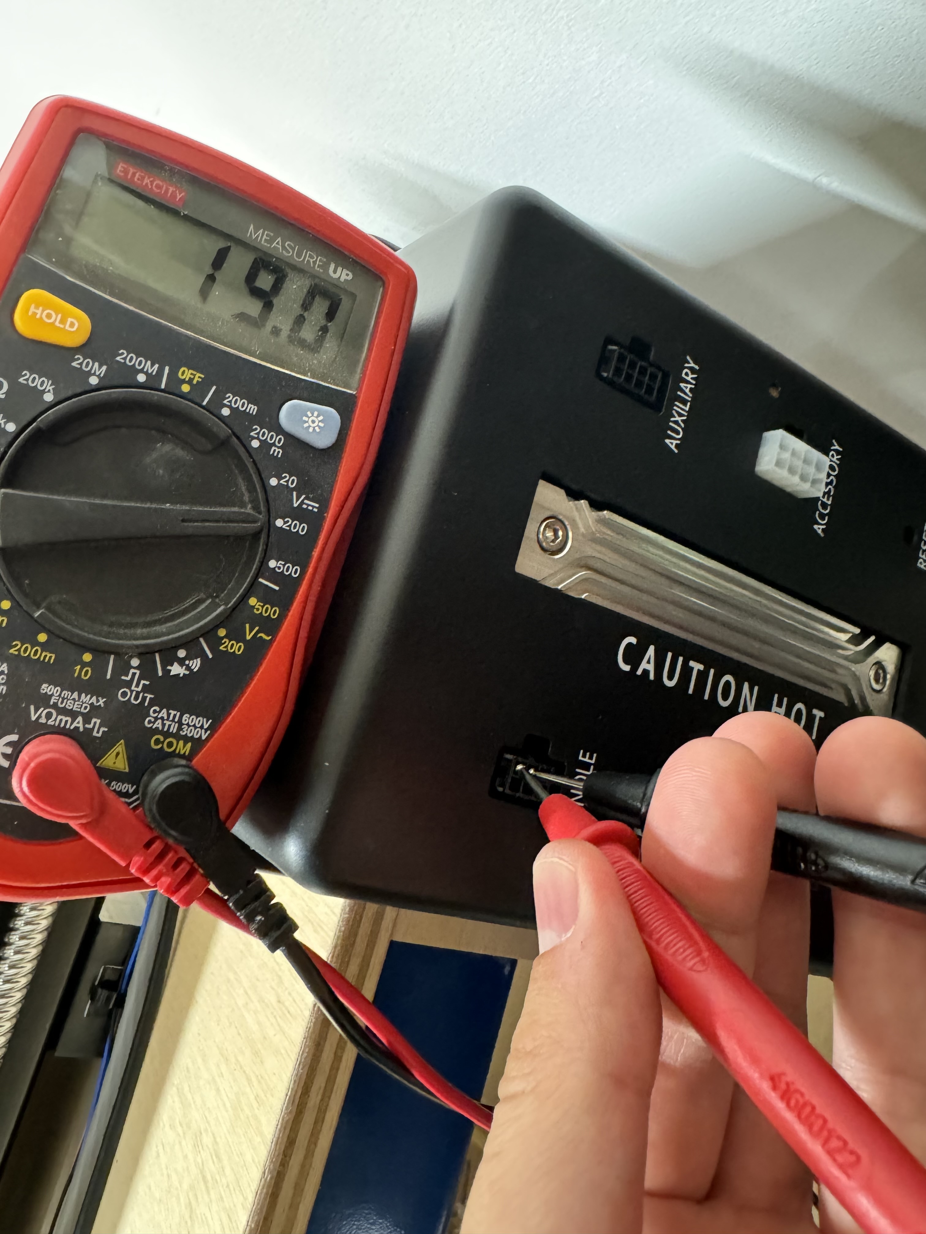
Are you saying that you get 0v between red and black until you request 24k RPM? Then it is 19V?
Sorry, let me back up a bit since I just went and reprobed everything with a different multimeter setting and am no longer seeing any 0v. (Noob at this)
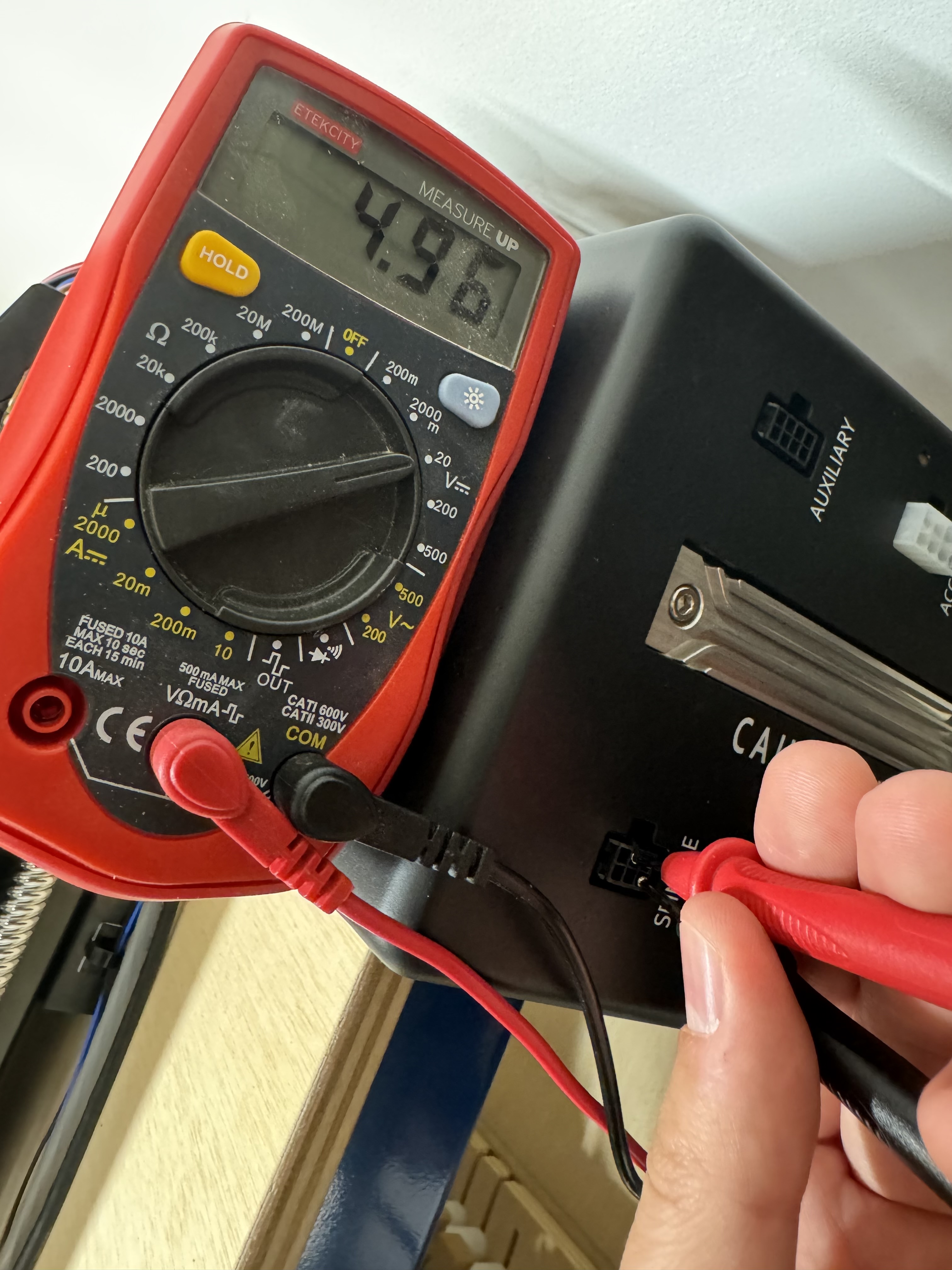
These are my readings:
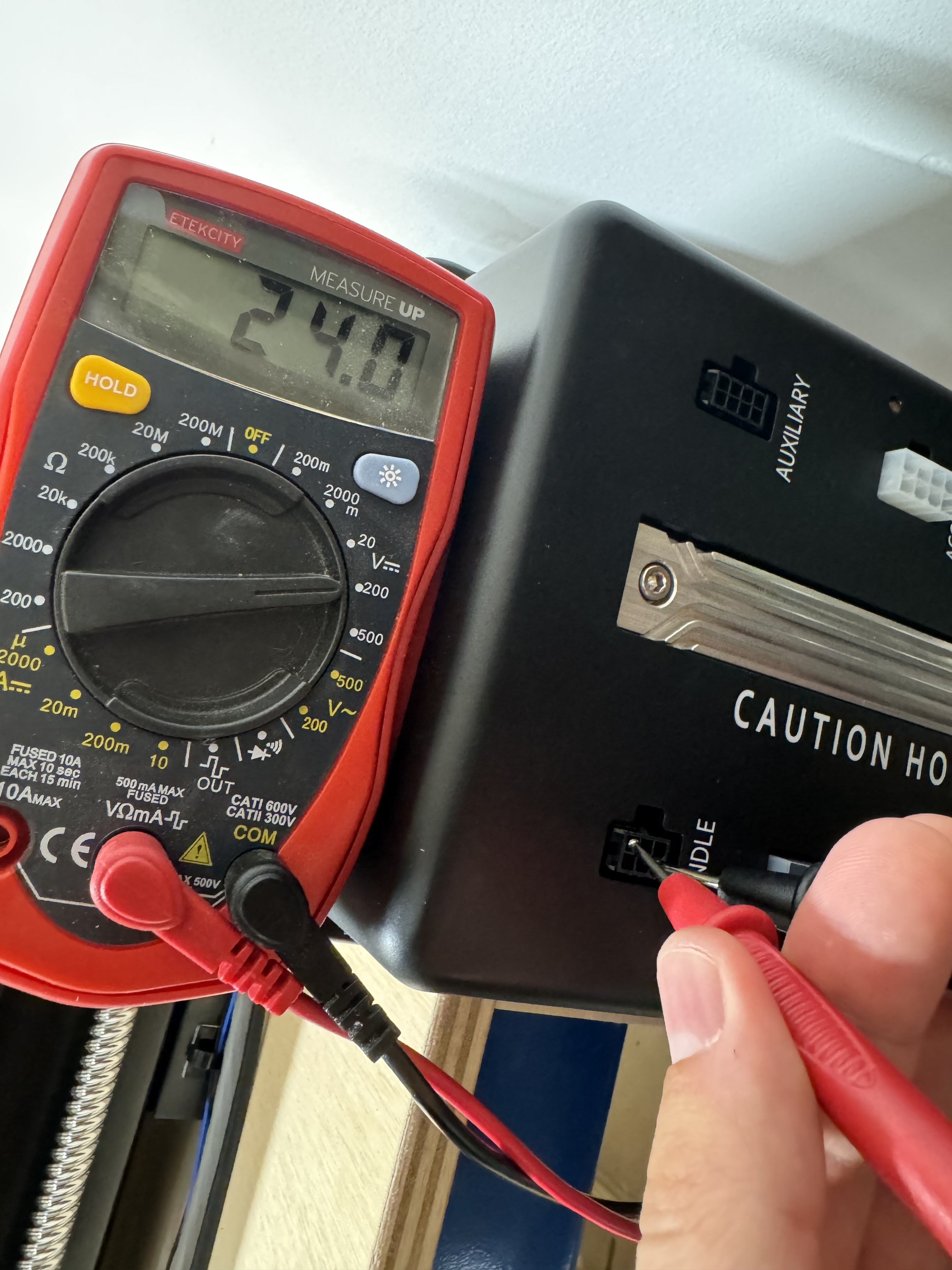
Took another look at the VFD and the armed light is 100% more dim than it was in the past.
That’s after a M3S24000.
Okay those probe readings along with what you just said about the light make me think that you might have a bad VFD controller. 19V between red and white when requesting 24k is normal because 24V-5V=19V.
You might want to crack open your VFD and see if you have a modified controller board or not. Also even though it is not spinning up do you see the Hz reading on the display change from 0? Probably low numbers flickering.
1 Like
Thanks - no, the reading on the VFD is flashing 0.00. I’ll start taking it apart. If I don’t reply I touched a charged capacitor.
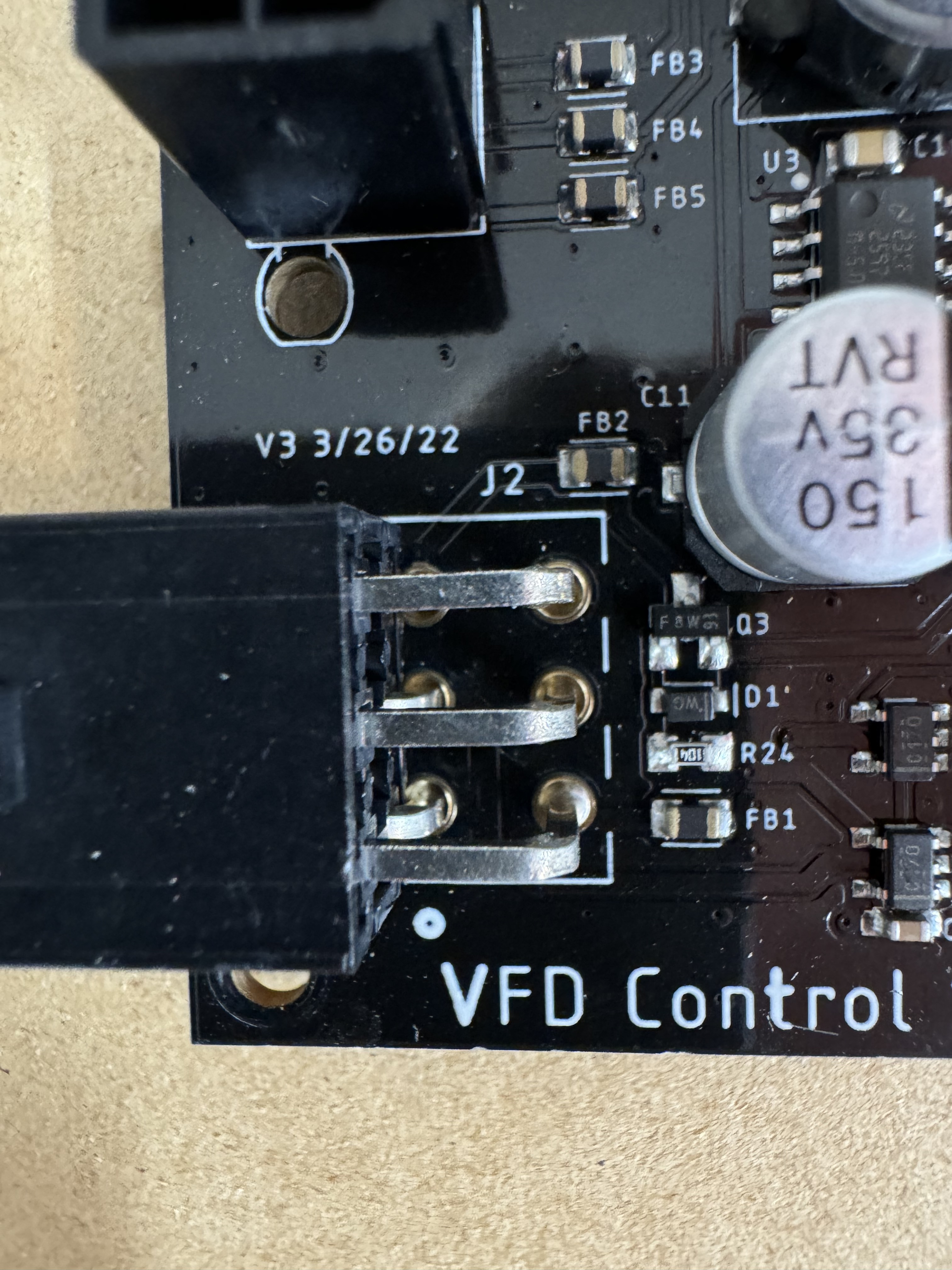
Uhhh… opened up the side and the yellow wire was totally pinched and has a path to ground. Is that intentional? In an effort to not disassemble further… can you see what you’re looking for from this picture?
Doesn’t look like it was hand modified like some other pictures.
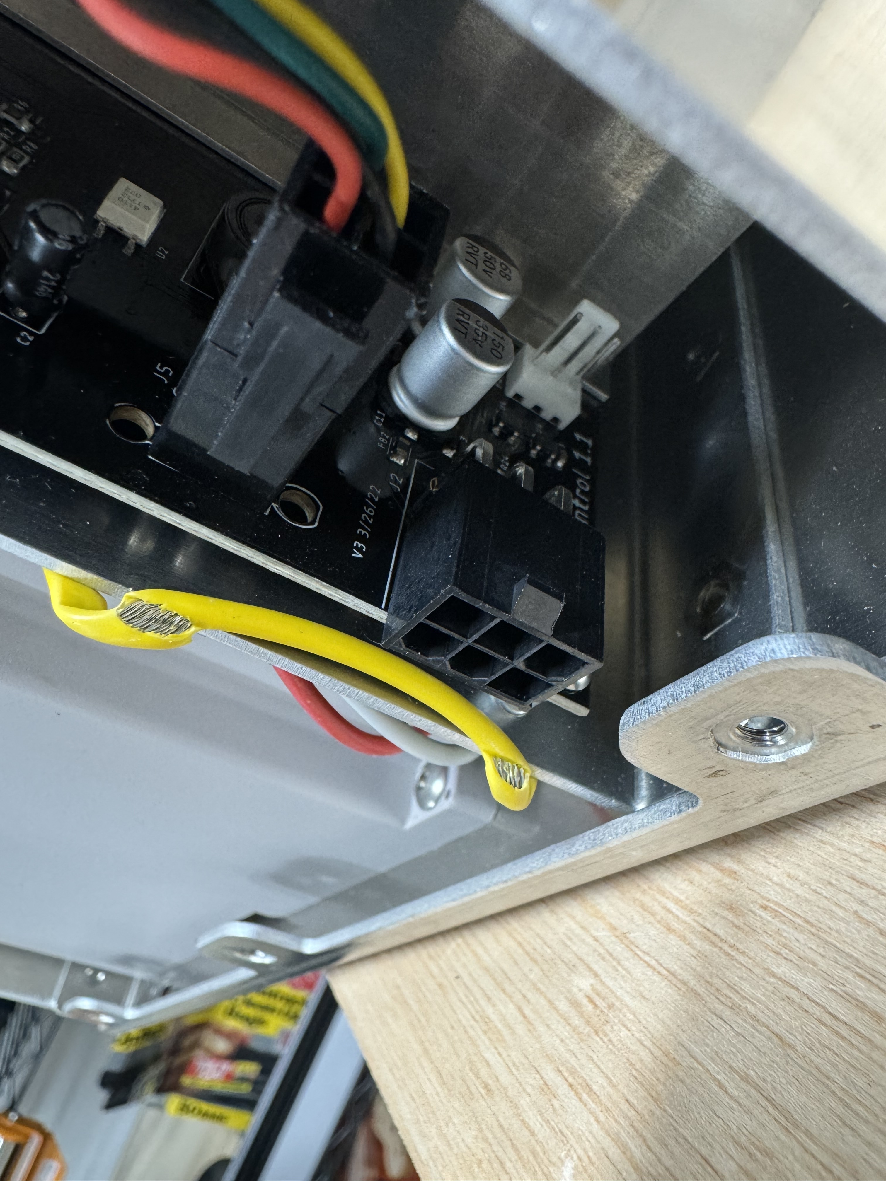
As someone who formerly worked in the electronics industry, I can say with near full confidence that the yellow wire should not look like that. ![]()
3 Likes
The connector is right in the way of what I’m trying to see. I just want to know if they modified the component in Q3’s spot. And no that yellow wire should not be pinched. That wire looks like it is either ground or L1 a hot wire(they color coded both yellow).
Couldn’t get the camera back there - but nothing behind that connector had any hints of being manually soldered.
Also - would you expect I get continuity to ground between the pin where the black wire goes and the housing? I don’t get ground from any pin.
From everything you have mentioned here then it sounds like you have a bad VFD controller. The biggest give away is the dim led light on the push button.
I no longer believe you are supposed to have continuity between the black wire going to the VFD and chassis. I believe some units have low resistance due to the fact that there is ground pour where the mounting screws go but I also believe this was a mistake by the engineer who deigned the board. The mains side of the board has a pad with no solder mask that shows intentional grounding of the EMI shield where as the other mounting screw locations do not.
2 Likes
Thanks a ton for the back and forth @Gibs. I’ve got an open support case and will push for a new VFD controller.
1 Like
What other machine did you have your eye on?
Support is sending a new controller board for the VFD. I’ll update this thread with the results…
1 Like
@Gibs Got the board out in preparation for the new one. Following up on that picture.
Also, the pinched yellow wire was indeed ground… so I guess getting pinched against the case isn’t the end of the world ![]()
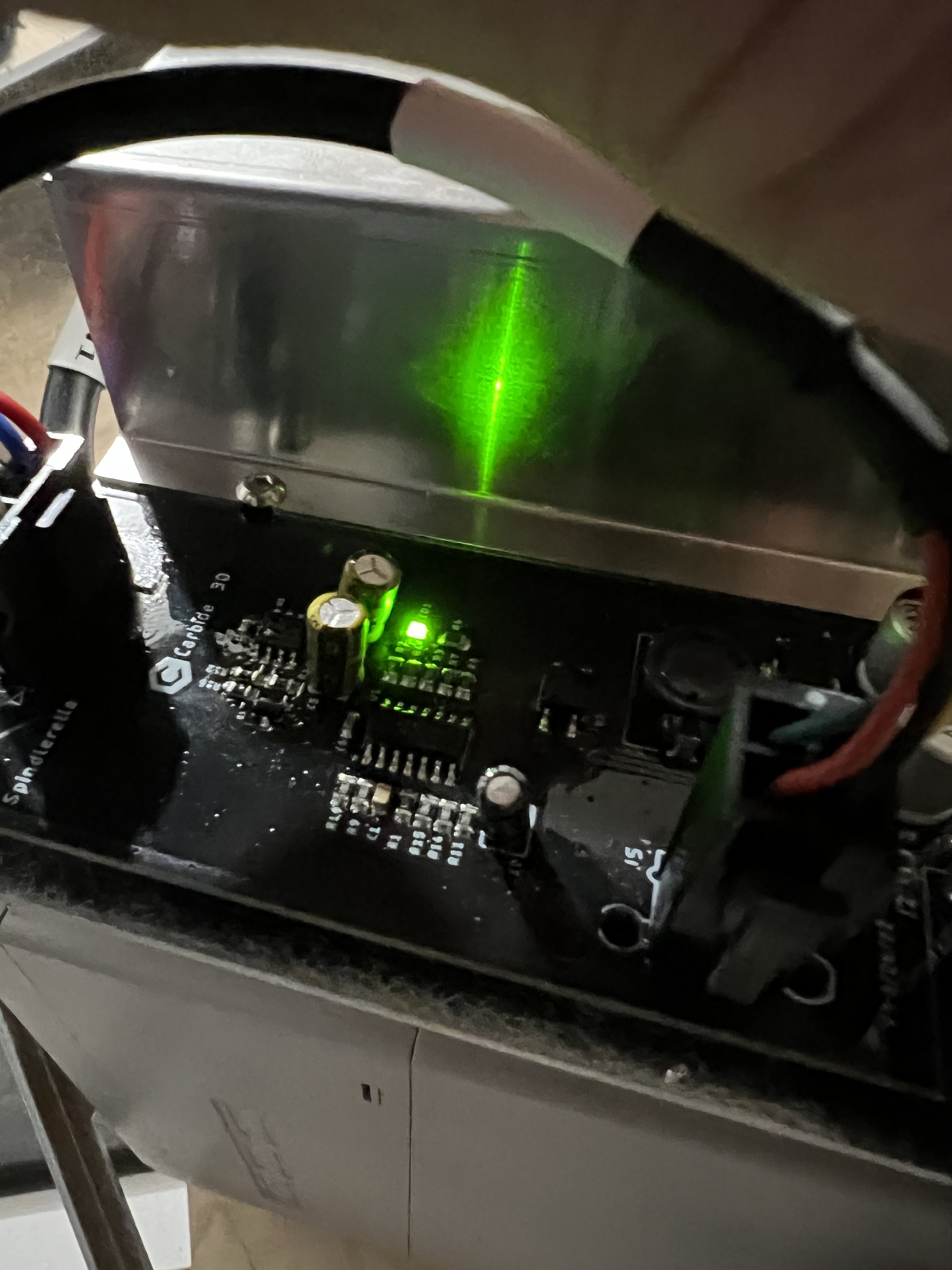
I have found a better test for confirming the VFD control board is bad. With everything plugged in and the SO5 turned on you should get a green LED light on the VFD control board. If you do not get the light then your VFD control board is bad since we already confirmed you have 24V coming from the SO5.

1 Like
And that’s without sending any M3 commands, right?
Yeah the light should come on just from the +24v provided by the SO5 when the SO5 is powered on.
New SO5 controller shipping today. So hopefully I have everything fully functional this weekend!
2 Likes