Copy with pride. my table is an imitation of designs all over the internet. The dust sucker attachment is my innovation.
I received my 5 pro 11/24 and have spent the last few days shaking it down and getting to know the machine.
With the amount of weight the machine is slinging around, the table shakes a bit. I may screw a few diagonals to the frame to see if that stiffens it up. I expect I will mount a bracket on the wall so that I can lock the table down when I do not need access to the rear.
Rolling the table around on the 3" pvc casters is pretty easy. But my floor is not yet covered with random cut-offs.
In a couple of days, I’ll complete some in-process projects, and will be able to start assembling the cabinet over the machine.
I am planning a frame similar to the table frame with removable 1/4 ply panels on the sides and top lined with 3/4 foam. The front will have doors hinged at the sides with acrylic or lexan windows. The rear will have doors hinged at the top and bottom (no windows) which will allow me access to the rear for maintenance or to run stock longer than the machine bed.
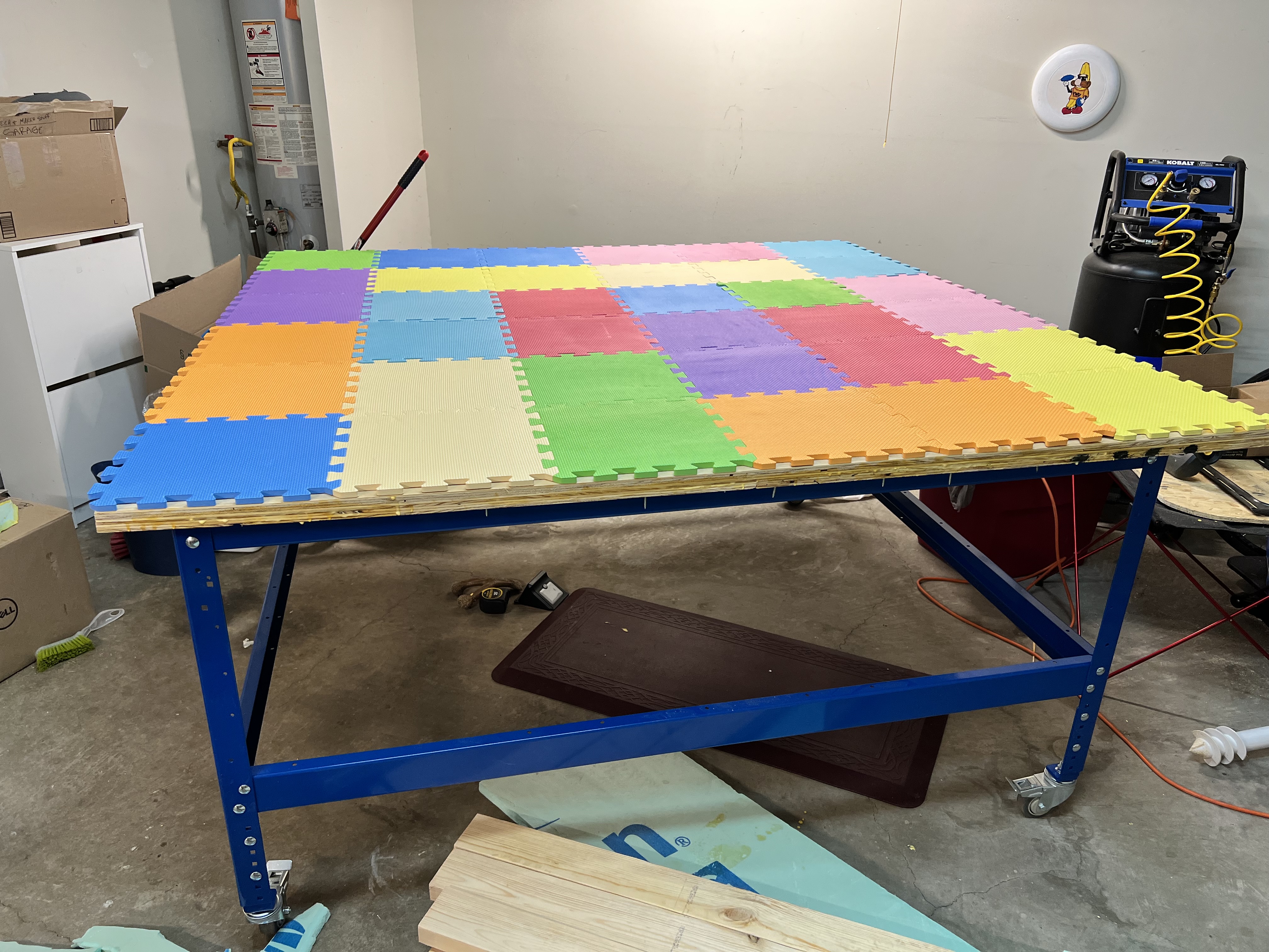
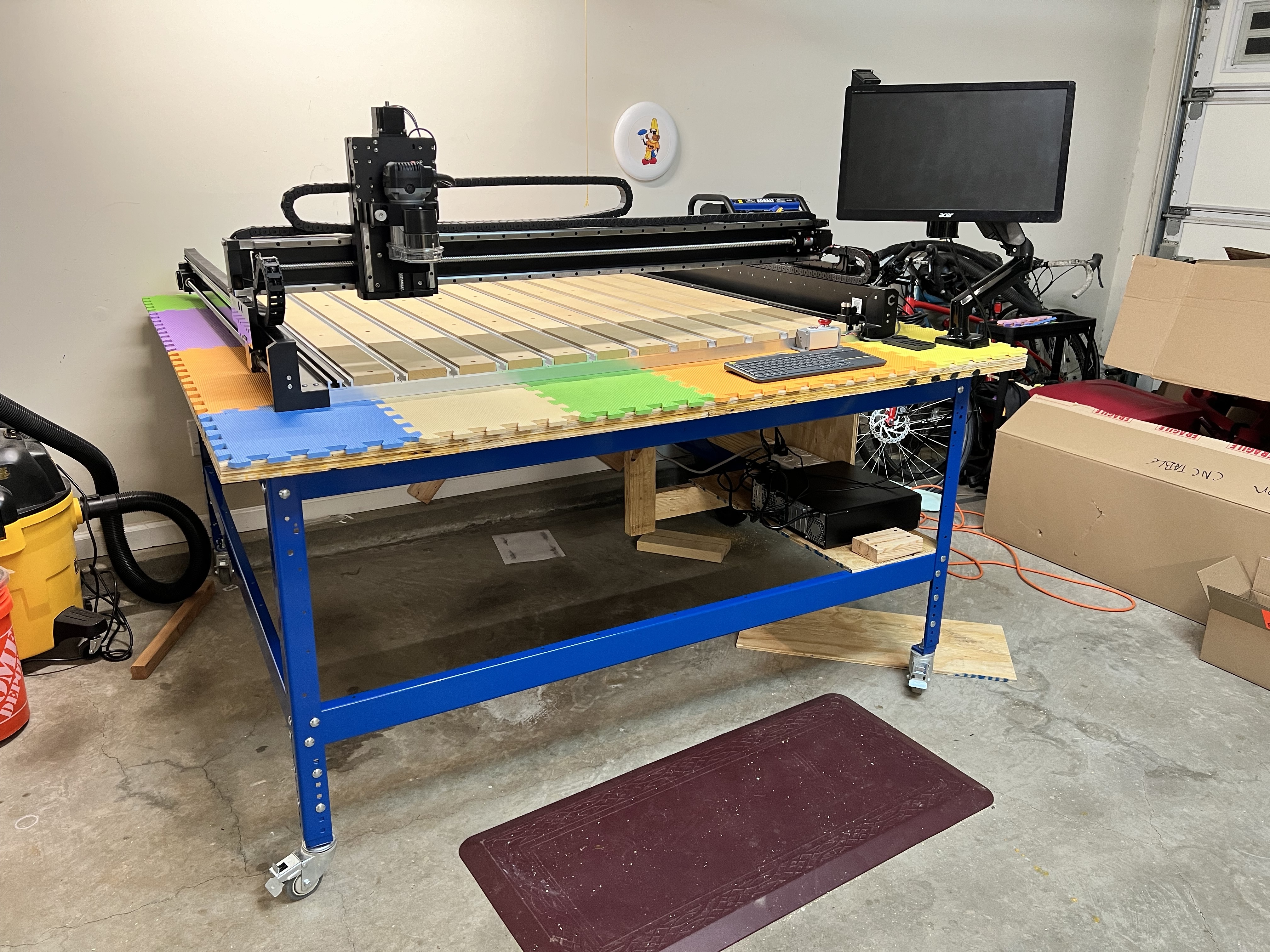
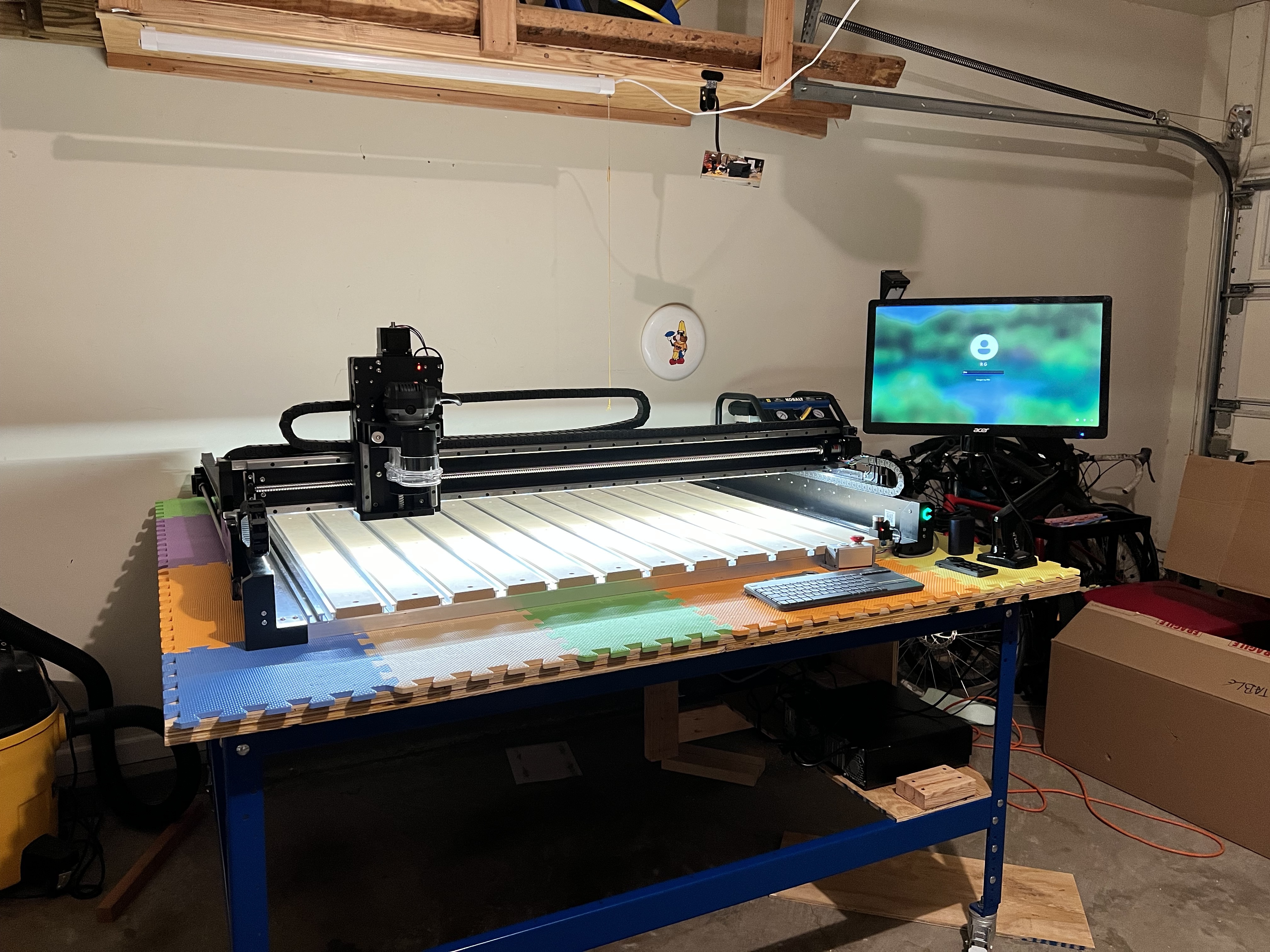
An update on my setup! Over the last week or so a few more of my boxes came in, and tonight I just finished building the table and table top. I need to attach it, but it’s 99% ready for the machine. I decided to go with the Kreg table. While a wooden table would possible cost less in the beginning, it would end up costing more in time spent designing, planning, and building. Now my table is done, and my machine should ship next week (hopefully).
I added some foam mats for decoupling and they fit my 70x70” table exactly! Couldn’t be happier about that. Also, I chose the colorful ones because I’m getting a little bored with everything being black or gray.
next is figuring 1) how to put my shop vac under there so it’ll move nicely, and 2) how to put the cyclone under there. With all the hoses it keeps falling over.
For the past few months I have been doing prototype work at my job using a 80W CO2 laser and my Shapeoko 3. It has been working alright but I kept running into size restrictions. When the Black Friday deals came around my boss decided it was time to spring for a better CNC and got the Shapeoko 5 Pro 4x4. His one stipulation was that it needed to be in a more sound proof enclosure than the one I made for my Shapeoko 3 years ago. So began my new enclosure journey.
Now our machine is not going to ship for a week or two do to Carbide3D’s back log which is fine and I do not want to finalize the enclosure’s design until we have it here. That does not mean though that I cannot get the base put together first:
The ratcheting lever makes raising and lowering them much easier than others I have used before.
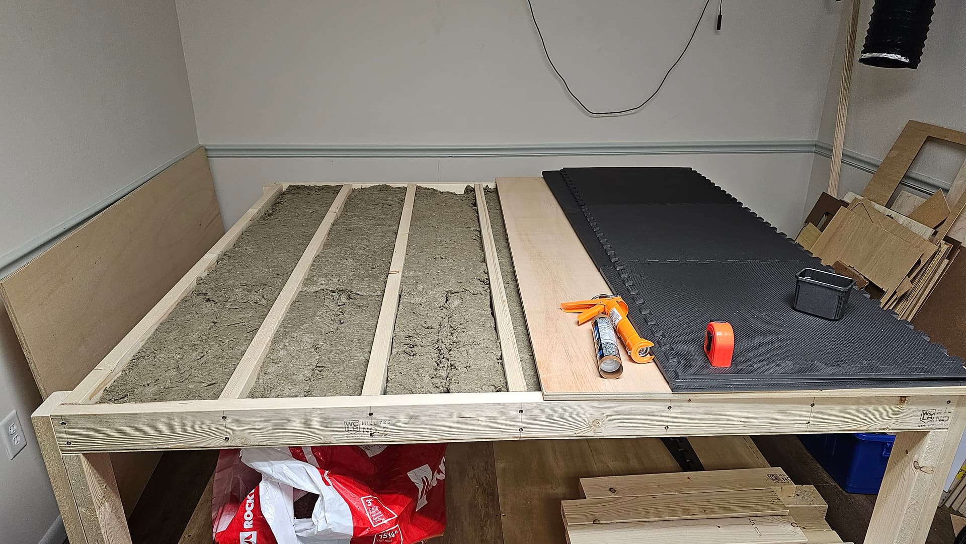
The table top is 72" by 72" and is supported by 2x4’s 11" on center. The voids between the “studs” for lack of a better term are filled with Rockwool Safe and Sound insulation. The plywood on the top and bottom of the table top is siliconed down. On top of that will be a layer of EVA foam that the 5 Pro will sit on.
@DanWorks Is that the 5 Pro? I’m still waiting on mine (Pro 5 2x4) to ship but trying to think ahead while I have time. What is the dimensions of the rolling table you built? What you have is pretty close to what I’m thinking of going with at first. It will all be put together in a way that I can take it apart to modify when needed.
Any lessons learned that you can think of that you could pass along?
I thought I’d post an update on the table I posted on October 22.
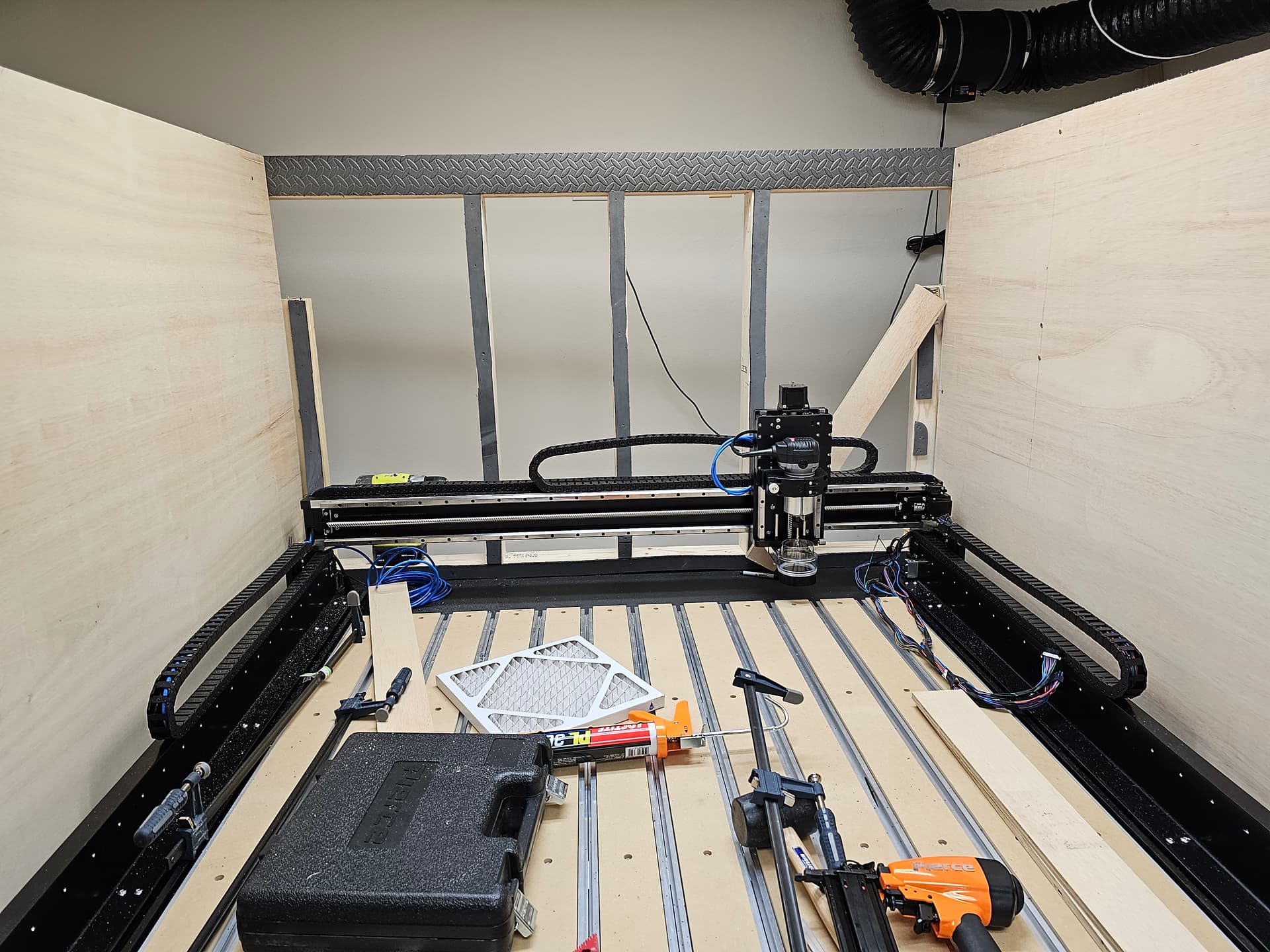
I received my machine on 11/25, assembled it, tested it, then started working on the enclosure.
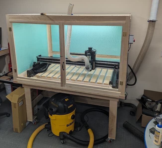
it’s about done now, still have to do a little vacuum plumbing and figure out where to put the computer (maybe on a stand attached to one corner). I am not trying for silent here. I want to manage dust and take the edge off the noise.
The exterior dimensions of the box are 66" wide x 46.5 deep x 40" tall on a 34" table. That puts the bottom of the header across the front doors at 71" above the floor, 1" above my head.
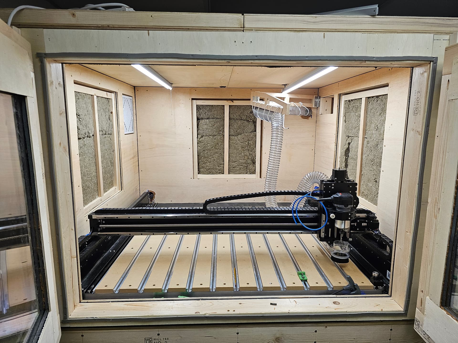
The cabinet is framed with 3/4" birch plywood, similar to the table construction.
I hung 1/4" ply on the frame to make the sides and top. The green stuff is 3/4" insulating foam glued to the 1/4 ply to absorb sound and dampen vibration. The sides are screwed on and can be removed if necessary.
The front doors are plywood framing with .093" acrylic panes. Yes, polycarbonate would be better. There is a 1/2" inch gap between the bottom of the doors and the 2" sill (right at machine table height). Air will be drawn in through that gap, across the table, and down through the table into the dust collection system (see my october 22 pictures above)
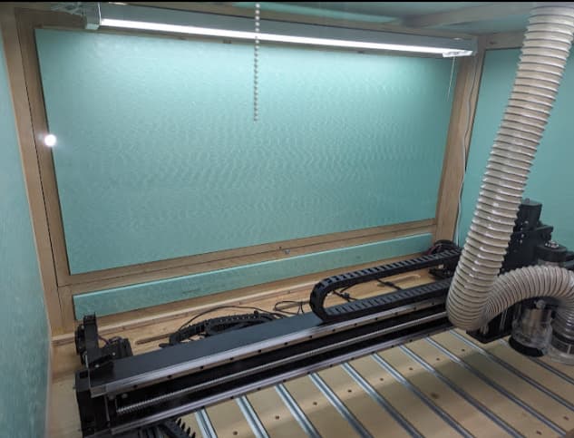
The rear has doors as well. The bottom 6" swing down in case I ever want to put long stock through the machine. The upper panel is hinged at the top, allowing me to swing it up for access to the rear.
The hose from the roof to the sweepy will either tie into the dust collection or the shop vac. Experiments upcoming.
I had a couple of spare 4’ LED shop lights, so they went into the box too.
Well, “Billy” is here, and assembled as of last night! I was planning on doing my initializing and setup today, but I got a ping that my VFD would be delivered today, so I’ll set that up and do first tests tomorrow! Very excited!
I used Kingspan Insulation R-3.75, 0.75-in x 4-ft x 8-ft Unfaced Foam Board Insulation from Lowes. The pink Owens-Corning stuff would work the same, but my local Lowes is much closer than Home Depot.
I wanted a hard surface on the insulation so that dust would be easy to brush off.
I do like your foam squares. I’ll see how much vibration I get through the table, then maybe do similar.
I’m in limbo right now waiting for a replacement VFD spindle adaptor cable from C3D. The first replacement got lost in US mail. The 2nd attempt is on a 5 day (fedex tracking estimate) wander from Moline, IL to Detroit, MI via FedEx 2Day. That’s a 6 hour drive for normal people.
I think I’ll put a trim router on the machine for a few days. I have gcode written for a John Clark cube, a simple 6 sided 3D job in cad, and an inlay project in planning.
I’m waiting on my 4x2 to be delivered and have been building my enclosure in the meantime. One of the questions I have for those that already have them is, how long is the cables for the controller to the machine? I want to make sure that I have a good mounting point for it that won’t stretch the cables too far but also allows good access to it as needed. And in a lot of pictures I’ve looked at, it seems that the controller is on the right side of the machine, but I see a lot of VFD controllers on the left sides. While I would like to co-locate everything, I’m guessing there is a reason for the VFD to be in a different spot?
I just assembled my 4x4 machine. The wiring harness has about 36" between the back right corner of the machine to the connectors. I am assuming that is the same for the 4x2.
As for the VFD the reason that people have it on the other side is because the drag chain for the spindle / router cord terminates at the back left of the machine.
Just in case anyone was wondering, I think all three of these would “work”.
Link # 3 (with the acrylic) I wouldn’t trust to install the drivers. I couldn’t find a good download site for them, aside from a google drive or dropbox link… Apparently though it’s a semi-rare board, and some work has been done to make compatible software. Going to tuck it away for a rainy day.
Links 2 & 1 are both pretty solid, but I decided on the Huion (Link 1) for the layout options.
I say they “work” because I can’t get a consistent operation at fast, and not every button press results in movement… CM says “busy”. not sure what that’s about. if anyone has tips, I’d appreciate it!
@CthulhuLabs is correct. instructions have you running the cable for the VFD on the left side.
I presume you could run it down the right side of the machine, but I don’t know if that would affect anything. i know running power and data cables parallel may cause issues, but I don’t know if that would cause a problem here. if not, I’d like to know.
My (temporary) setup is like what you’ve seen though: VFD controller on left, Shapeoko on the right. If you wanted to co-locate them, I imagine you could put them on the rear of the machine at the back. The controller has a bit more length to play with, depending on where your computer/usb cable has to reach to.
Dang though… I just remembered my power pendent can barely reach to the front of the machine with where the controller is… so I guess thats the limiting factor. Bit of a stream of consciousness.
Another thought on this: you can locate all the boxes where they need to go, but put some kind of switch on the plug. Leave the power switch on the unit on, but re-locate the switch to the front of the machine. Then all it’d take is confirming the power has gone on. I might do a smart plug based switch option, but recently my smart home has been dragging… I need to figure out why.
I think I’ve got a plan to make it happen with the VFD on the left without any issues. Looks like there is enough cable to bring it mostly to the front of the enclosure on that side and should be easy enough to make a spot for it out of the way. I’m super limited in space so working to make the most of what I have. And since I’m still waiting on the machine to ship, trying to get everything sorted without having actual hands on it has been an interesting endeavor.
Anxiously awaiting UPS to deliver my machine today. Enclosure is 90% complete, some stuff will have to wait until it’s installed. Unfortunately the VFD hasn’t shipped yet but I got the C3D router as well and it is going to be here today so I should at least be able to get started. Fingers crossed they have all the bugs worked out and this one will work straight out of the box.
I need to put the top on, make the doors and access hatches, and make the air intake and exhaust ducts.
The square hole at the top left in the last picture is going to be the exhaust and is going to take a 12"x12" furnace filter and is going to have two 140mm PC fans. The hole on the top right is the air intake. Both are going to have a snaking duct lined with foam to block the noise.
I noticed between pictures 4 and 5, you’ve added some windows on the sides and back. Am I seeing that correctly? Will those just be viewports, or will you be able to open them to access the bed?