I just recieved and finished putting together my shapeoko 5 pro. I have spent a good bit of time reading posts on here about others upgrading to 2.2kw 80mm spindles but didn’t really see a lot of details involving the specific parts and setups for the 5 pro… That being said i was hoping for some input from everyone who has accomplished this and made all the components (cm program, spindle, vfd, and controller work together. I look forward to learning from this discussion as I’m sure other new cnc (5 pro) owners will appreciate all of your help and insight!
1 Like
If you’re willing to use a standard Carbide Compact Router for a while, we should have an 80mm mount and matching spindle for the SO5 Pro which will be plug-and-play — just check w/ the folks in Sales to see what they can share.
2 Likes
Thanks for the update! I will check in with sales to see what their time frame is. I am still hoping to talk with the community about some other options people have come up with just to see what else is out there…![]()
1 Like
I’ve checked in with sales and they start with, you will void your warranty if you don’t use ours and we have no ETA on the spindle. Or even spindle mounts due to the warranty issue.
To even sell you the mount would be to acknowledge you’re going to use a 3rd party spindle and I’m sure there’s alot of infrastructure changes/lawyer work behind that.
To clarify here, the expectation is that if there is a problem and support is requested, the 3rd party add-on will be removed, the default configuration restored if necessary, and support will proceed from that known state which we understand/have experience with — we can’t support things which we have never seen/used.
1 Like
Well that wouldn’t be entirely truthful, you see you void the entire warranty when you use a non compatible spindle and forgo your entire support metric with the exception of this forum is explicitly what I have in writing via email
We’ve seen other customers use it, but plugging in other, untested electronics does void the warranty: Carbide 3D Machine Warranty
You’d also be on your own for wiring since we don’t know how they set up their system, so you’d have to ask them.
Edit: My guess is they’re working on a way of tracking and connecting those that purchase the 80mm mount without their spindle (If they’re even going to be available at the same time) and make it far easier to void the warranty without a barrage of questions and hoping the customer is truthful.
I asked about 80mm as well and they said no ETA, so i’ve been looking at alternatives. I intend to upgrade to a 2.2kw 80m spindle as soon as i can figure it out.
1 Like
Thank you for your insight! I was aware of the warranty issue with this way of doing things i just cant help but want to take this great machine carbide 3d has created and get it closer to its full potential! Not to mention sort of future proof it…![]()
1 Like
Spindle mount: Spindle Mount – PwnCNC
Alternative US shipper for VFD that is also cheaper: Variable Frequency Drive (VFD) – PwnCNC
Alternative US shipper for Spindle: PwnCNC Spindle Motor
cable: Amazon.com
connectors: Spindle Connectors – PwnCNC
Whole spindle/vfd kit:Spindle System – PwnCNC
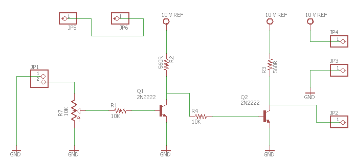
You will want to add some additional electronics to allow you to trigger the VFD FWD pin when there is a PWM signal active. Below is a example circuit to do just this. The op amp used as a comparator in this circuit is a LM324, the transistor is a 2N2222.
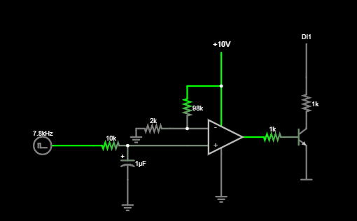
If you do not want to pull the PWM signal from the SO5’s ICSP port, you will need to add some electronics to do signal conditioning on the PWM signal. Below is a example from woodworm. You could also just add a low pass filter before it hits the VFD as well.
I hope this helps.
2 Likes
Like i said i have spent quite a while reading about other peoples experiences and i cant help but be inspired by their accomplishments with their machine set ups.
There is an added sense of accomplishment with this way of doing things as well as the acquired knowledge of the machine workings and the skilled to communicate with it.
Would you mind explaining the use of the ICSP port instead of the provided “spindle” port on the controller?
The SO5 circuitry does not play nice with VFD’s without additional signal conditioning. C3D does the signal conditioning inside of their VFD box. By grabbing the PWM signal from the ICSP port you are getting the signal before it has been messed with by the SO5 circuity, eliminating the need for additional signal conditioning.
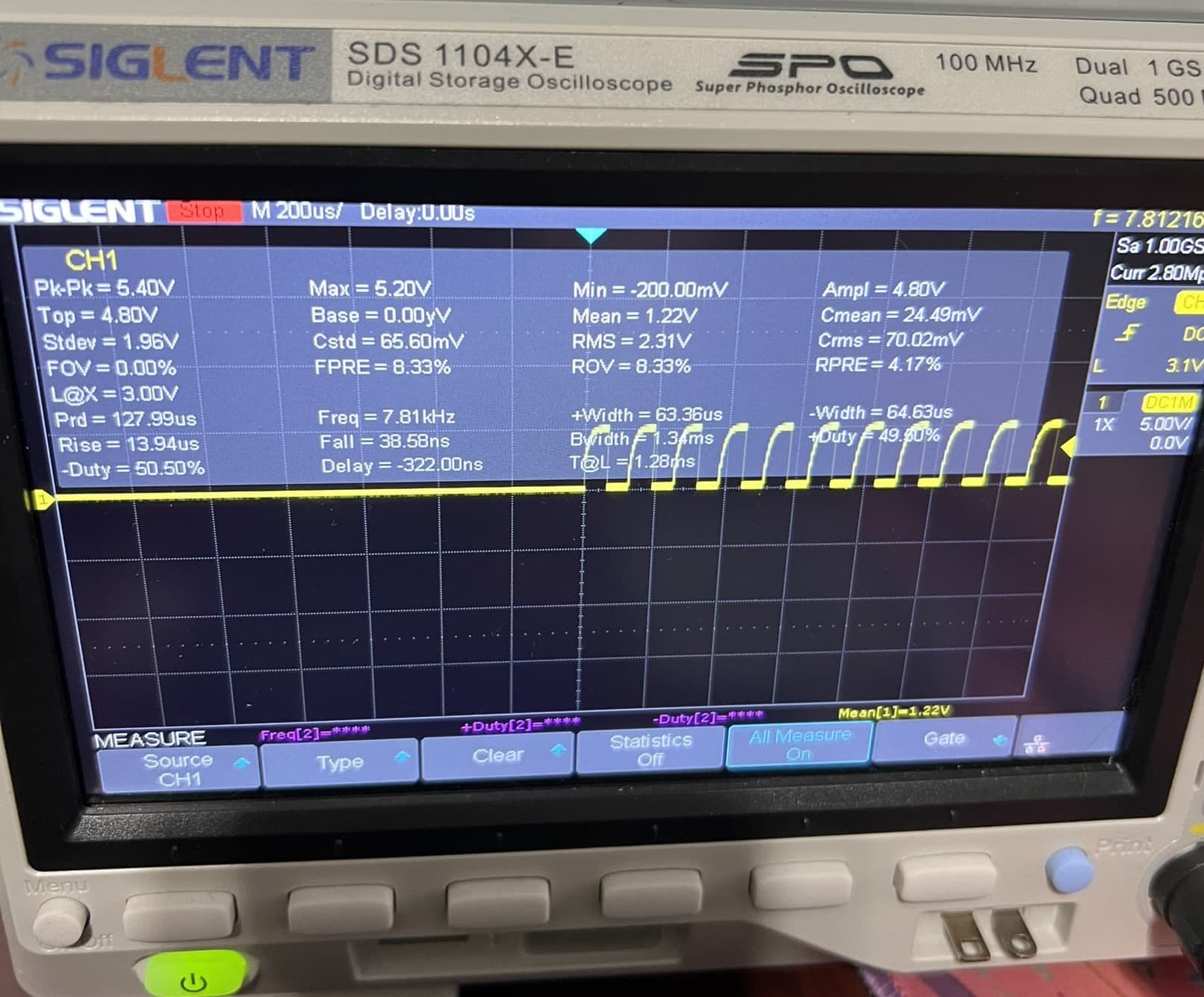
Here is a trace of the PWM signal from the SO5’s spindle port:
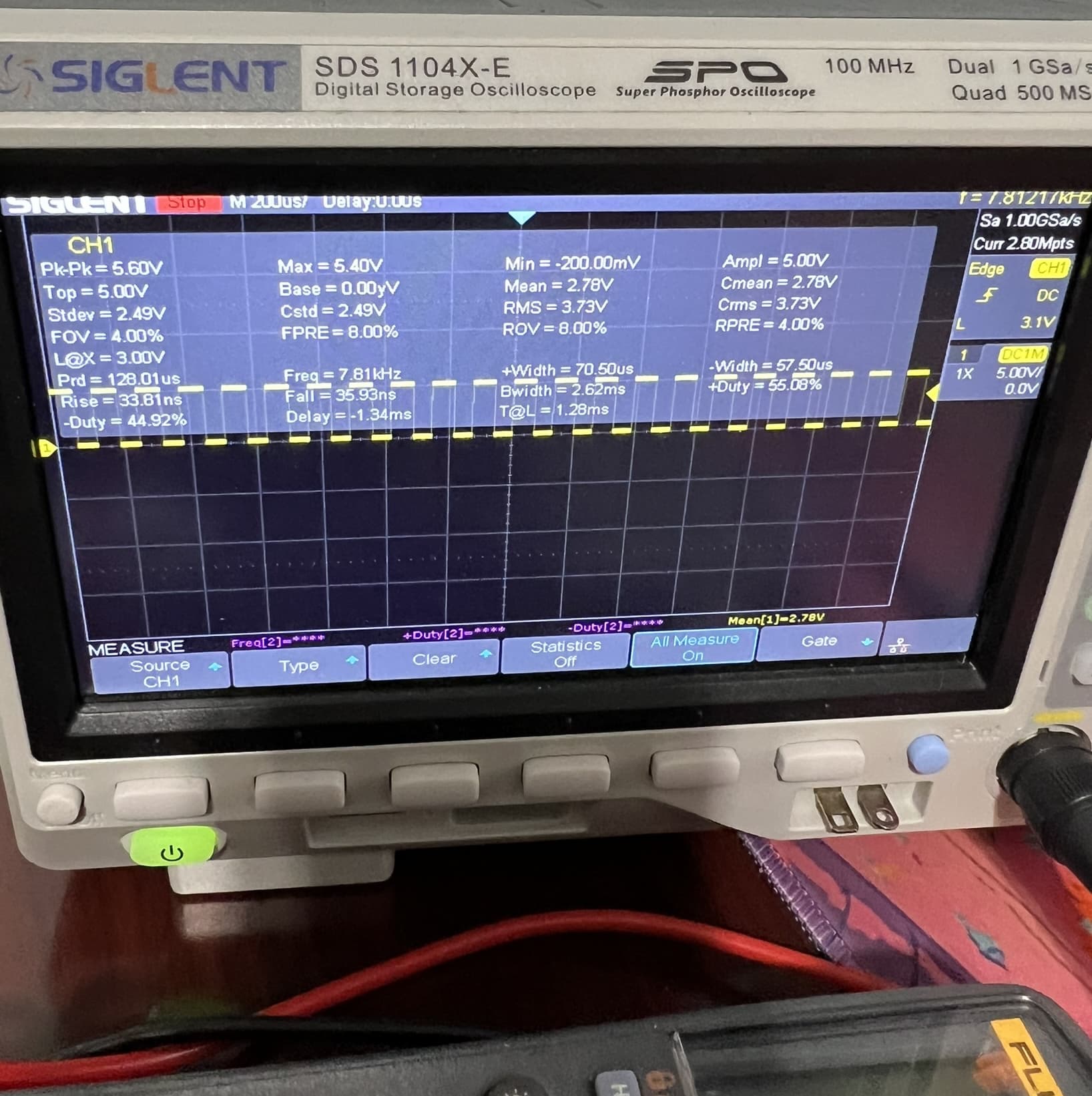
Here is a trace of the PWM signal from the ICSP port on the SO5 PCB:
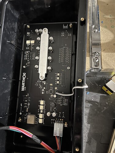
Example of grabbing the PWM signal from the ICSP port(white and grey wire):
3 Likes
Ah i see… well this helps a lot! The ICSP signal will still allow the user to control speed as well as turning the vfd on and off? What type of connector does this require?
Yes, it’s the same signal just grabbed before it gets mangled by R209 and C140 on the SO5 PCB.
I just used dupont connectors in the picture shown above. You can purchase an adapter from dupont to GX12 from PWNCNC that can be mounted to the front panel of the controller which is what I am currently using.
If using the adapter then you can purchase a GX12 cable to go from the SO5 to the VFD. The adapter and cable can also be purchased as a bundle.
You can always source your own connectors and cable as well.
3 Likes
Thanks for all the helpful tips! I really appreciate it!
Which method are you using to power on your water pump and dust collection? Suggested pump and parts?
I have easy access to my chiller and dust collection power buttons, so I just manually start and stop them. If I were to have my dust collection automatically start and stop with the spindle, I would use either the FM1 output to turn on a IOT power strip or the T1 relay output with a added relay and flyback diode.
Water chiller: https://www.amazon.com/Homend-Industrial-Capacity-Thermolysis-Engraving/dp/B07Q5MHJL4/ref=sr_1_5_pp?crid=10WYVTQWITG6N&keywords=water+chiller&qid=1706028850&sprefix=water+chille%2Caps%2C142&sr=8-5&ufe=app_do%3Aamzn1.fos.f5122f16-c3e8-4386-bf32-63e904010ad0
Relay: https://www.amazon.com/Electromagnetic-Socket-Mechanical-Indicator-LY2N-J/dp/B07T12WLMT/ref=sr_1_20?crid=1ER5MOOS1B87X&keywords=relay&qid=1706028877&sprefix=relay%2Caps%2C135&sr=8-20&th=1
Flyback diode: https://www.amazon.com/BOJACK-Rectifier-IN4001-Electronic-Silicon/dp/B07Q3HBM63/ref=sr_1_1_sspa?crid=2DTK7YB50OHLD&keywords=1N4001&qid=1706029166&sprefix=1n4001%2Caps%2C132&sr=8-1-spons&sp_csd=d2lkZ2V0TmFtZT1zcF9hdGY&psc=1
2 Likes
Thanks for the great advice! Seems like this Warthog controller has quite a few capabilities above and beyond what the cnc is utilizing…
Do you have a good suggestion for a relay that will work directly with a single phase 240v, 10amp dust collector?
Does your dust collector actually pull 10A? If it pulls less, then the relay I previously posted would work fine. If it is close to 10A then you will likely want a bigger relay.
Here is a larger 25A relay that would work if using the T1 relay function of the EM60 or EM61 VFD.:
https://www.digikey.com/en/products/detail/omron-electronics-inc-emc-div/G7L-2A-TUB-J-CB-AC200-240/127407
You would need a bigger flyback diode if using the bigger relay above as it energizes at 240V instead of 24VDC:
https://www.mouser.com/ProductDetail/Diotec-Semiconductor/1N5408?qs=OlC7AqGiEDk0pr6B3mpSmg%3D%3D&gad_source=1&gclid=Cj0KCQiAh8OtBhCQARIsAIkWb68dqLRA2jkpphyMs9lRnT2Co4zmVM7H1F2ZOFbLrO7bJ3PhzyrYok0aAn2VEALw_wcB
It is not the warthog controller adding the functionality but rather the VFD. EM60 or EM61 in these examples.
1 Like
Ok so I’ve gotten everything ready to wire the dupont connector onto the icsp port on the warthog board… which of the pins is the signal and which is the ground?
It is a standard 6 pin ICSP port. In the previous picture I posted the white wire is ground and the grey wire is MOSI(PWM signal)
1 Like