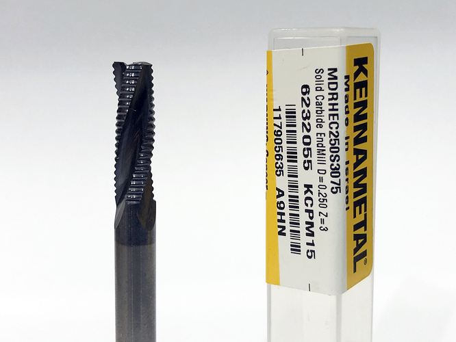
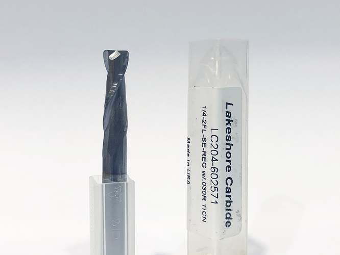
NYC CNC highly recommends them if possible (doesn’t interfere with assembly, etc.) for tool strength/longevity, as the square corner is the weakest point and can chip. I’ve been meaning to get a two flute version to try; I wonder if a single flute is possible in a corner radius 
They are also known as “bullnose” end mills, if you wanted an “aka” in the book.
Datron makes a single flute ball so ide imagine a corner rad SF isn’t impossible.
Lots of my roughers (Lakeshorecarbide TAS and Destiny)have corner chamfers to take a little more abuse.
Hi @allenc,
This is strange. Do you mean @gmack’s Excel worksheet or my simplified version, or both ?
In case it changes anything, I downloaded them and attach them in this post for you to download and try:
FS_worksheet_basics.xls.zip (25.6 KB)
2019-08-11 Speeds and Feeds Workbook.xlsx.zip (155.8 KB)
You can alternatively get the latest version of @gmack’s file in this thread
If this does not work out let me know.
Julien, I wonder if you are going to cover the BitSetter in this version. I think that if you do, you should explain the difference between the BitSetter and the probe because I see this question being asked often on the Facebook group and to discuss the workflow, the need for a proper post processor for the whole thing to work. Some people have also used the multi tool post processor without the BitSetter and wonder why it did not work as expected.
Yes, both. Sorry I was unclear. The zip files you sent opened perfectly on a different computer. (Didn’t think to see if it was a PC/Excel issue.) Thanks for going to the trouble of helping me out.
Be well,
Allen
Absolutely agree. I was working on adding a part about the BitSetter two days ago, I’ll make sure to stress the point about how the probe and the bitsetter are two different things and where they fit in the workflow. Come to think of it, I’ll rework/refine the introductory workflow picture itself to include them explicitly there.
That’s where the latest version is posted as will future updates - hopefully one will be soon. Other relative info is posted there too, like my efforts to get HSMAdvisor’s developer to make his excellent calculator more useful for CNC Router users.
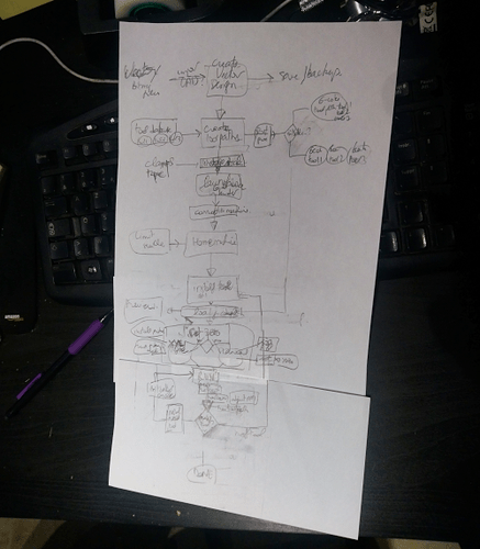
Well, after drawing the full Shapeoko workflow tonight, complete with conditional branches based on whether one uses a probe or not, and a bitsetter or not, I can now see how newbies can possibly get confused ![]()
(pic intentionnally unreadable)
At this point I’m not sure whether presenting this workflow (a.k.a. “the reality”) will just scare new users or help them better understand what’s going on ![]()
I’ll clean this sketch and submit it here for proof-reading/opinions later.
Whenever I see a flowchart like that, I apply the principles from the Drakon flowchart:
https://drakonhub.com/en/how-to-flowchart
Yeah, I should go back to using TCL.
Of course, we can’t read that flow chart but maybe you should split it in two: setting zero and using the BitSetter. In the BitSetter flowchart, you would just say when to set zero without going into detail and refer the reader to the other flowchart.
Setting zero is complicated enough especially for new users with questions like what to do with endmills not identified or profile bits (e.g.: v-bits) when using the probe. In setting zero, you can mention the probe, the paper method and any other methods like the eyeball method.
Just my $0.02
@Julien, can I suggest that you contact people here who produce YT videos and maybe they could use the e-book as the basis to produce videos on some of the chapters/subjects. This would help as some people are more visual or it would nicely complement the book.
Yup, will do. The “big picture” is too big not to be scary and confusing at first glance, so I’ll go with one chart that has the overall high-level steps, and then several lower-level separate ones that deep dive into what each step is actually like in details.
If I wanted to infringe on Luke’s copyrights, I would say “hold my beer”.
Adding on to what Will has added, I think what you need is a GRAF mind map not a flow chart. Flowcharts can be to programmatic at times if you get deep into a subject.
Try these examples at least for context:
how would you show steps/ordering on that type of map ?
Organization is key and these types of diagrams make that much easier than pen and paper.
Any of the added blocks can point to another map that has the numbered detail you seek. You just match the titles/names for links. I’ve not tried to link a GRAF to a flowchart. That would be the best of two worlds.
BTW, this is all free stuff. Start an account, and they don’t bother you.
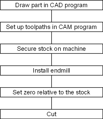
Okay, here’s how a Drakon flowchart might start out:

(EDIT: added install endmill)
One then adds (in smaller, text, and lighter grey boxes) all the checks, and all the things which can possibly be wrong.
Is there a way to share those Drakon charts online, and iteratively work on a shared chart together ?
I’ll sign up and play with it now.
Good question. I was just revising mine — see edit above.
I think just writing things out in outline mode in a decent word processor is the best start — use Heading 1 for all the main stuff, Heading 2 for the branches for the second column, &c.
Does Google’s document editor have an outline mode?
The paper version I was working on right now had a “change tool” after “cut”, conditionnally looping back to either “set zero” or “Cut” depending on whether one installed a tool length offset probe.
Seems like drakonhub diagrams can be shared online easily (obviously) but there is no collaborative editing (that I can find)
A Google Doc would work for collaborative editing, but outline mode may soon become limiting if we want some loops andcondition in there ? what about a Google Diagram : https://docs.google.com/drawings/d/1hkIawgXwm80mMwnVv7XZhwWGjeFgs_XbCvBF4ywOYjc/edit?usp=sharing
If you PM me your google drive names/emails, I could add them to the “can edit” list, and see if that works for collaborative editing ?


