@Vince.Fab You have an IPhone? Numbers will open this file or you can use Google Sheets on-line.
3 Likes
Thanks, I just downloaded and installed Open Office on a Windows 10 computer and opened the Excel file with OpenOffice Calc. Other than the text for the warning about exceeding speeds etc. everything seemed to work fine. I’ll try to find a more compatible font for the warning. Note that the light flesh colored cells are for inputs. The others contain calculations and links that probably shouldn’t be messed with! ![]()
1 Like
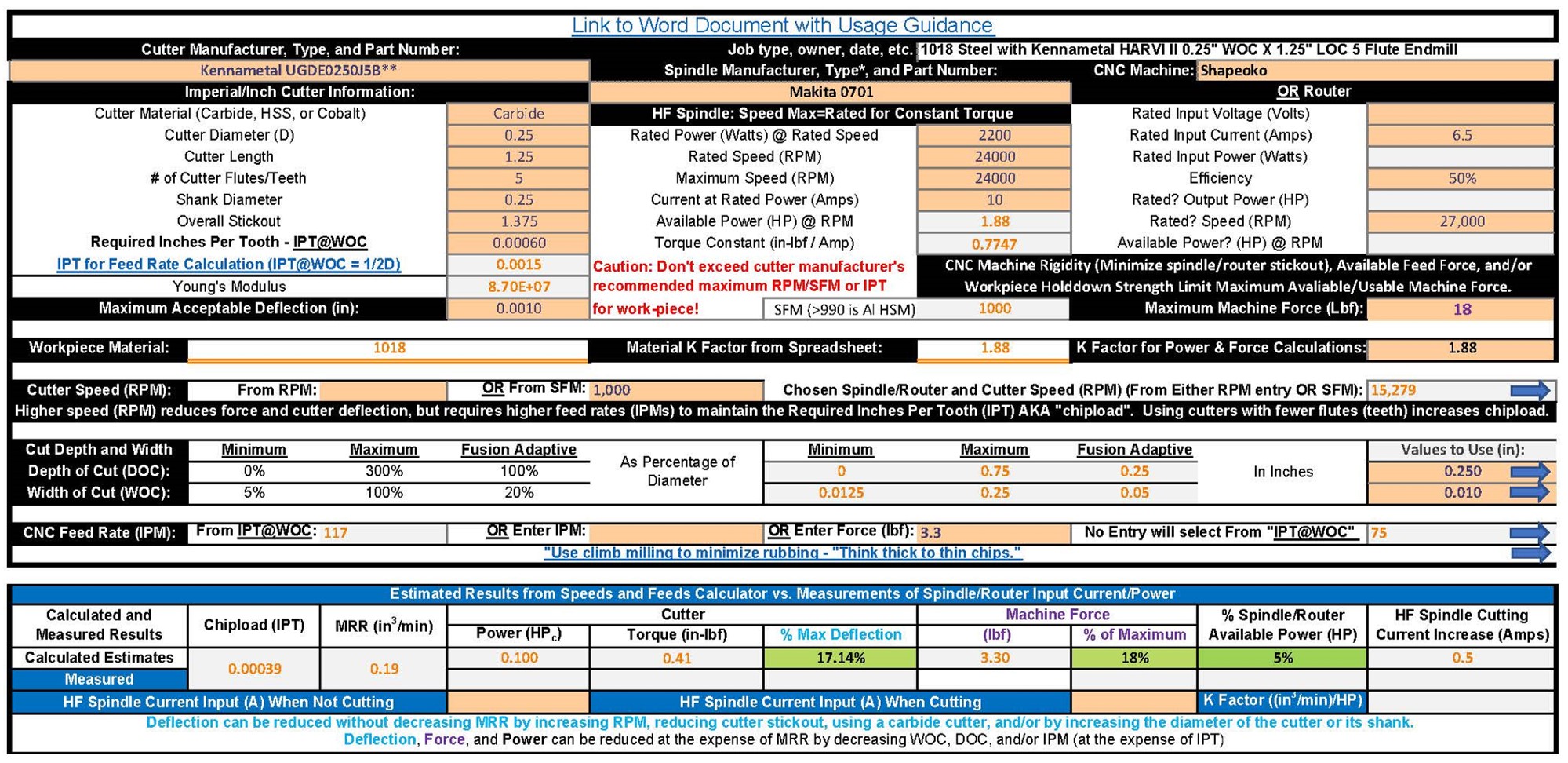
Here’s the latest version of the workbook which makes the warning font compatible with OpenOffice Calc and shows SFM for RPM entries. It also allows entering a machining force value as an option (along with the previous chipload and direct entry options) for feed rate determination. IMO, entering a force value makes the most sense. I didn’t update the usage guidance (yet?), so I hope it’s a logical extension of the old one. Let me know!
2019-08-11 Speeds and Feeds Workbook.zip (155.8 KB)
3 Likes
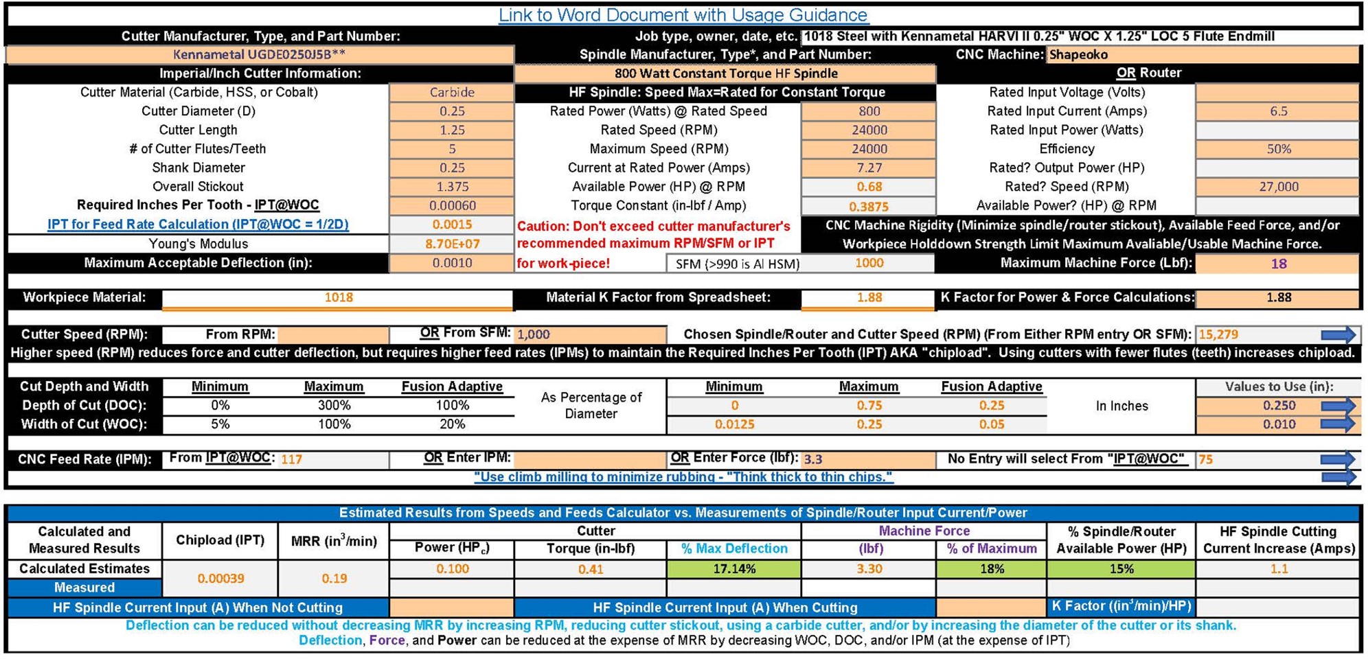
My bad (in the previous post). I forgot to change the spindle description from “Makita 0701” to “Julien’s 2.2 kW spindle”. So here’s another version with this 800 Watt 110 Volt spindle. (Unfortunately that thread is closing in three days!) 
2019-08-11 800W Speeds and Feeds Workbook.zip (155.8 KB)
1 Like
If anyone find a thread being closed interferes with discussion, let us know and we’ll re-open it. I’ve extended that thread.
1 Like
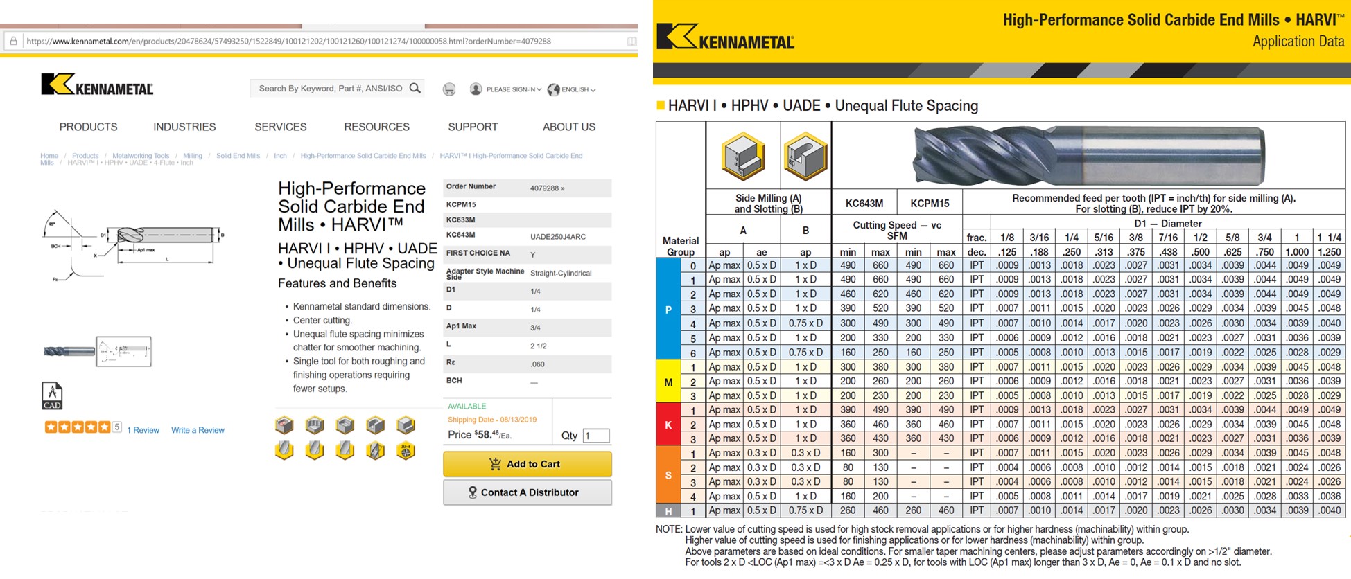
This $55 endmill could give 17 times that MRR, likely last more than 12 times as long (4 flutes / 1 flute X 0.75" DOC / 0.25" DOC, and reduce chatter.
1 Like
Definitely would look into the more exotic endmills if I came into another really big steel project but the sfm of 1/4 at 10k is kind of up there for comfort. Also that machine force is wayyy up there, dunno if that .750 doc would be possible.
The calculator should be really nice for smaller tools and keeping deflection in check.
1 Like
1/2 DOC = 1/2 MRR and 1/2 Force. Your custom machine (with linear slides) could probably handle the ~18 lbf if you feed along the X-axis, since the two Y-axis steppers should support 36 lbf. You could minimize deflection by decreasing the spindle stick-out (raise the work-piece) to reduce forces on the slides. You could also reduce cutting force by reducing the feed rate (and chipload). The workbook enables you to easily evaluate such tradeoffs for whatever material you’re milling.
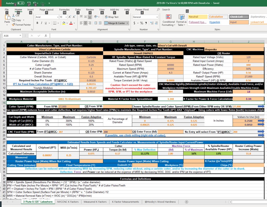
@Vince.Fab posted some really impressive results using his 60,000 RPM spindle with aluminum. I added fields to the attached workbook so he/others could also log temperatures for the endmill. workpiece, and chips if they can and care too. I could also add one for noise level (SPL) but it seems that might be best done in the cutting videos(?). Note that the VFD currents entered may be inaccurate because they suggest a K factor twice what was expected.
2019-09-11 1345 PST edit: I just noticed that I forgot to put the K factor sheets and Hooby’s cool wood hardness sheet into that posted file - sorry! Here’s the corrected version.
2019-09-11a Vince’s 1st 60,000 RPM.zip (155.3 KB)
2 Likes
I might have input the spindle information wrong, does it matter if 110v or 220? Also was way too excited it wasn’t exploding and I thought the draw was 1.3 but I’ll do more cuts today.
Same sfm as running 1/4 at 30,000 so nothing crazy. The noise level was really really low for that type of cutting but again, I’ll record these results better next time.
Off cut topic - is there a chance to calculate a ramping or plunge load with options to change speeds and degree? Plunge milling is on the list of fun things to try 
The workbook doesn’t care what the spindle voltage is. It only needs the spindle’s rated power, current, and speed. But the VFD needs to know the spindle voltage necessary to drive the spindle to achieve those values, as well as what the values are.
“Off cut topic - is there a chance to calculate a ramping or plunge load with options to change speeds and degree? Plunge milling is on the list of fun things to try”
I’ll think about that one.
2 Likes
I’m trying to use your excel sheet to do feed and speeds. When I click on the link to word doc. I get file not found. Not sure where to put the material type. Don’t know what values to use for the Dewalt router.
@Julien looking at the hyperlink address, I think that the word document referenced above was not included in the Zip file.
Sorry, I guess I should really do something about updating that! But, here’s what it was.
Workbook.pdf (57.1 KB)
But, you might find these @Julien instructions from his excellent e-book more helpful until I get around to doing that:
Pages from Shapeoko_A_to_Z_v2.pdf (245.4 KB)
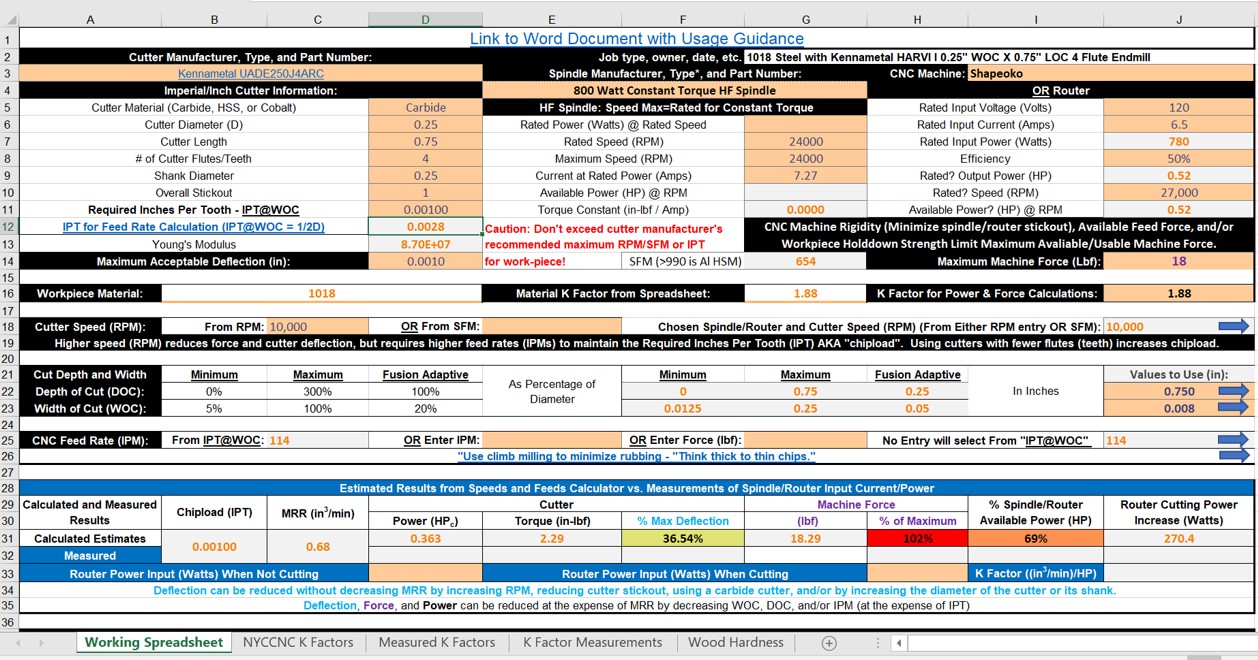
You should also get this latest version of the workbook which is configured for the DeWault router (120V @ 7Amp 16000 - 27000 RPM) that shows what you should be able to do with “stock” Shapeokos with Vince’s DOC and WOC. (Makita 0701 are 120V @ 6.5 Amps 10000 - 30000 RPM).2019-09-11a Vince’s 1st 60,000 RPM with Dewalt.zip (155.1 KB)
1 Like
I downloaded the workbook.pdf thanks. I also downloaded the Dewalt zip file. Curious why the RPM is 60K and some of the other numbers for the Dewalt are blank?
Too late to read the PDF tonight. Will look at it tomorrow.
Thanks again.
@gmack may I ask how the machine force is calculated?
It’s super interesting how the force remains constant when increasing rpm and feed rate but keeping constant ipt.
1/4 at 10k = 0.22cubes
1/4 at 60k = 1.30cubes
Both with a 3.27lbf force
So what’s the negative? How would tool life be shortened if it’s taking the same bite and subjected to the same forces? Cutting at a lower temp as well
1 Like
As shown in the equations at the bottom of the SFPF worksheets, cutting powers and forces are determined by material removal rates, not chip-loads. Excessively high chip-loads waste cutting power and force by generating excessive heat. The cutter, workpiece, and chip all “feel” that heat and are negatively impacted by it.
We should probably move subsequent (and past?) subject area posts to this new thread to keep from de-railing the other posts that have been used. Sorry OPs!
It’s probably best to use the VFD current draw increases for those types of things because they reflect reality, rather than just the estimates/predictions provided by the workbook. Note that the workbook will calculate cutting force increases if you enter measured router input power or VFD spindle currents before/after and during the cut.
This topic was automatically closed 30 days after the last reply. New replies are no longer allowed.