Hi, I am wondering what is the best way to square a vice to the gantry on my Shapeoko HDM. I have looked into using a dial test indicator mounted in the spindle, but it seems like it would rotate and wouldn’t be very accurate. Any other suggestions
Is there anything on the z that you could attach a magnetic dial test stand to ![]()
Its all aluminum parts except for the rails and maybe the spindle, but I wouldn’t attach it to either.
I just noticed on the side on the spindle mount there are 2 M5 threaded holes, so maybe a custom mount could be made for them.
1 Like
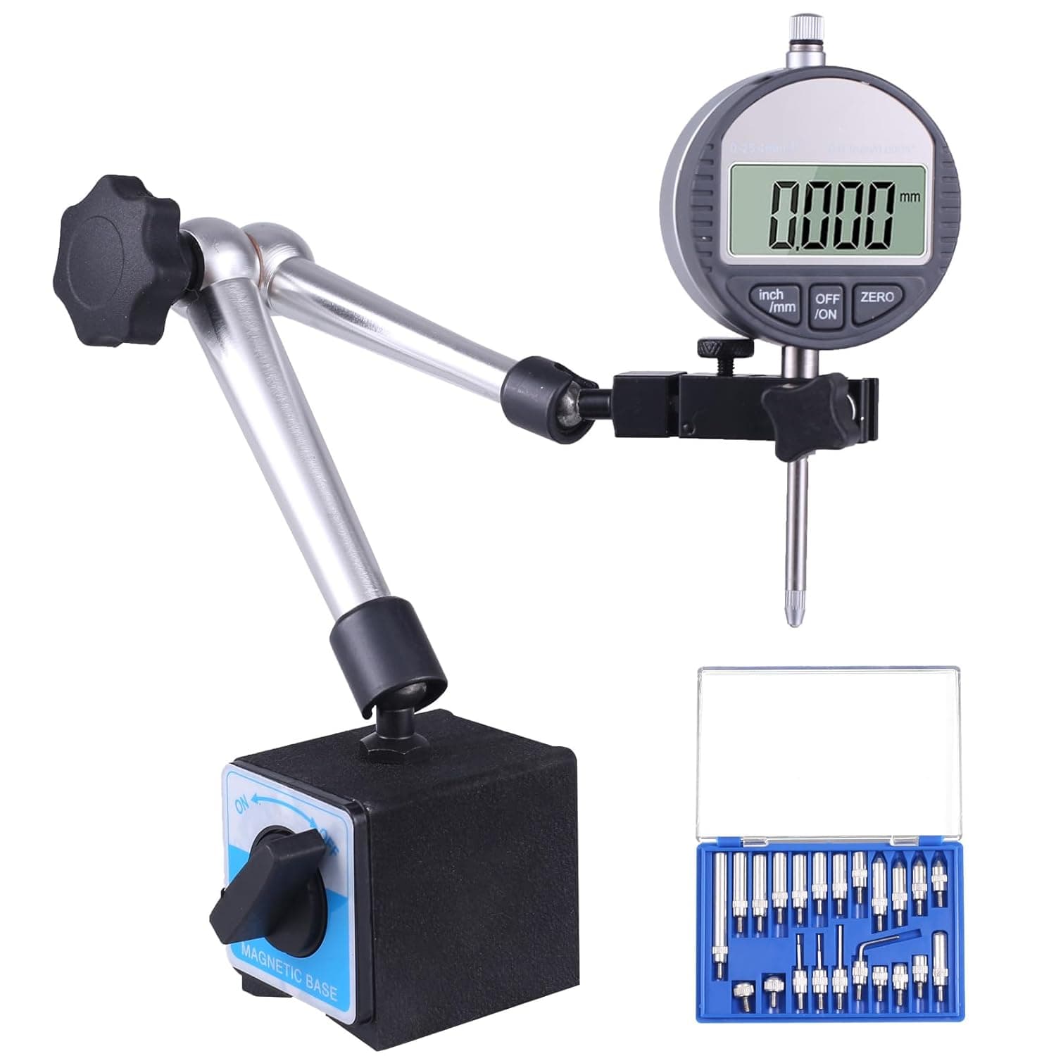
Or, you could buy a mount:
EDIT: If one has a spindle mount which has this accessory mounting feature.
1 Like
Oh ok, where does it mount to on the Shapeoko HDM
One the left side where the knurled nut is. EDIT If one has a mount such as that on the SO5 pro.
Note that the 2 M5 threaded holes are officially for:
(but one may use them for whatever one wishes)
My spindle mount doesn’t have knurled nut. Its the 2.2kw 80mm version, I received it a few weeks ago.
OIC, that’s a question for @Luke
I’ve edited my posts above to adjust for my lack of awareness of the HDM difference.
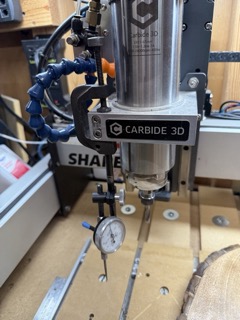
I use the set up pictured below on not only my vice but other work where I need to be square with X and Y. It also comes in handy for seeing how flat of a surface your working with. Basically a dial indicator clamped onto the spindle mount. The tool set is this one, but 40 years newer than the one I have.
1 Like
I use a magnet to hold the spindle shaft still on my HDM
But I can get it within about 0.001 by eye with a dowel/drill blank in the spindle. I go left, right, back to left to verify. If it’s hard to see the dowel touch off, put a light behind it ![]()
1 Like
Have you tried an edge finder?
I don’t believe the VFD spindles will turn slowly enough to make a normal edge finder work.
If someone knows of one which will work at the min. speed of a VFD spindle I would be glad to know of it.
There is at least one which is designed to work w/o spinning:
and for folks w/ an ER-16 or ER-20 unit (and a 3/8" collet) might be a good option.
1 Like
Something like that could work, the mount on the hdm is a bit thicker then yours but I’ll look into that.
I was also looking at a Mitutoyo edge finder on amazon, I couldn’t find a max rpm for it, but I believe the max for most is 1000 - 1500 rpm. On the shapeoko hdm page it says “RPM range of 8k to 24k” So that wouldn’t work.
Another idea I had is to just get a steel plate cut out with matching holes to attach to the spindle mount side, and maybe countersink the holes so the bolts sit flush.
The dovetail mount is only on the S5P.
1 Like
I had no idea carbide neutered the spindles so much that they have a min rpm of 8k.
As someone who has done quite a bit of research into spindles over the last 4 years I can tell you that it isn’t just Carbide3D. Generally 65mm spindles have a lower RPM range of between 5k and 10k RPM. Most edge finders require less than 1500RPM to work. Higher than that and the end can come flying off (ask me how I know). I was able to get my highly modified BLDC Dewalt trim router to spin that low, but it was very unstable and had almost no torque. Most edge finders are designed for Mill Spindles that have a top end speed of 8k RPM but are happier around 400 RPM.
6 Likes
They need to run that high of rpm’s to stay in the torque range.
But there are lots drilling and indicating operations that can be done at much lower rpm’s.
I run 80mm spindles at can run them under 100 rpm. I regularly drill at 3k rpm, and I use an edge finder at 800 rpm when I need to use them.
It makes sense why it’s so difficult to run an a/m spindle on a my 5pros as they never shut off and run at a couple hundred rpm’s when commanded off.
1 Like
We struggled with this concept; getting the stock - or jig to hold the part to machine to be square to the gantry. In the end we clamped down a piece of aluminium bar along the left side, and machined a ledge level with the bed along that with a stop at the front. we leave this clamped down with screws through it into T-nuts. Then I placed a square bit of ply into that ledge and stop, clamped it down and machined a square out of it leaving an ‘L’ shape. Now all we need to do is place the ‘L’ into the corner locator of the aluminium bar, locate the stock or jig ( or vice for you) into that ‘L’, clamp it down, remove the ‘L’, add more clamps if needed and voila, its square to the gantry - and in the left front corner is in the same place each time.
We have thought about adding some aluminium bar along the front edge - screwing them down to the bed between the T slots and machining along there to ensure each is in line and parallel to the gantry to make it easier to keep larger stock square to the gantry.