That’s some pretty quick & solid investigative work.
That would hopefully be far enough to show up if the Y belts were variable along their length yep.
That’s not a big enough error over the full frame size to give us the error you’re seeing over 50mm.
Now this is looking like a possible culprit.
I covered some of this in the video on belt tension which might be helpful
It seems your X axis is resting slighly off square with the Y axes. As a first test I’d suggest the trick of, with the machine powered off, gently rolling the X beam backwards until both of the Y plates stop in contact with the rear frame. Then power the machine up and let it home normally.
This ensures that the X beam is square to the frame and as you’ve already checked the frame is pretty close to square, it also means the X beam should be square to the Y beams.
Once you’ve let it home, check the gaps between the Y plates and rear frame again to see if they’re still even. If that’s still good, jog all the way forward and measure the gaps at the front. These should also be close to even, if they’re not close enough, you can balance the Y belt tensions until they are.
If starting up like that fixes the issue then you can shim one or both ends of your X beam where it bolts to the Y plate to help the machine come to rest in a square position.
Whenever I have what I think is an accuraccy issue I run a roughing pass with 0.5mm material left (bit more on wood, bit less on metals) and then come back with a couple of finishing passes to make sure it’s not cutting load deflection messing me about.
I’ll see your simple solution and raise you loosening all 8 X gantry screws along with all 16 Y Rail Screws (not to mention having to use a screw extractor on 6 of them) then retightening everything while pulling the X gantry snug to the rails. I was able to do this and keep it snug so maybe there was some tension/torque in the rails (I move my machine around more than most).
Cutting a DCS test now to see if I’ve improved. If not I’ll try your method.
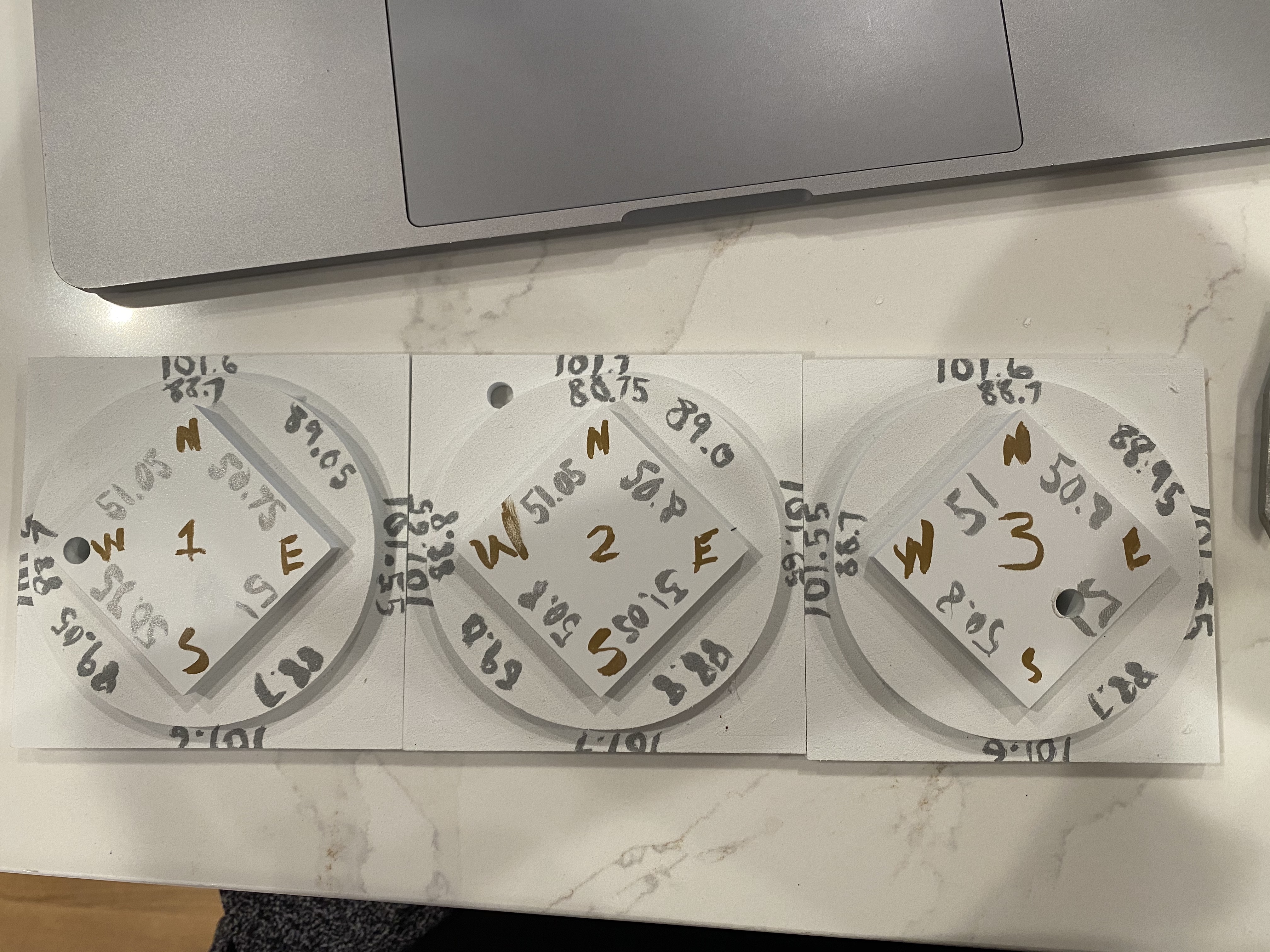
How “even” we looking at here I’m getting .7 - 1mm difference between the two gaps? The gaps align in a X pattern… Aka after honing SE = NW and SW = NE gap
Is that with the X beam pushed to the back for power up or just from the resting position?
It sounds like your Y travel is balanced which is good.
How far out is your DCS test piece now? Good enough yet?
I have found on mine that the startup angle of the X beam isn’t particularly consistent so if I’m doing a job where square matters I jog to the front and check.
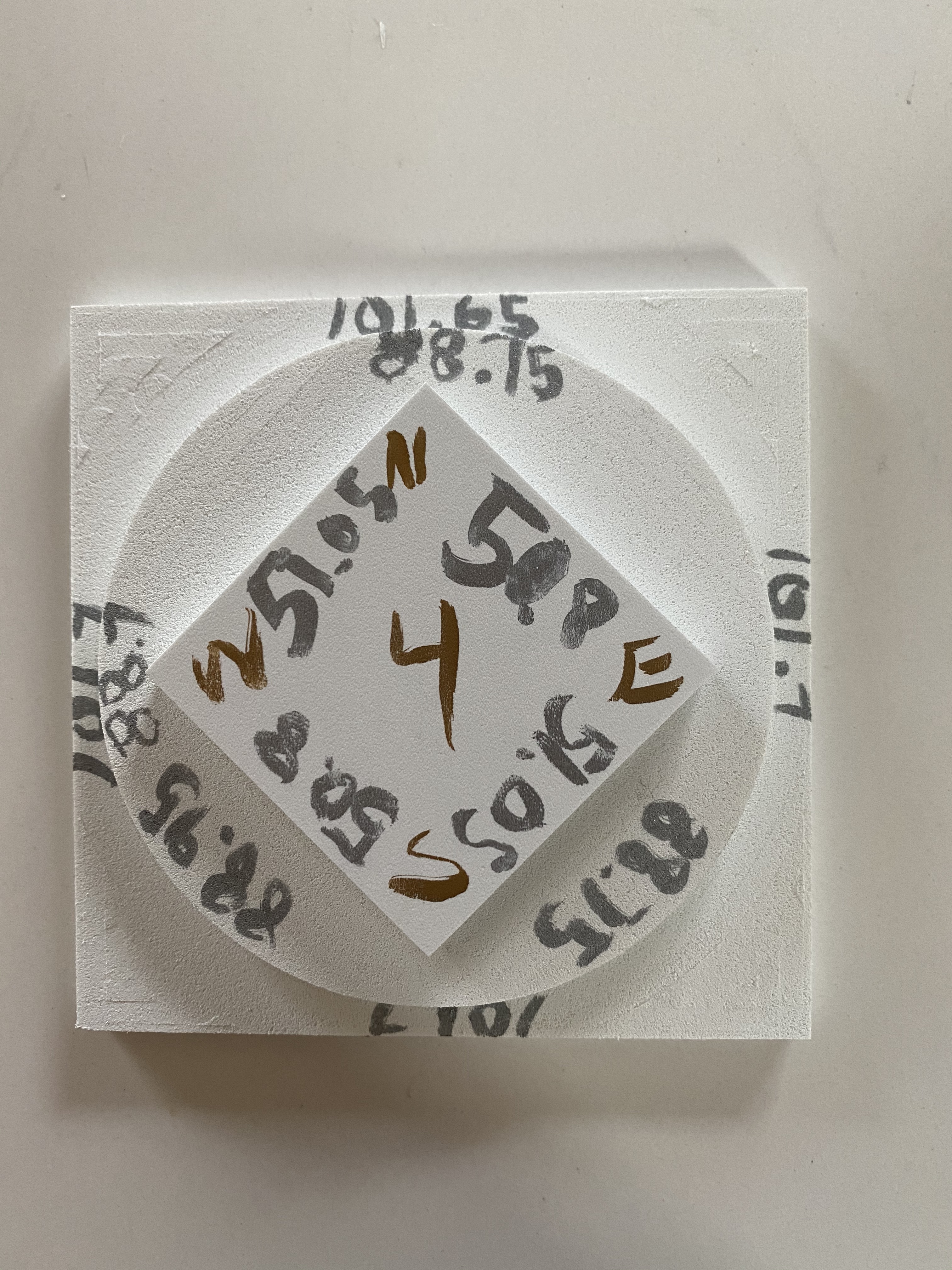
Push to back turn on. Measure full jogged back gap and fully jogged forward gap and overall the gap averages somewhere around 5.75mm some gaps being as low as 5.25 and as high as 6.25 depending where I stick the calipers in.
We’ve improved… debating going back stock $101=40setting. just to see what it does. on one more diamond.
Well, it’s getting better and it looks like you know what to tweak now.
I might try shimming the ends of the X beam to help it run square to the Y rails now.
The cheap feeler gauges idea is an excellent cheap way to get shim stock.
edit - It’s also worth remembering that you will never, ever get any machine perfect and knowing when it’s good enough and getting on with using it can be the smart choice
@LiamN given all the issues with squaring wouldn’t it make the most sense for C3D to put a inductive switch on the X- side as well and let the honing cycle work whats square each time?
Or is the feeling that the machine slightly changing square each time would be more annoying then just being “machine square” to any features on the waste board etc…
The two Y stepper motors are driven by the same step signal on the controller so they have to step together. On larger (or upgraded) machines there are frequently two Y homing switches and the controller individually homes the two Y axes to get into alignment at startup.
One day, when I replace my controller and all the motors…
A little too tight on those belts?
They look like the steel core belts, Thought you did the maintenance kit with Fiberglass belts.
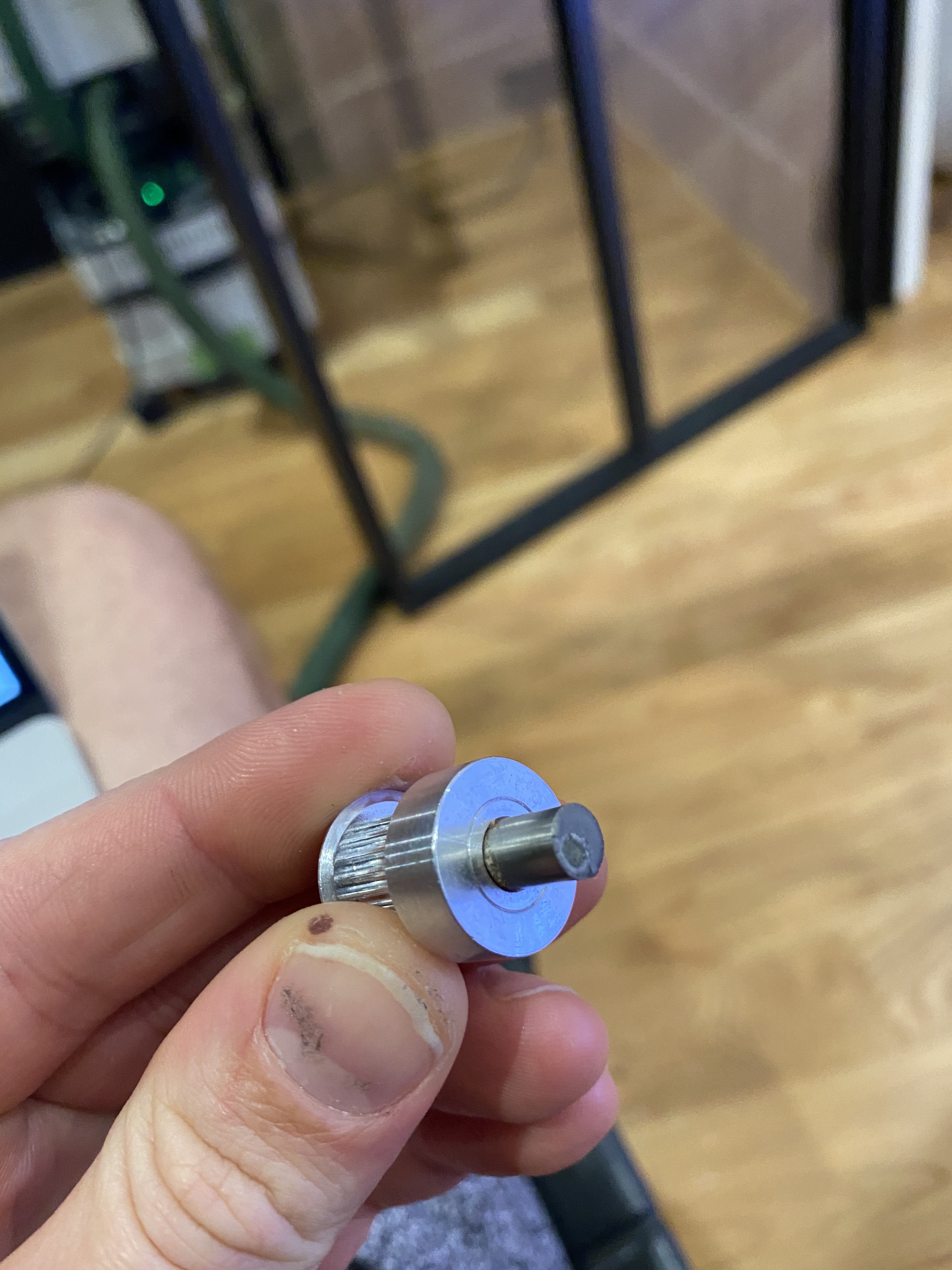
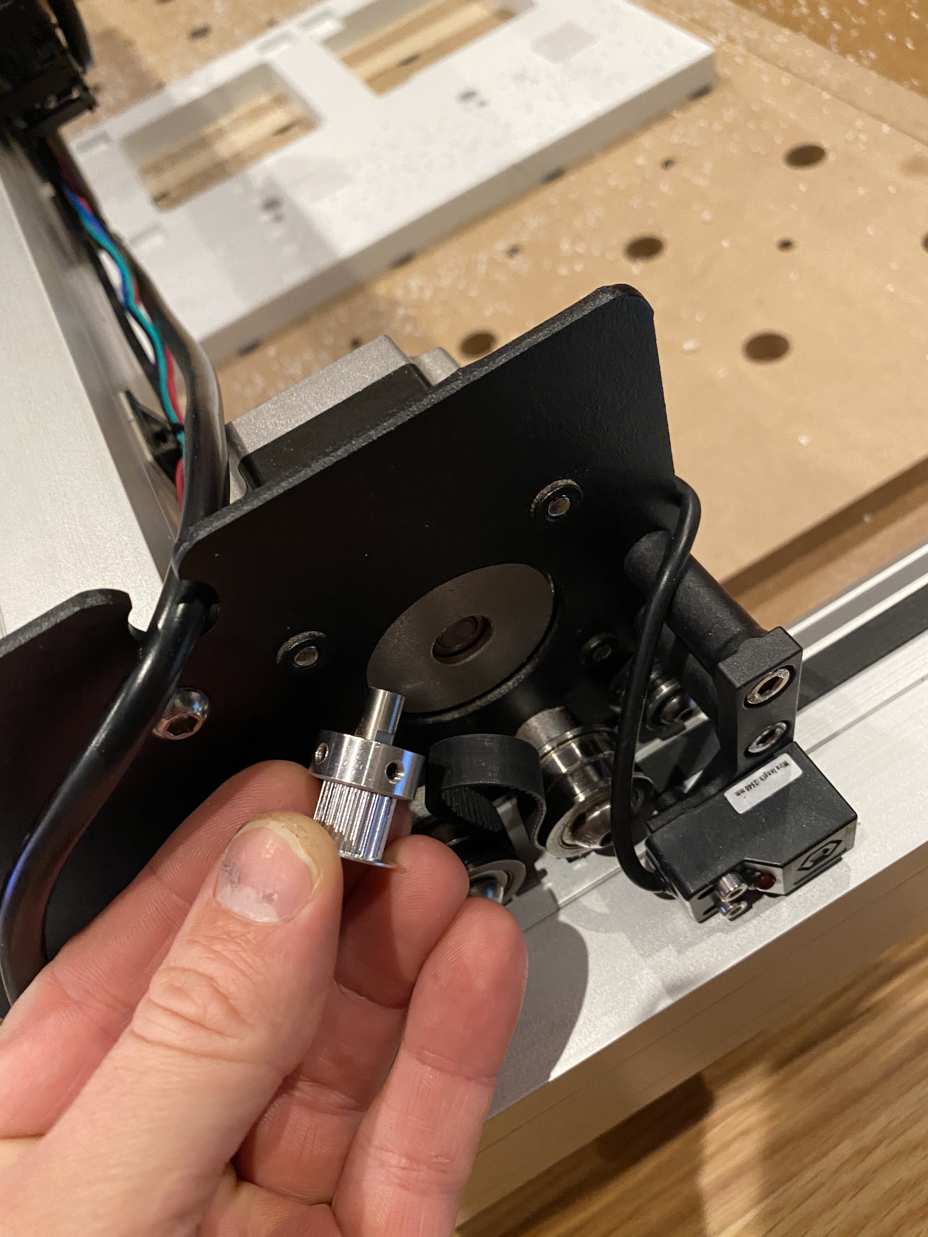
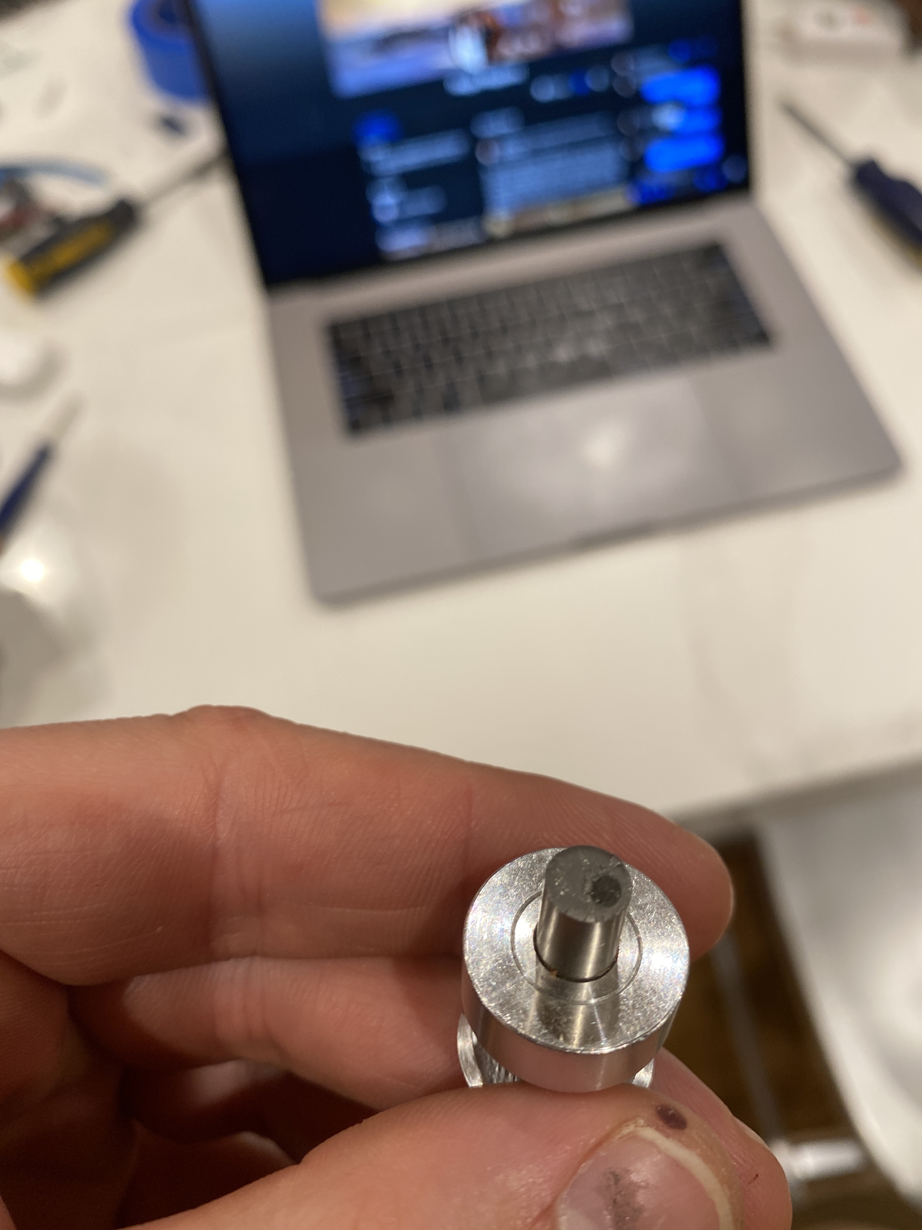
How far did the pulley have the belt over the end of the shaft? My pulleys have the belts running around 1/4 inch beyond the stepper shaft… not a good scenario.
One of my projects will be to build a bearing block to mount the pulleys in, instead of it being mounted the way they are now, riding out beyond the actual shaft = shearing force, which from the looks of your pic above, that shaft was sheared off by too much leverage. I would think those steppers are designed for radial force only and not actually for leverage.
Something you might try. When you go to set the belt tension, set it to where when you try and move the associated assembly, only tighten enough that you can not easily develop slack in the belt by manually moving that associated part, then when you test for accuracy, adjust the steps required to achieve the result you want. Making guitar sounds is irrelevant, it is not a guitar. The y-movement will require a little more effort as there are two belts.
Like Liam mentions above, you will not ever get these machines perfect, but you can get them close enough.
I did not @ Liam as I do not want to get him dragged into my procedural practices (pretty sure his practices are more precise)
You know I thought about this… but I just set the $101 value below the stock value of 40 to get it = to the expected measurement. So In my mind the belt was looser and ergo providing less resistance then the stock setting would expect? Or am I thinking about that incorrectly?
I’ll take a closer look at the belts tomorrow morning. But they all look very different then my original steal core.
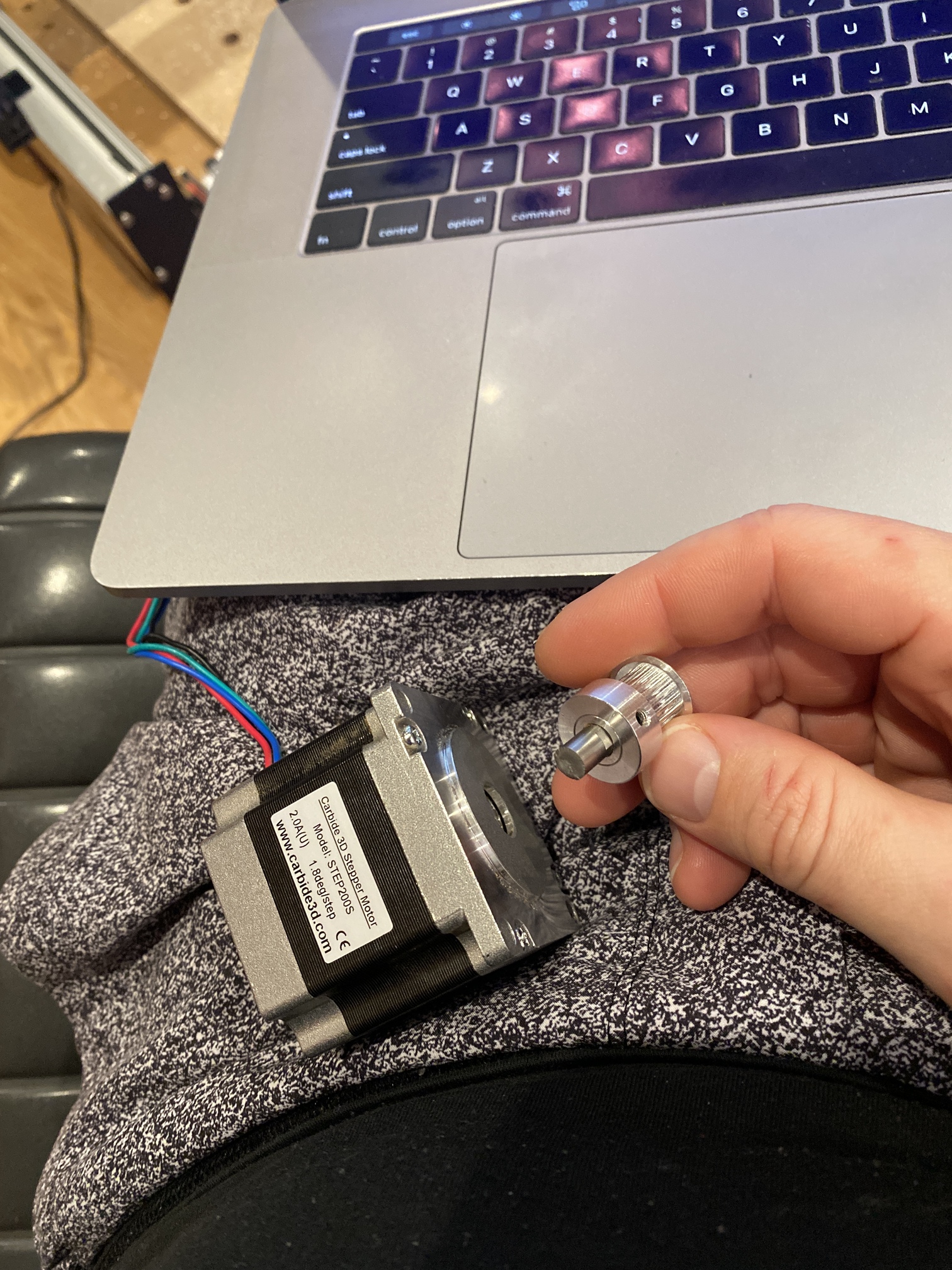
Not sure I follow you on the pulley, I never replaced the pulleys so if it didn’t move when it came off (it’s pretty well seated on there) it woulda been mounted there since I got the machine 1.3 years ago.
Does the black / dark spot in the middle of the shaft offer any clues to the metallurgists?
That dark spot was the last bit to go.
The shear started at the side further away from that spot. That dark spot was broken different because when the shafty started to shear, that dark spot was broken in a different direction.
so, it cracked (from too much leverage force), then all that was left holding was the dark spot and it was snapped.
BTW, I am not one of those metal lurkerests… Just have repaired a LOT of broken machinery and know how to diagnose/ prevent stuff like that.
I do not see the “Burr” that would indicate a twist, so it looks (to me) like a shear.
If I made that machine (LOLOLOLOL) the pulley would be in a solid casement with a bearing at each end, then coupled to the stepper shaft… but that’s just me.
Let us know at support@carbide3d.com and we’ll get that out to you as quickly as we can.
Send in a new e-mail to my attention and detail all the specifics and we’ll try to work out everything needed to ensure that you get back up and running and cutting to a reasonable tolerance.
Most of these stepper motors are only rated for a small radial load of about 100N on the shaft. Other than the obvious bearing wearout the other failure mode the manufacturers warn of is a work hardening type process of repeated stress failure in the stepper shaft as it is constantly flexed as it rotates. It looks like you might have been a victim of that failure mode.
I’ve been considering 8mm shaft motors for my Y axes but haven’t yet found one which the Carbide electronics will be well matched to.
If you’re pushing up to the point where the stepper jumps a couple of steps then you’re finding the required minimum tension for the belts to operate ‘normally’ with both the extending and contracting sides contributing to the restoring force as the drive system needs tension on both sides of the motor
edit - that’s matching the belts to the motor sped, of course if your cutting and dynamic forces never get to breakaway torque then you can use less
I’m back up and running. I’m happy with this until i upgrade my table (the floor) and/or upgrade my base to all aluminium where I’ll spend the time trying to get rid of any sag in addtion to out-of-square.
Final $100 and $101 settings on this are:
$100=40.0106887
$101=40
Largest gap from expected measurements is .01" or .25mm and overall relative deviation from one side of the DSC to another is .05-.15mm on each shape.