which I described above and is what I am currently modeling?
I’m thinking as a first approximation rather than halving the thickness I divide it into thirds and round the bottom of the channel (hey! I have a BitSetter, I should use it, right?):
I’m questioning your assumption to use the “midline” of the bending material.
In specifying parts to many jobbers, in my previous life making boxes and chassis components out of aluminum sheet, I always based my drawings on the following:
The material will bend around the point of contact. Any material beyond that, the thickness, will stretch and shrink to fit the final radius.
Of course, that changes some depending on the thickness, but mostly with thicker material.
My understanding is that this is actually really complicated to pull off without trial and error. I know that F360 has some tools specifically for this (and requires specifying materials, acceptable radius, and so forth), but otherwise I think this probably requires some experiments to see what’s acceptable and what isn’t.
I typically use a “K factor” to calculate my developed length. This factor is dependent on material type, bending style, and radius of bend. Here is a good article describing this K-factor.
For example: For mild steel, I start with a K-factor of 0.375, up to a 0.5" inside radius using an air bending style. For a bottom bending style, the K-factor goes to about 0.4 to 0.45, and for coining, a 0.5 K-factor usually gives good results.
Unless you are trying to hold +/-0.005" for your bend lengths, I would just use a 0.5 K factor.
You need to have a general idea of your radius, and I’m assuming you will be bending these by hand?
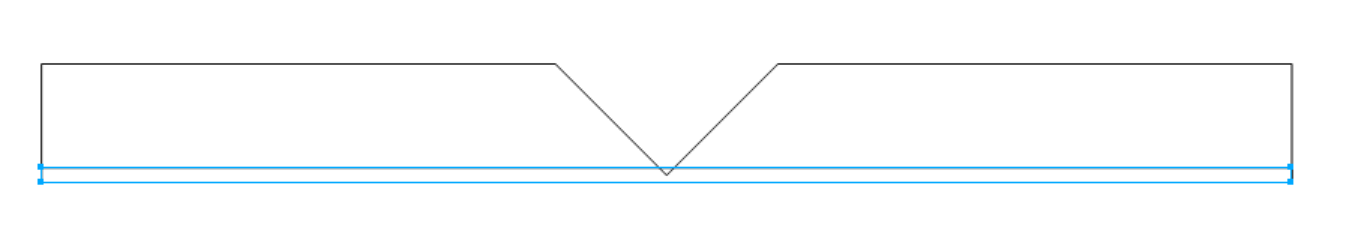
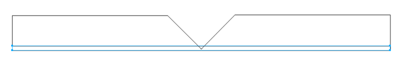
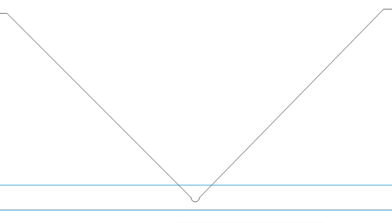
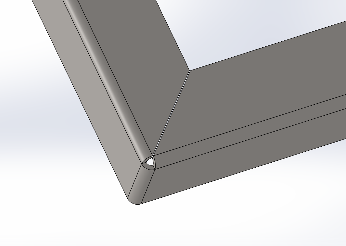
As far your V cut, what you have looks great. The little radius you have at the bottom of your V is a bend relief, this needs to be about 1/2" of your material thickness for the diameter.
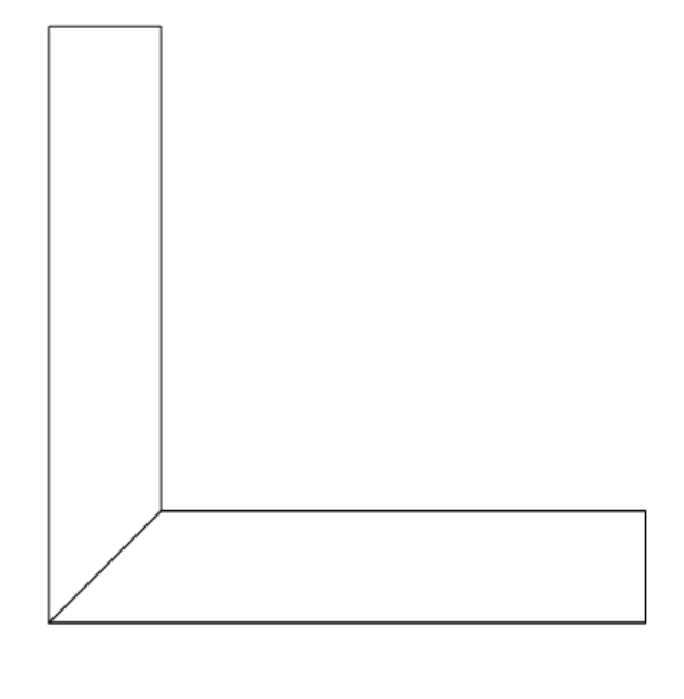
Here is a quick Solidworks model showing the relief in the corner:
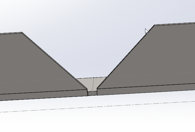
and what that looks like in the flat:
This is just to give you an idea. For cosmetic parts, I would use the radius in the V like you have.
I hope this isn’t just gibberish, and actually helps.
Glad I could help some.
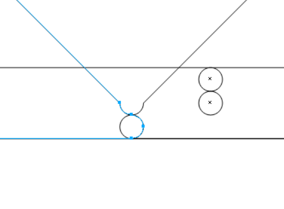
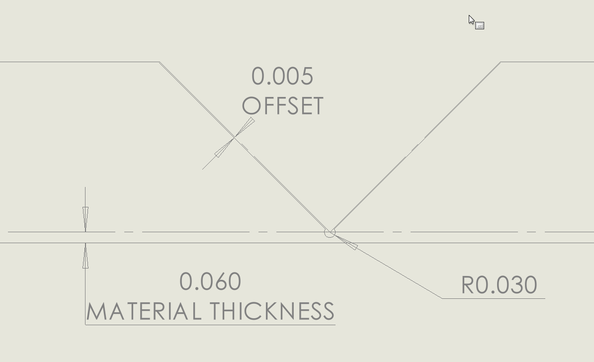
I would make your 90° cut .005 offset to allow for some interference when you make the bend. Here is a quick sketch assuming material is 0.060" THK.