For some reason I started thinking a fourth axis would be nice for my SPXXL.
I remember this being asked about in the community and there was no connection for a 4th axis on the control board. My mind wonders sometimes.
That being fact, what if you take the X or Y axis and connect it to a 4th axis motor…
Could this be programed to operate as a 4th axis but with only 3 in use for this operation?
If this concept is feasible, you could just setup a switch in the control box to change one axis to the imitation 4th axis.
this is how many of the diode laser 4th axis addons work, you end up trading your Y travel for rotation. I’m not sure whats involved software wise though and I think you’d have to lock your Y axis somehow so it doesnt move (not having power anymore)
This has been done as long as Grbl has been around. Still 3 axes. You just have to adjust your steps/mm to the rotary axis. You never want to switch steppers while powered.
Here is my thinking on this. Rather than promoting a third-party product why not have a C3D solution. I’d be more inclined to using CC-PRO if this feature were a part of it.
Besides, I am a cheap old man and do not wish to spend $219 for a new control board. Does CC / CM even run the Black Box? My guess is NO.
As far as a 4-sided flip jig goes. (Will) This looks and sounds very complicated. I do not work with aluminum. I have no idea as to any software to create the Gcode needed.
I am thinking along the lines of simple vector art or lettering and engraving onto cylindrical objects.
So, I had a brain fart which sounded simple to me is more complicated and harder than I imagined.
Folks have done a rack and pinion system where Y-axis movement is converted into rotation and the X-axis moves along the centerline — the Scorchworks guy has a utility to support that sort of thing.
Did you see my post on that thread. The black box is not going to get you any closer to a 4th axis. Whether you use a 3rd party board or the Carbide 3D controller, you just need to fix the axis you’re not using and plug the rotary axis into that driver on the controller. You’re not adding a 4th axis, you’re trading X or Y for rotation.
For a true 4th axis, you need to swap for a controller that can handle it.
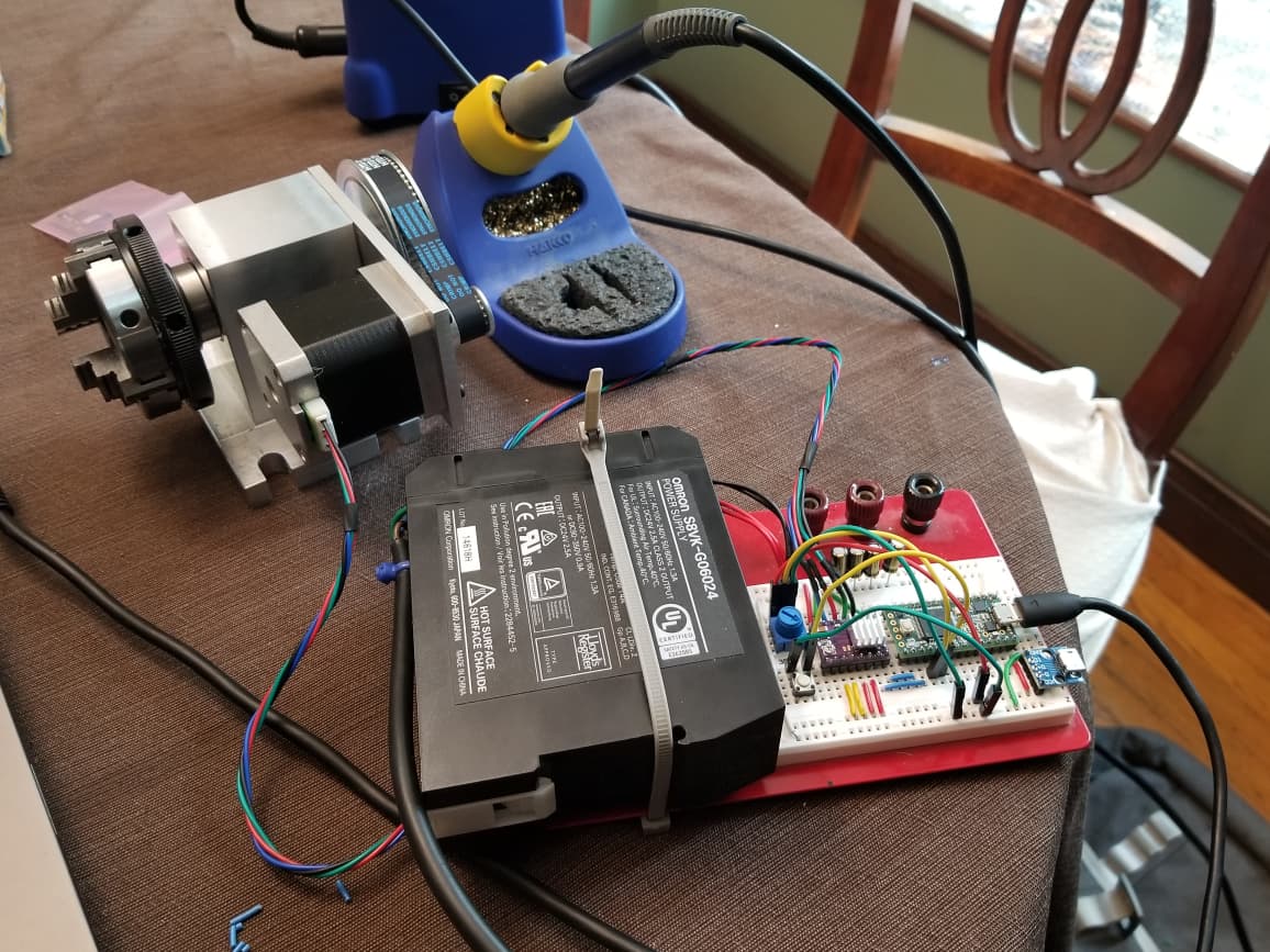
I’m toying with this. I just took the plunge and got a cheap rotary axis on Amazon and connected it to an 8825 stepper driver and Teensy 3.2. I have a button and potentiometer in the circuit so I can use two “modes”:
continuous: potentiometer controls the speed by setting the delay in microseconds between sending pulse commands
flip: rotating the potentiometer between extremes flip-flops the part back and forth 180 deg
For now I’m completely “faking” everything in CAM. I use normal operations, but I have a sketch that’s the length of my part, but only maybe 0.5mm in width from the centerline. I constrain e.g. a pocket operation to this machining boundary, which has the tool going back and forth. Meanwhile I’m manually adjusting the speed using my potentiometer.
I haven’t used the flipping routine as there’s a bit of play when the motor is fixed and I try to rotate it. I’m pretty sure it’s coming from the belt… and I’m not sure there’s a good way to completely eliminate this.
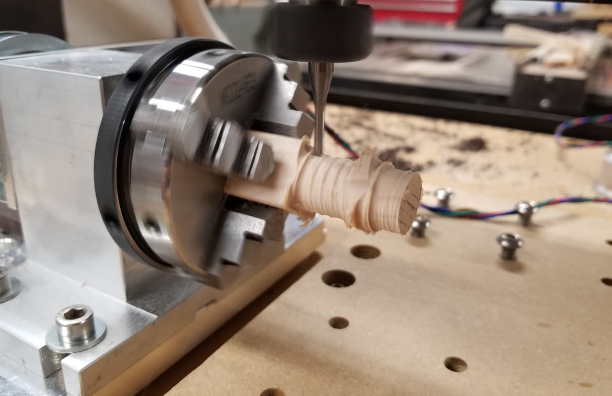
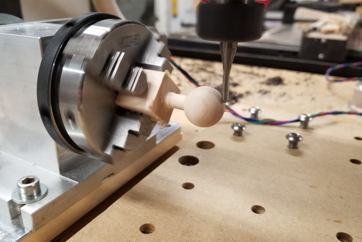
Anyway, preliminary experiments with my manual setup have worked… pretty amazingly in my opinion. Roughing sucks, but once you get to the final pass, the parts are waaaayyyy better with respect to axial symmetry and surface finish than my normal two sided flipping approach.
That said, I’d love to try this motor swap hack so I don’t have to manually control speed. I’ve heard of swapping, but now how people specifically lock the y axis in place. Or maybe I could almost reverse my approach:
use my teensy/8825/power supply to hold Y motors in place after manually moving to the desired y=0 in line with the rotary axis
plug the a-axis board into the Shapeoko
Anyway, just documenting my efforts and would be happy to brainstorm/update anyone here or via PM as I continue to make progress. Currently I’m machining a new plate so I can use my original SO3 Nema23 to replace the Nema17 it came with. Should have that done tonight and ready for more experiments!
Edit: some pics.
Building my circuit and prototyping the motor control (this was my first time using a stepper motor, though I have a lot of arduino experience in general):
This is why I’d like to go integrated. A balance between rotational speed and % override via Carbide Motion wasn’t optimal. Led to icky roughing results sometimes: