Griff
(Well crap, my hypometric precursor device is blown…)
1
Received my Carbide 3D touchprobe yesterday, just finished installing it.
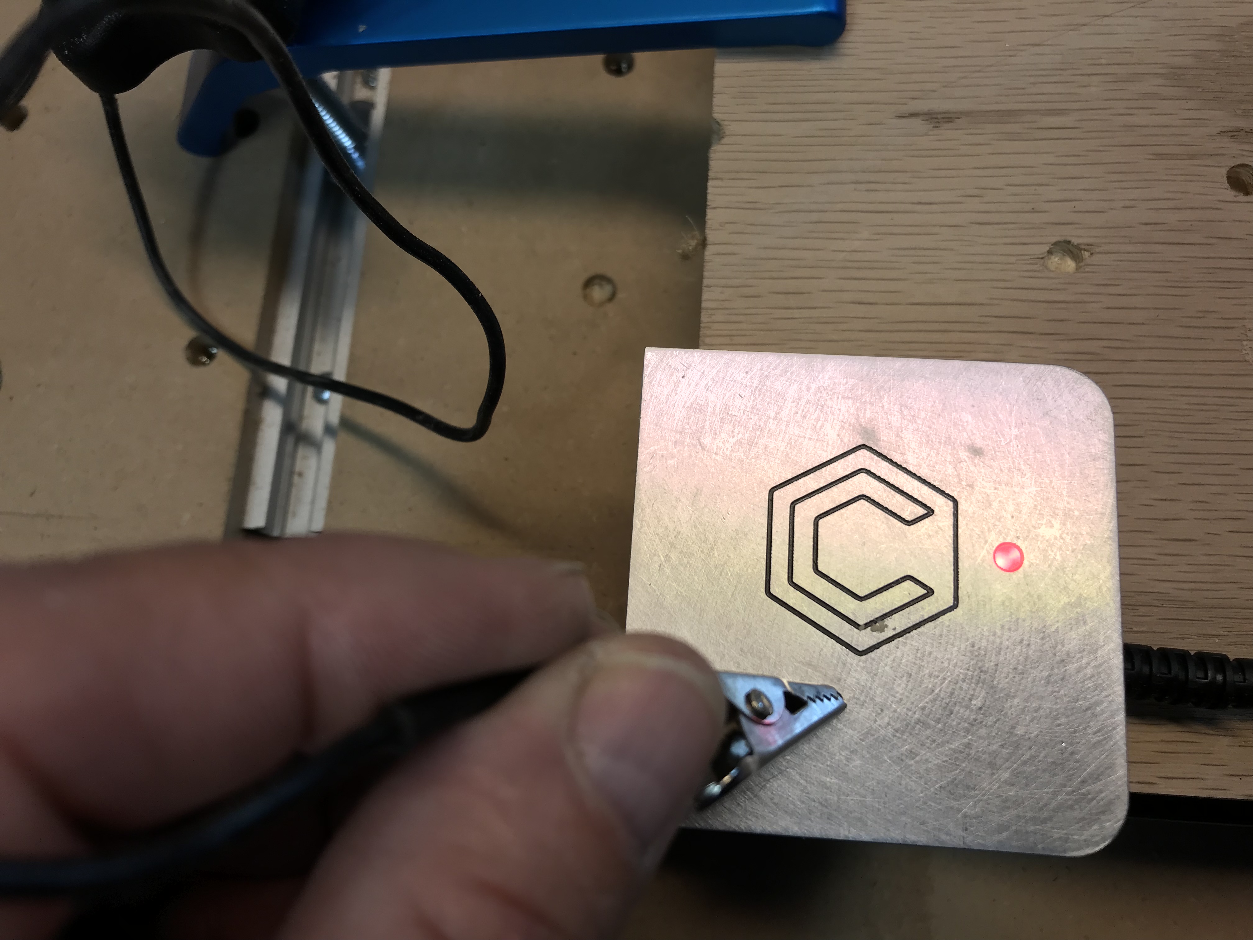
Running CM 4.0.409, version 2.3 controller. Tested probe to check ground, LED changed to red. Located my 1/4” Ballnose over the probe target as per the instructions, connected clip to cutter, touched probe to cutter to re-verify, got a red led. Initiated the probe cycle in CM, cutter slowly descended, touched probe target, led turned red, cutter continued to descend causing an error. I’ve made 3 attempts, same problem. Error 3 and error 4. If that means anything.
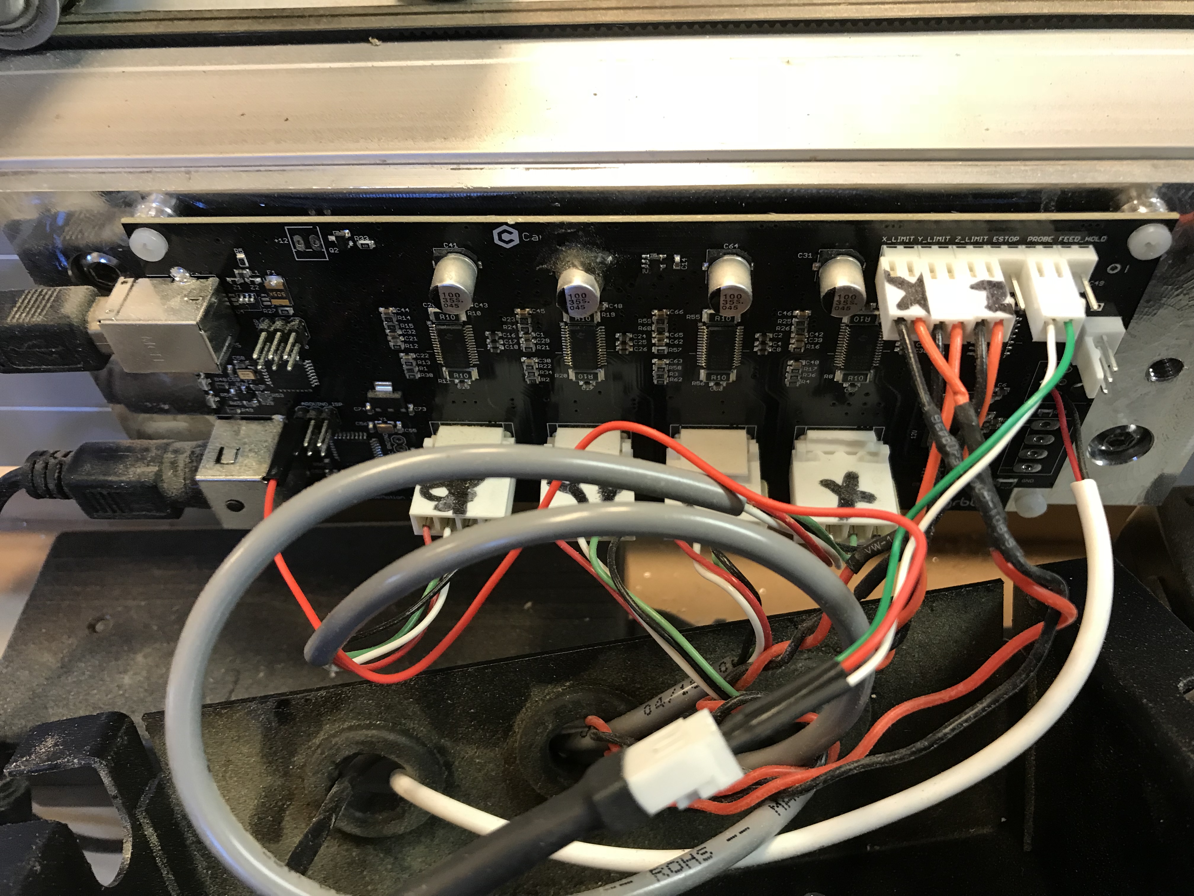
I’ve now triple checked the wiring, all appears correct. Do I need to “enable” probing?
Would it matter? I would think that end mill manufacturer shouldn’t matter provided that the mill conducts electricity and you select the correct size / type. My probe should arrive tomorrow, but I noticed the same thing playing with CM 4 and probing: It seems to only have presets for the Carbide end mills. I would think that any 1/4" Flat should work the same as a Carbide #201 or any 1/4" Ball should be the same as a #202. I hope we have the ability to enter custom values for type of end mill in the probe section.
Yep you do, it’s a setting in CM as part of the probing cycle.
@Griff - there is no need to use ‘official’ cutters, any tool should work as long as they match the spec i.e. diameter of the preset - but even then the Z should work
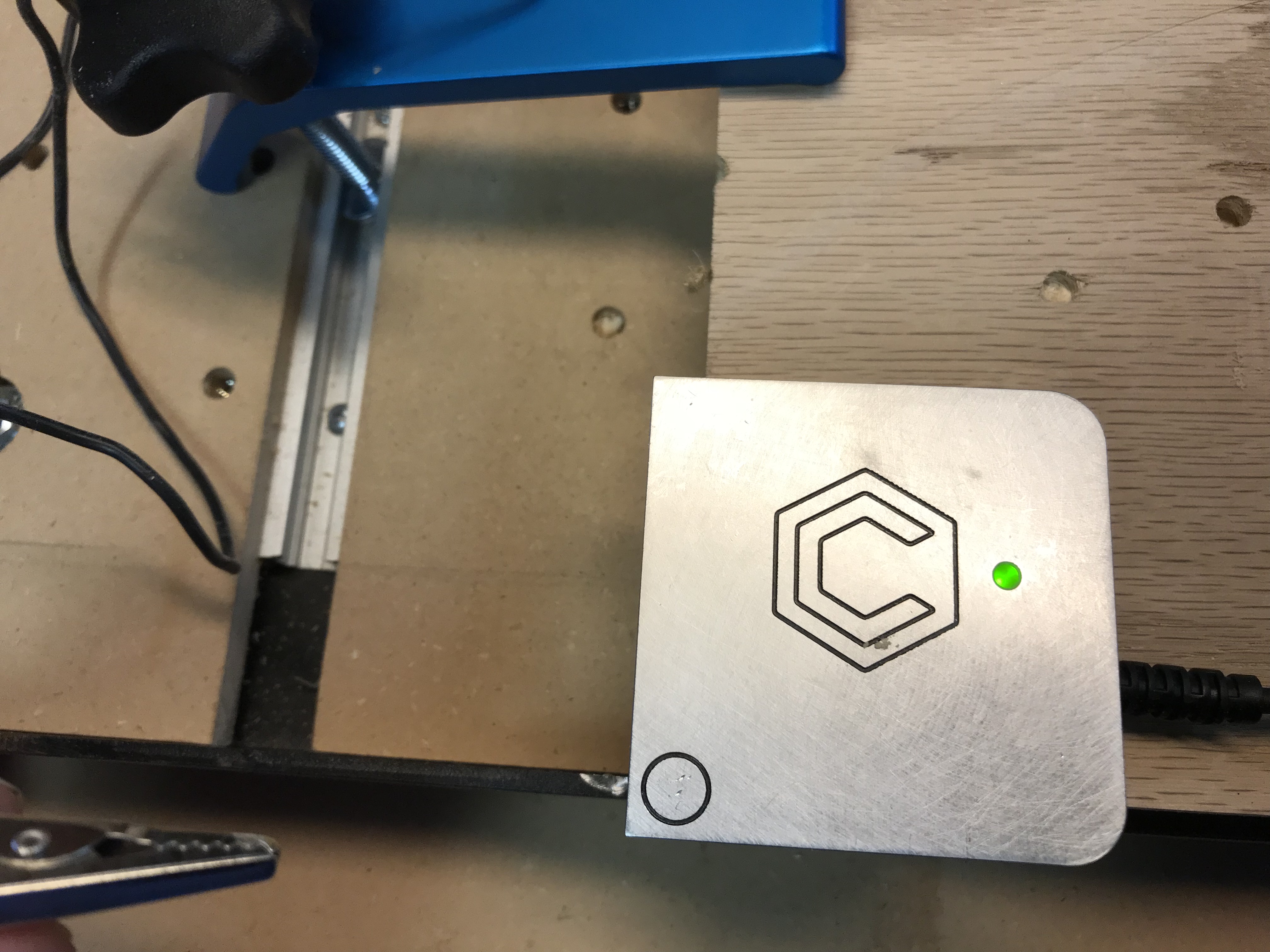
If you have the probe connected and the alligator on the bit, what does the LED do if you raise the probe upto to bit?
Griff
(Well crap, my hypometric precursor device is blown…)
13
When I have the cutter positioned above the target at 1/2 “ and the clip on the cutter I pick up the probe and touch the cutter, red led. When I initiate the probe cycle the led turns red upon cutter contact but the spindle continues to descend. I think what we have here is a failure to communicate.
Make sure the cutter is not too high, while probing the Z it will only move down 12mm or so.
I lowered the cutter to 4 or so MM above the probe and started again and all went well.
The actual location was 1/4 off the corner. Kind of assumed that knowing the diameter of the bit and the offset of the probe itself that the X and Y zero would be where I would manually put it at right on the corner of the piece.
No biggie, but just something to keep in mind.