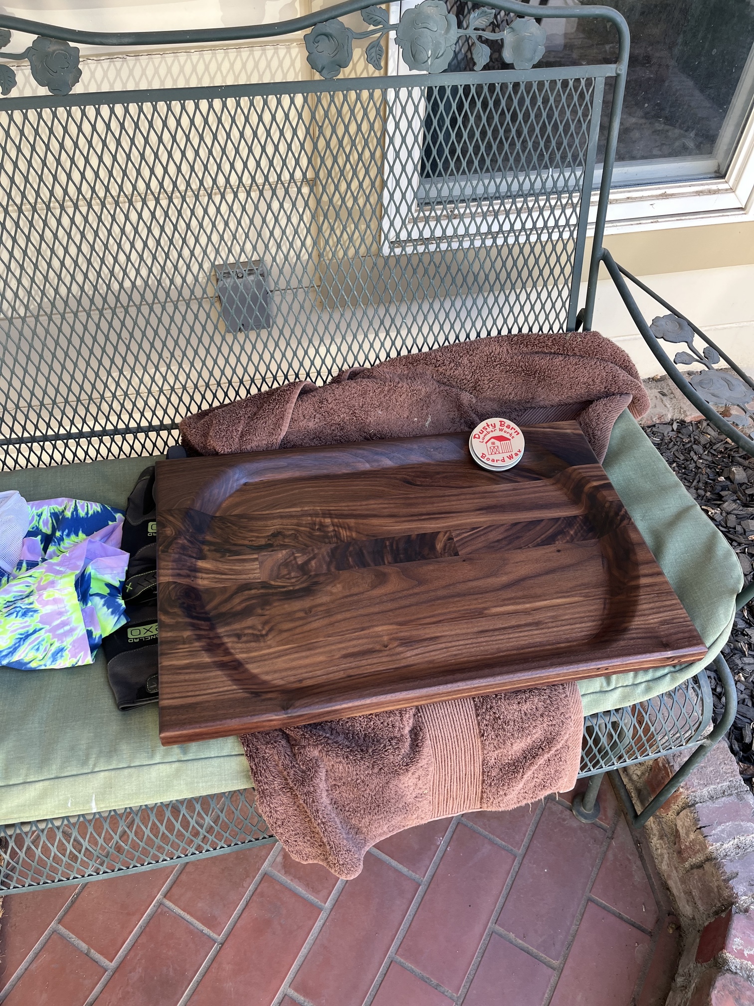
I recently got a Shapeoko 4 xxl and one of the main drivers was to help me make
These trough cutting boards faster. BUT I can’t seem to get the file built correctly I. Carbide crest pro. I want it to slope down around 45 degrees from 2” to 1” thick the. Be perfectly flat. Can someone help me figure out what I’m doing wrong?
Please post your file here or to support@carbide3d.com and let us know in what way it isn’t working out.
Well I don’t know how to create the file in pro to start with. It looks like I need some kind of greyscale drawing for the slope (which I’m not sure how to do) and I def don’t know how to make the bottom 1” flat.
The times I tried I added inside ovals 1/4” inside consecutively and tried to run the tool paths deeper each layer, but there are way too many ridges and the slope isn’t even.
To get 45 degree angle slopes:
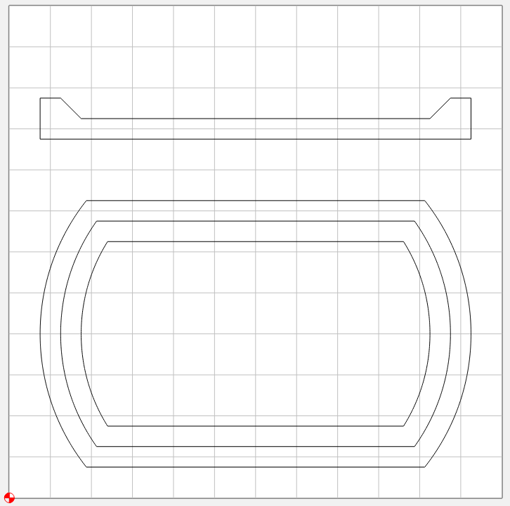
- draw things up in profile:
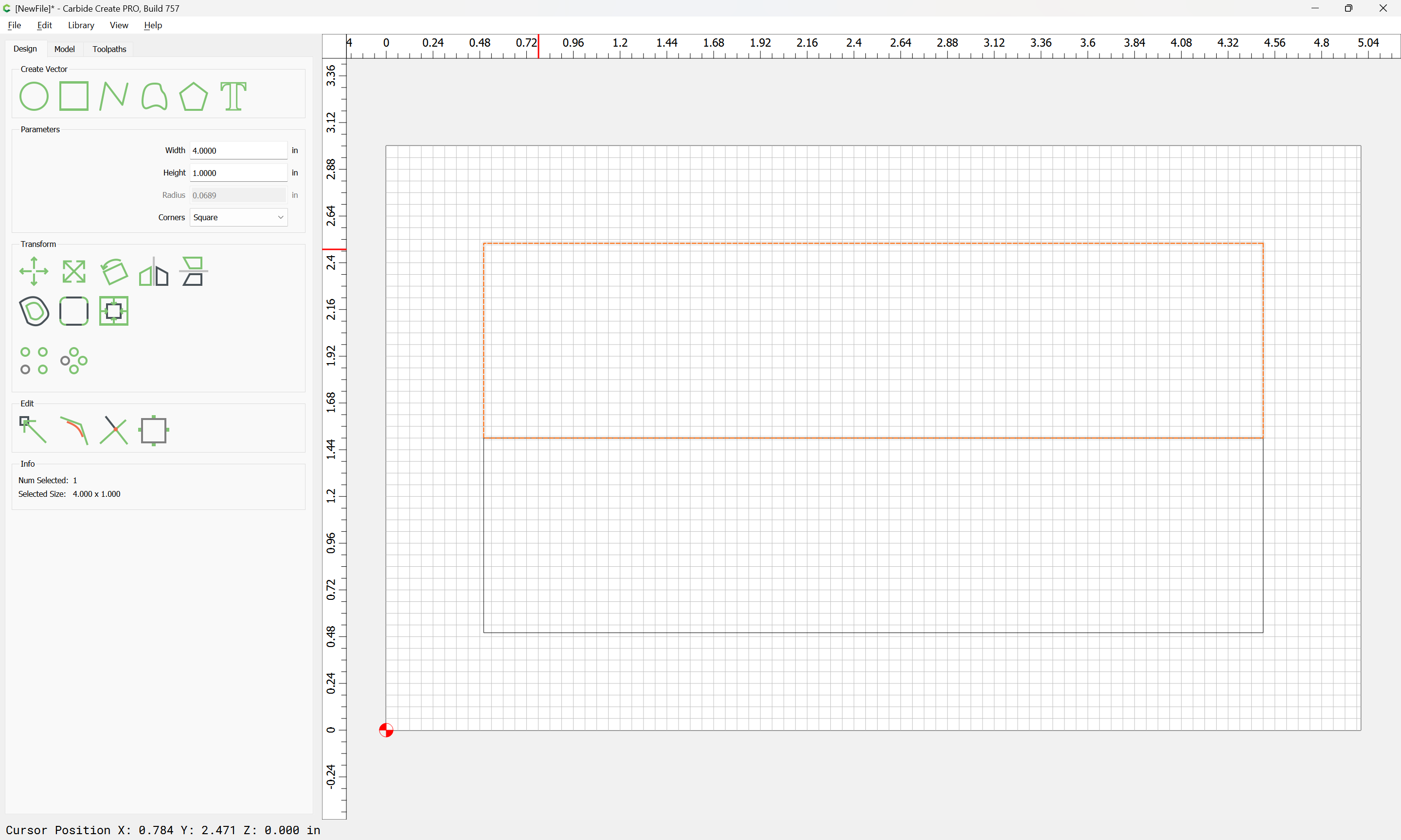
Noting that one needs 1.413" distance to get a 1" thickness at a 45 degree angle, draw things up:
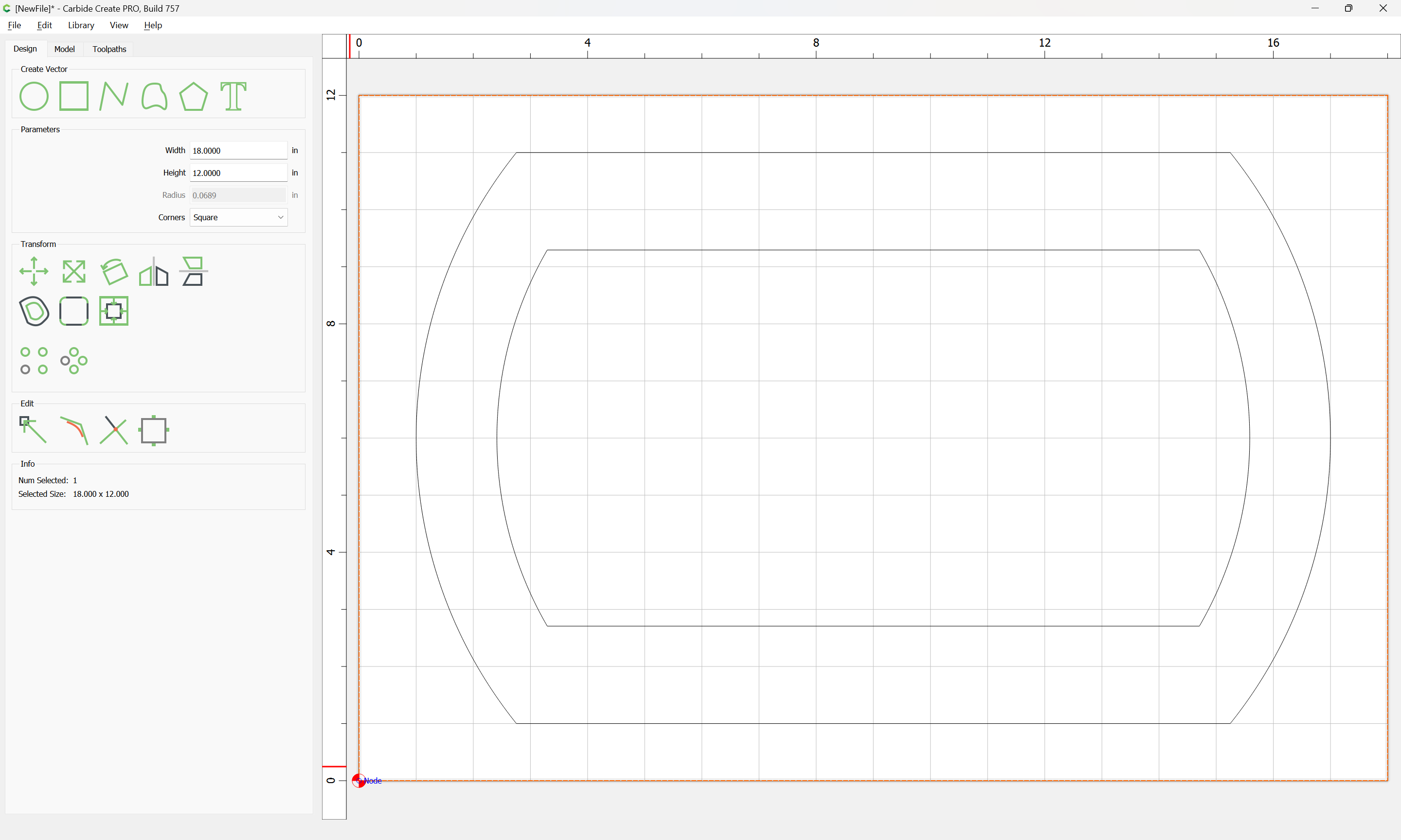
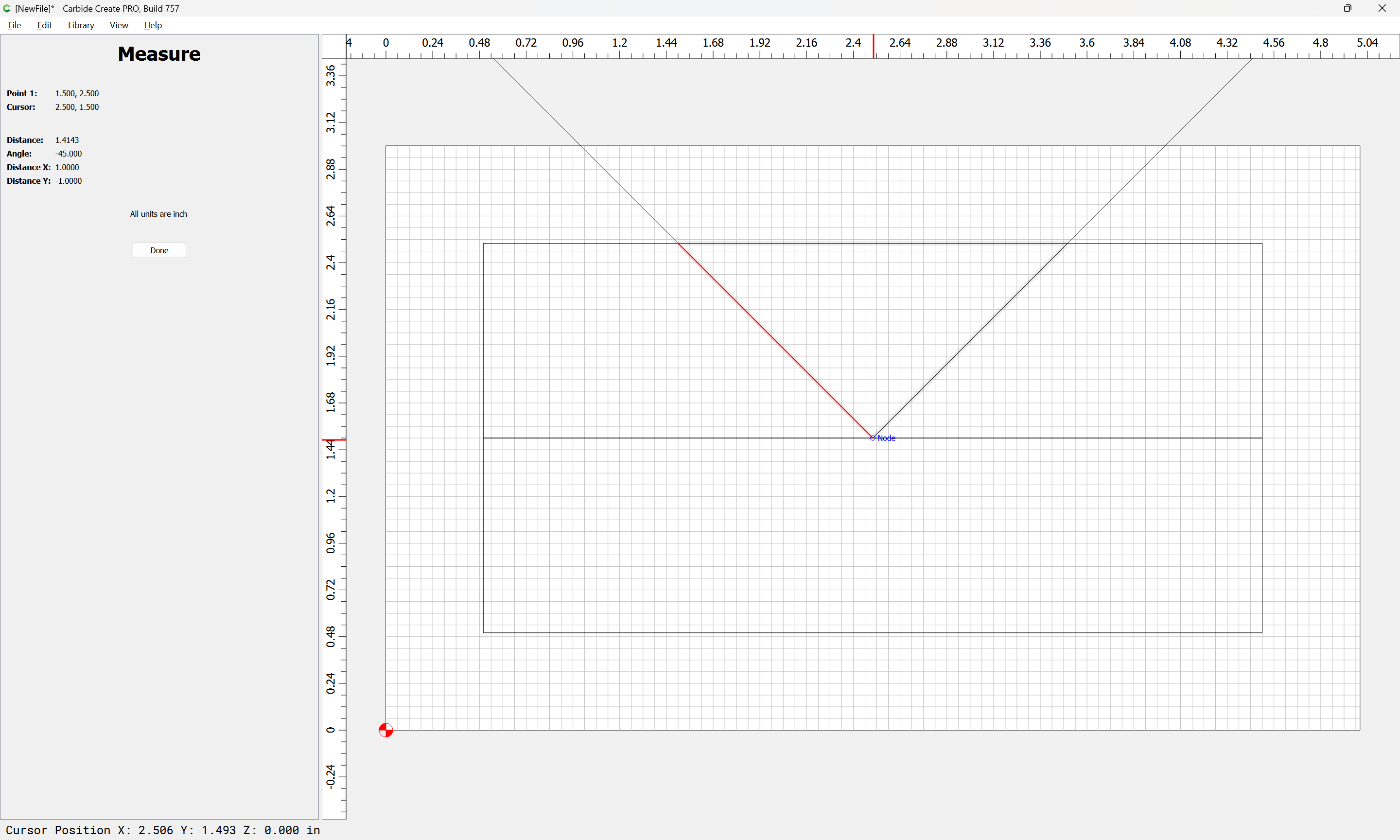
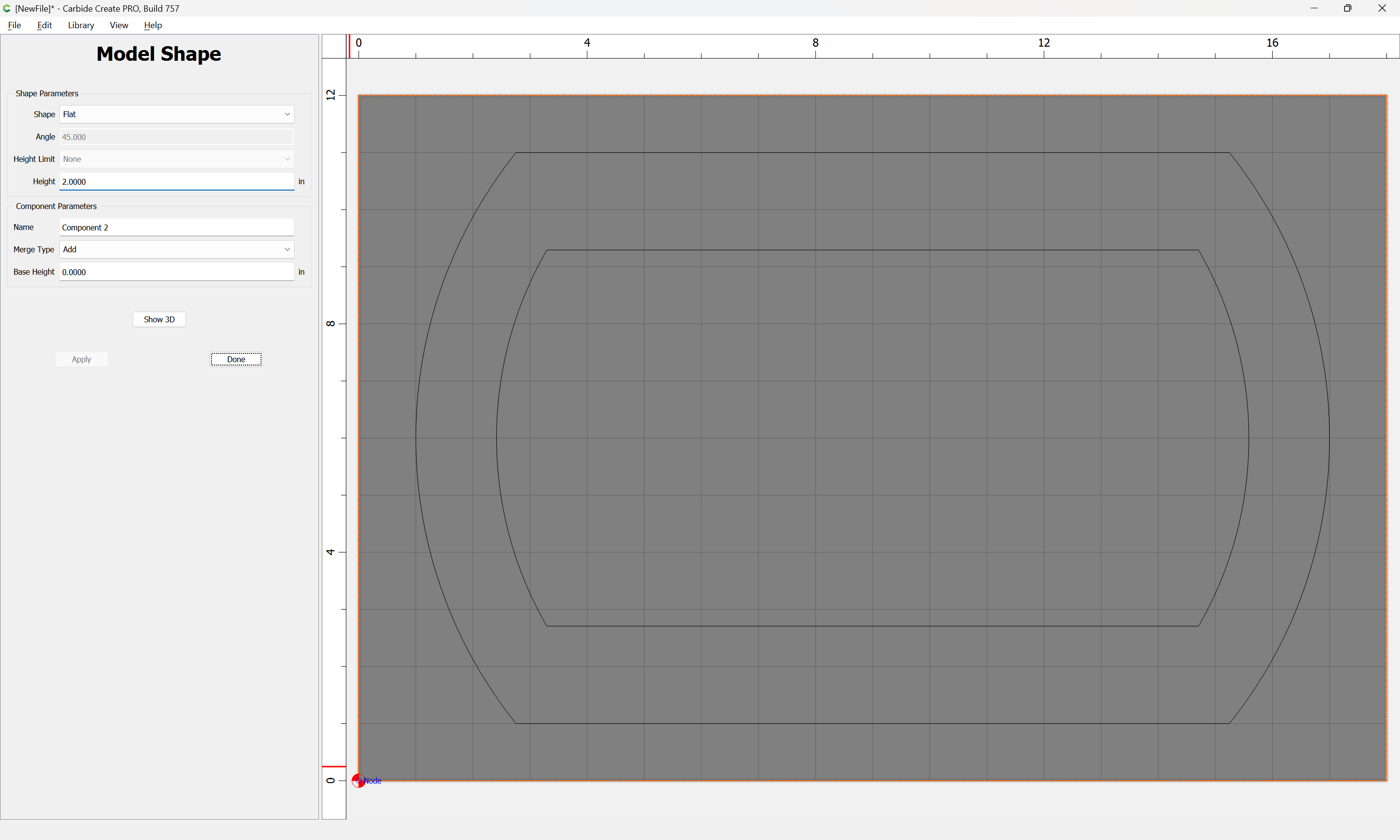
Then model the 2" base thickness:
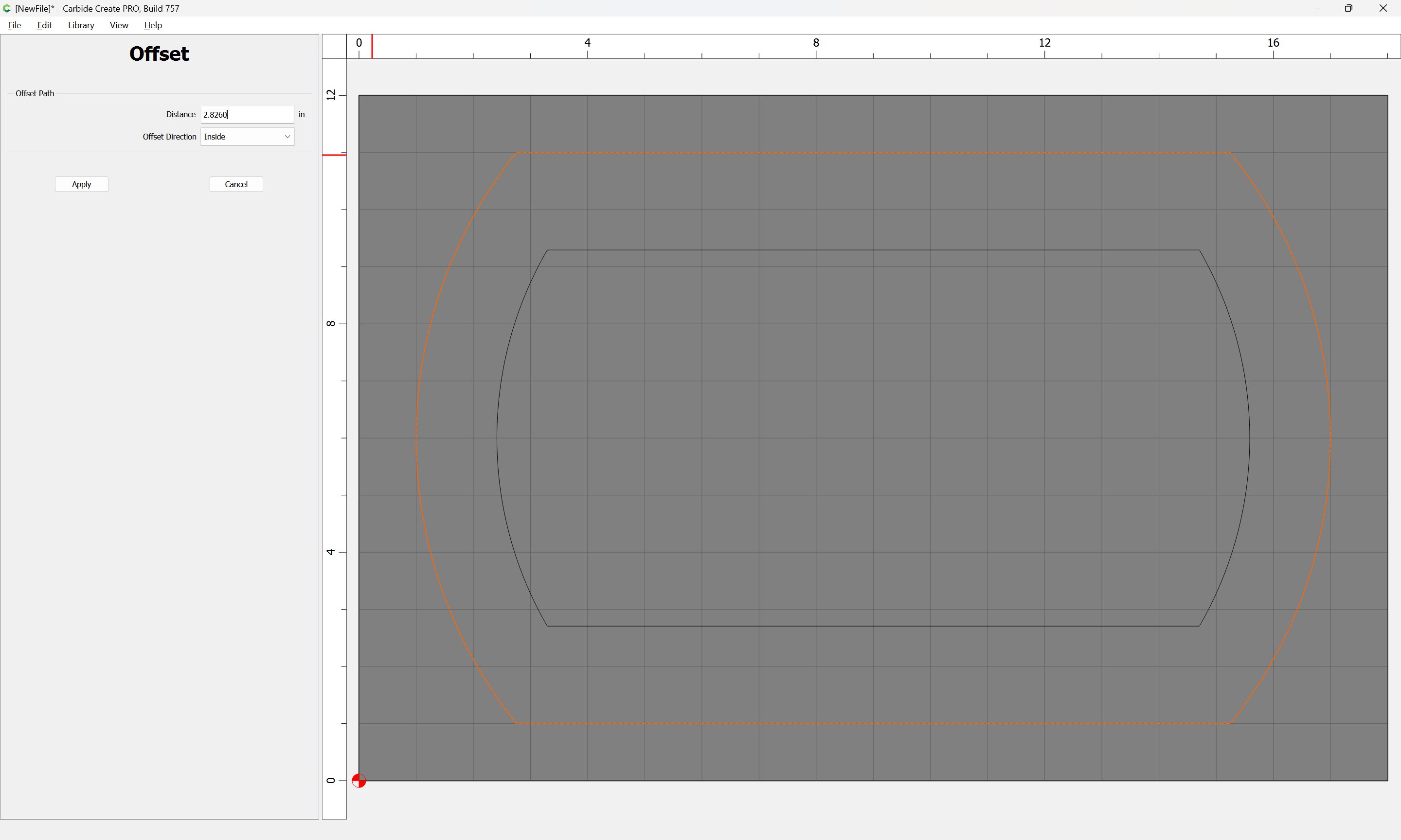
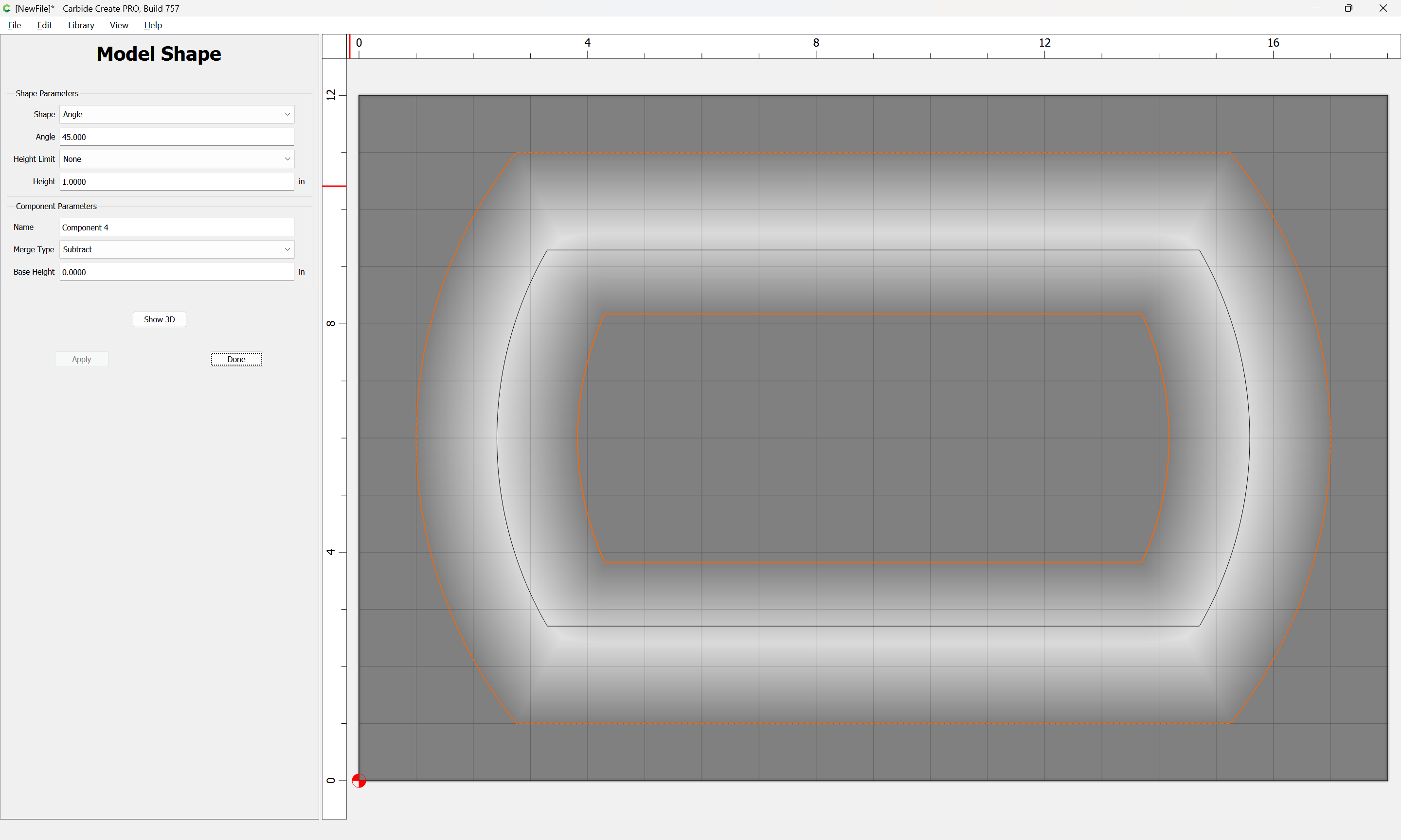
Then subtract 1" at a 45" angle using a 1.413" width doubled:
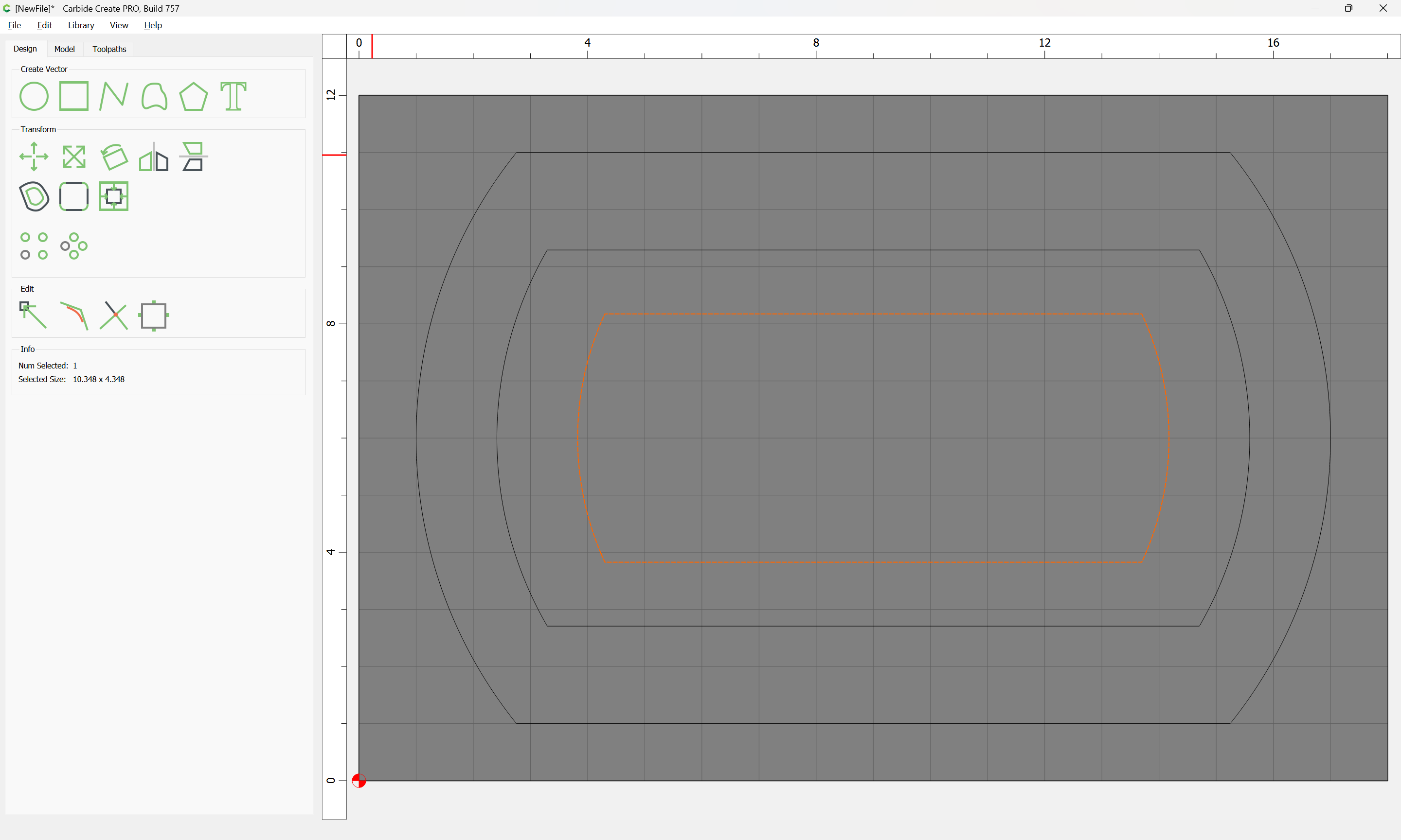
Then flatten the bottom:

The geometry needs a bit of adjusting:

but that’s the basic concept.
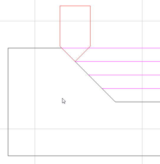
Alternately, you can directly draw the geometry and assign suitable toolpaths:
Or, you could use a vector drawing program or other graphics tool to create a depth map which matches what you want, see:
If you have difficulties doing any of the above, let us know here or at support@carbide3d.com and we will do our best to walk through things with you.
2 Likes
Man you did that quick!
I can’t even figure out how to get it into profile view to start! Can i just pay you for the file? Jk…
1 Like
There is no profile view. Only a top view. Make your workpiece bigger & just draw it off to the side like a projected or section view on a drawing.
At 1" deep, if your V bit can cut about 1/4" deep at a time, you could cut this as 4 advanced V-Carve operations at 0.25, 0.50, 0.75 & 1.0 deep
1 Like
If you will let us know all the dimensions in question we will walk through this with you step-by-step here in the forums.
As noted, there is no profile view — I just find it useful to draw things up thus as a reference.
Oh thank goodness! I spent an hour trying to find a damn profile view!
Will your response was extremely helpful. I never would have figured it out without your help. I think I got it done and messed with the toolpaths for a while. I did a 3d rough/finish using a 3/4" round nose bit and finished with a 1/4" ball bit. I’m not sure it will get me smooth sides with the bowl bit tho.
Also, I set my size, but now I cant figure out how to resize the model if i have a different size piece of wood. Is that possible or do I have to redesign the file each time I have a different size piece of wood?
Thank you all for your help!
Unfortunately, nothing is parametric. The height map (solid model) is not associative to the curves that create it, and you can’t edit or choose new curves. So you will have to remodel it to change the size.
I’ve started using a naming convention so I can later remember how I modeled each component.
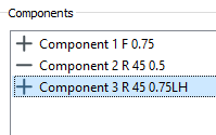
So the first one is Flat with a height of 0.75
2nd is Round 45° with a height of 0.5
3rd is Round 45° with a Limited height of 0.75
2 Likes
Thanks Tod. I can’t get the advanced v carve to look right. First it shows an oval with some spurs at ends and it also doesn’t angle the sides. What am i missing?
AND…we’re all hoping that the new version of CC Modeling is going to address being able to go back and edit the components…yes??? ![]()
Hope, yes. But as my Grandpa used to say, “Hope (Wish) in one hand, and crap in the other, and see which one fills up the fastest!” ![]()
1 Like
Not me, I’ll stick with Fusion 360, and Vcarve Pro.
This topic was automatically closed after 30 days. New replies are no longer allowed.