I recently got a new computer. I installed CC and CM on the new computer. I have S4 XXL with stock options. I set up the software and bit setter. I’ve done this serval times over the years with no issue.
I cut pockets out fine on my first carve. The contour toolpath kept cutting way past the bottom of the workpiece. It carved way into the wasteboard. I restarted the carve and it happed again.
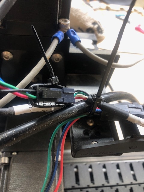
I had a few issues where this happened. Check your connections for the stepper motors. Pull them apart to see if it might be arcing. If they work free that will happen. I use a zip tie on mine now.
I looked at your file and would like to make a suggestion. This has nothing to do with your problem but may help in the future.
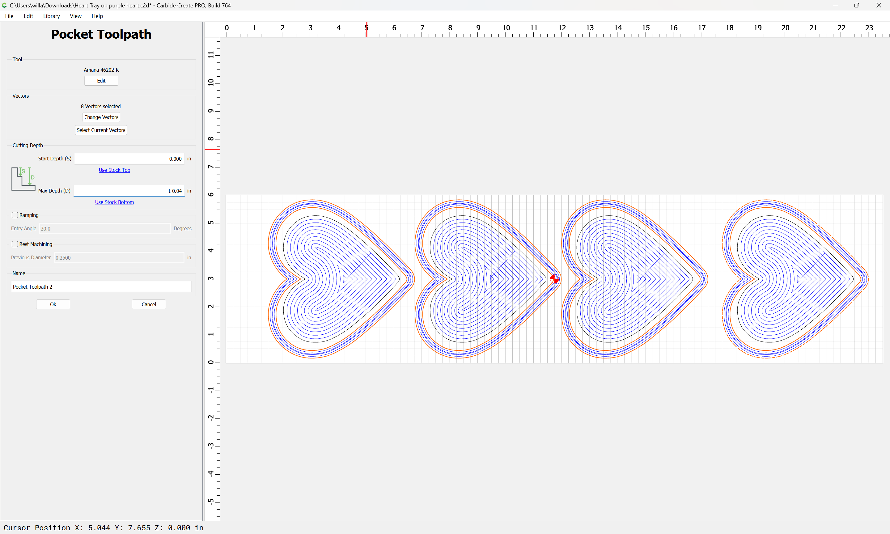
On your contour file you have the depth to .75". There is nothing wrong with that but when you want to cut all the way through use “t” instead. The reason is when designing you may be putting in the nominal depth but when you actually get the material on the spoilboard you should measure and change the actual material thickness in CC. By using “t” you do not have to go back and edit every tool path you put .75" in and the tool paths will automatically update to the new material thickness on a save. Additionally I like to use bottom of material on cut through tool paths and use the spoilboard to set up my Z zero. That method has kept my spoilboard almost pristine for almost 2 years. Most critical to not cutting through is to very accurately measure your material thickness and put the actual measurement in CC and then save. Estimating the material thickness or guessing can lead to cutting through the material and cutting up your spoilboard.
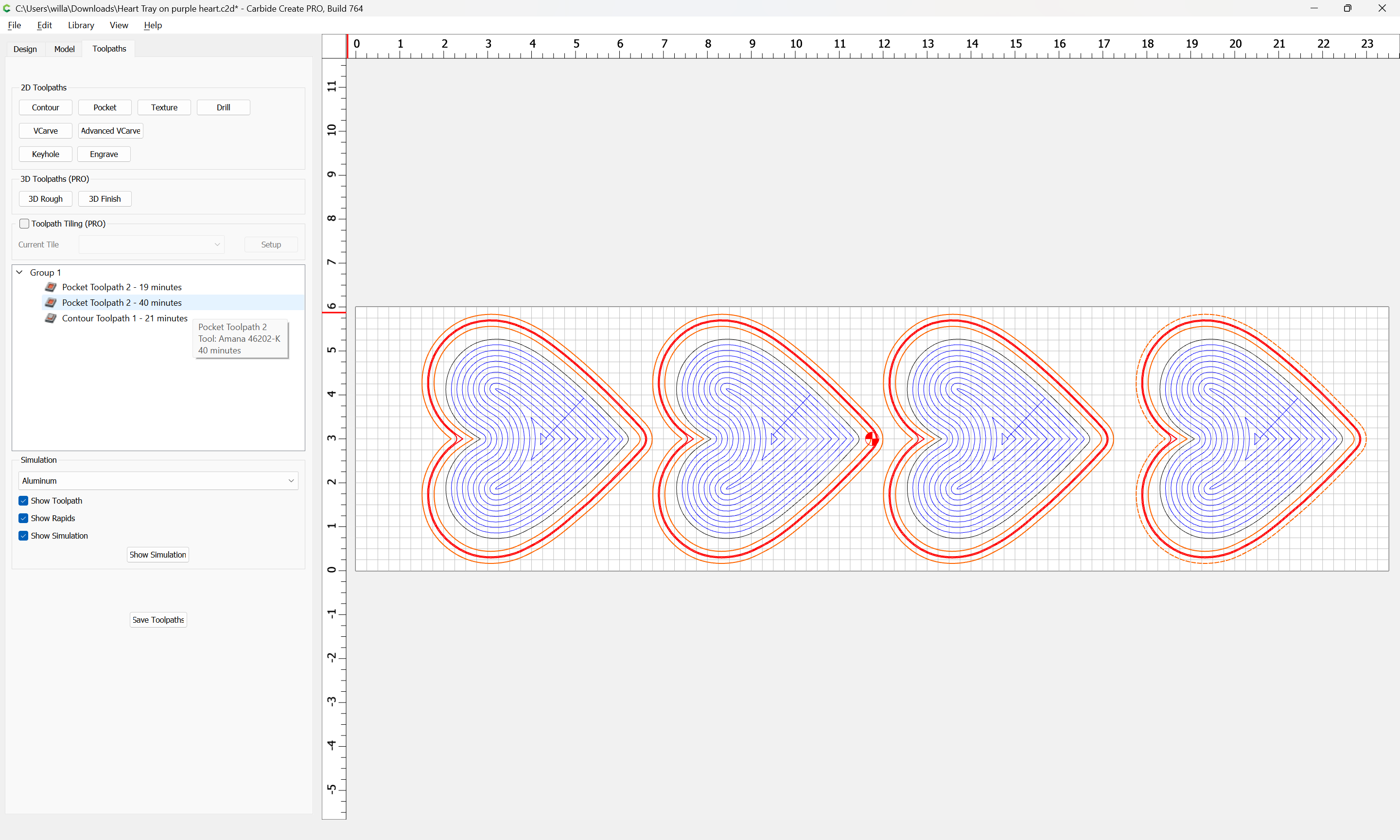
In your job setup you have your retract height at .5". Again nothing wrong with that but with a more complicated project that would take a tremendous amount of time to rise up and come back down adding a lot of time to your project. I usually use .125" or less for retract height and that keeps the extra time to retract and plunge to a minimum.
Note that all of the below assumes the machine is mechanically sound and well-lubricated and all wiring is in good condition and all connectors secure.
You are cutting a slot 3/4" deep using a tool which is only 1/4" in diameter, so you are cutting a slot 3 times deeper than the tool is wide.
This results in near constant high tooling engagement and can pull the tool into the cut.
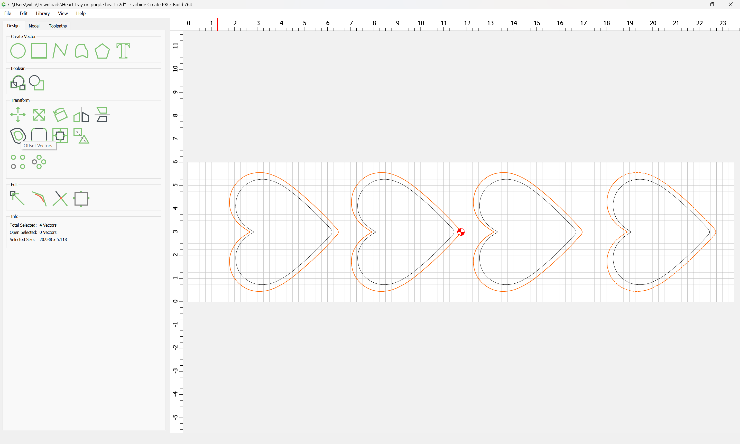
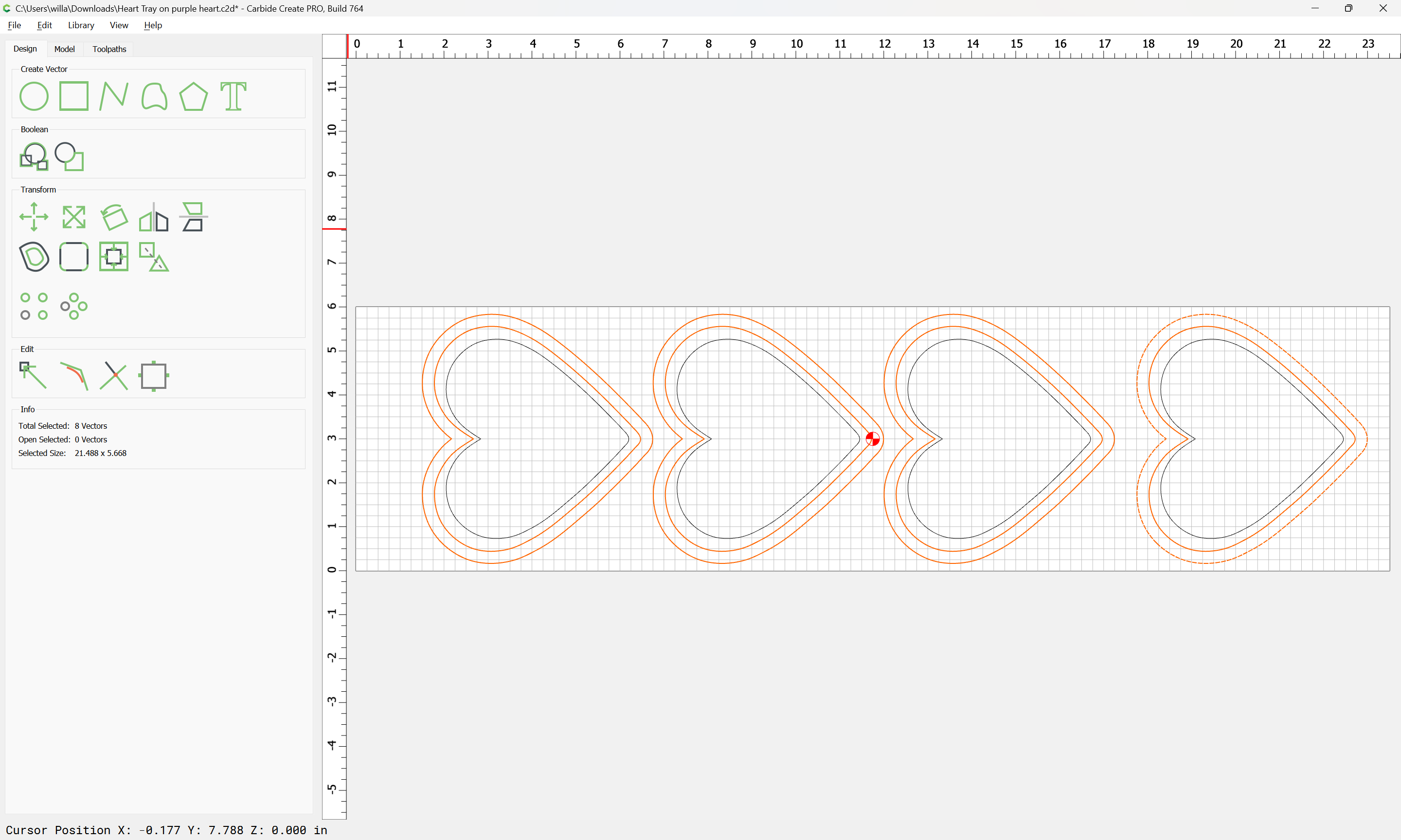
Optionally the contour may be changed to begin at the bottom — if desired you can offset to the outside twice and create a roughing clearance for a finishing pass.
Your file looks good. I’ve attached my version with a couple slight changes I would make.
Will makes a good point about the endmill being sucked downward. Upcut endmills can definitely drag themselves down in the collet yet still appear to be tight. Definitely give that a look.
Guy is dead on with use of “t”. It’s one of the best small features we have in Create. I use “t+.1” (mm) in all of my projects. (.1mm = .0039") The expression would then be “t+.0039” for your max depth on the contour cutouts.
My typical retract height is 3mm.
Re: Cutting 3/4" wood with 1/4" tool - I do this all the time. As long as your endmill is secure and your workholing is on point, you’ll be fine. I see you arean’t using tabs. Do you have double sided tape or tape and super glue in use on this cut?
Always remember that CNC is all about learning. Cutting your waste board a few times and even messing up some t-tracks is totally normal. Our machine at HQ also has some battle scars.
I’m not sure I’m clear on what “t” is. I have never used that feature. Can you explain? Sorry for the lack of knowledge.
The tab part brings up an interesting point. I do have tabs in the design, but since the depth was plunging so low they never got a chance to cut. Basically would have been cut into the wasteboard if anywhere. Any idea other than the depth why the tabs wouldn’t cut?
T = the thickness of the material defined in the setup screen.
Using that since because of you run the same job but have a different material thickness you change it in the setup screen only and leave the paths alone.
To tag on to what everyone above said. “t” is a reference to the stock thickness you define in Job Setup. So if your stock is .75" one day and then you change it to .5" the next, you don’t have to manually edit your tool paths, they update automatically when you define the new stock.
An added benefit is being able to specify the max depth of a toolpath you want with an expression. For example “t-.0315” would leave a ~1/32" onion skin layer on the bottom of your cut to keep your parts from coming loose if you didn’t want to use tabs. And “t+.0315” would cause your toolpath to cut ~1/32" below the stock.