Julien and ColdCoffee, Thank you. I will experiment with both approaches. Great help!
fenrus, I look froward to seeing what you come up with.
Again, this groundswell of help is amazing!
Julien and ColdCoffee, Thank you. I will experiment with both approaches. Great help!
fenrus, I look froward to seeing what you come up with.
Again, this groundswell of help is amazing!
part is selfish… I’ve done 8"x12" landscape cuts before but thats the limit of lumber I tend to get (fits in a USPS box)… this would allow me to go MUCH bigger, which means more detail 
I certainly didn’t think it was all about helping me…just expressing my appreciation
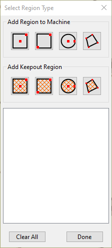
There is a feature in MeshCAM that @robgrz didn’t carry into Carbide Create that could have been useful here. MeshCAM has the concept of a “Machining Region” and a “Keepout Region”.
Thank you, Robert. I’ll take a look at that.
Very early version of the tool seems to be running, I still need to clean up a bunch of stuff and fix the GUI (which I will do next) but figured I should mention here the progress
https://fenrus75.github.io/FenrusCNCtools/stl2nc/nctile.html
list of known todo items:
I will give this a try ASAP. Thank you, fenrus.
found a weird bug that I just fixed
(I’m cutting some landscapes right now)
if you havent; started you might want to update
Mount Hood volcano in 4 tiles some pictures of the result
added ARC support (G2/G3) to the tool so now it can also deal with Fusion360 gcode I assume
Hi fenrus,
I finally found time to test your tool for tiling a heightmap. It worked perfectly! Thank you so much! I did a test that was 17"x17", four 8.5" squares. I’m at a bit of a loss for how to create gcode for the larger item I have in mind. The problem is that my heightmap measures 48x45, larger than allowable dimension in Carbide Create. I think I’ll be able to get access to Fusion360 in the near future, and that alone may solve my problem. Are there other avenues you can suggest? I’m typically using PNG or JPG files. Thank you, again.
Please see:
for the concepts on tiling large parts via smaller cuts.
So few options I can think of, but mostly questions
How do you get to the PNG in the first place? If this is basic geo data, you can start with an STL and then bypass Carbide Create and go from STL to gcode directly (as I did in my example)
What’s the resolution of your PNG? It would likely be a small tweak to the STL-to-gcode tool to also just take a PNG as input
Will, I think the question is that the design is too large for Carbide Create to create gcode for.
Tiling can be done after you create gcode with https://fenrus75.github.io/FenrusCNCtools/stl2nc/nctile.html which takes gcode for a large design and tiles it into smaller sections 
hmm there’s an option 3
I add a zoom option that lets you zoom X/Y (and probably Z) from the original gcode. That way you can design in carbide create at half dimensions, and the tool magnifies the gcode as part of splitting it. In terms of implementation, that’s the easiest of the options, couple of minutes kind of thing
Thank you, fenrus. First, I have PNG files because that is the output format I get after I take USGS info to QGIS to define my desired extent. Another C3D Community member created this QGIS/heightmap export tool some time ago. As for the resolution, my PNGs are initially always 72dpi x some large dimensions (on the order of 50"x50"). I typically convert them to a more moderate dimensions at 100-250dpi, depending on desired detail/refinement. I welcome any suggestions for alternative ways to acquire and refined data, and I’ll take a closer look at the process you followed for Mt Hood. Also, if you modify your STL to gcode tool so it handles PNGs too, that would be great. Your help is allowing a guy with tech limitations to get fewer bruises on the head. Much appreciated!
I’ll take a look
one thing to always track is that you don’t pixelate the result; if your png is too few pixels and you make it 50"x50" you’ll be able to see the individual pixels in the final result.
ok I think that the easiest thing to do is make a small tool that converts such PNG to an “STL like file”… which then can go into the other tool for turning into gcode and then for splitting.
the one thing that keeps worrying me is how much “height” is there in a pixel, there must be some amount of metadata for that somewhere… so I wonder if you could get me an example file of sorts… I could also always just make it a GUI input box I suppose.
(“STL like” since it’ll be STL enough for any of my tools, but it might not strictly comply to the STL specification)
Hi fenrus,
https://drive.google.com/file/d/1c6NIRA5cx0UyZCG47sbcVwxbEy7hhc6F/view?usp=sharing
Here is a link to a PNG that I’m working with. It is 100 dpi and 48"x62, minimally modified in Photoshop after download from QGIS. I hope this method of sending and the doc itself work for your purposes. If not, let me know, and I’ll provide alternatives. Thank you!
got it… I wonder if Photoshop removed any Z scaling info
Image Width: 6242 Image Length: 4800
Bitdepth (Bits/Sample): 16
28M pixels… not insane (but STLs have a 2M to 4M triangle limit, I’ll figure it out somehow I hope)