I have a heightmap of some mountainous terrain (USGS download, processed in QGIS, sized and cut into pieces in Photoshop) that I’ve divided into twelve even pieces. I’m not sure what the best way will be to achieve elevation continuity across the twelve tiles given that each tile will have a unique high and low. Any ideas? Thank you!
Hi David,
Not sure I get what you mean by
I understand you will be cutting 12 individual tiles, one at a time, and maybe the stock thickness will be slightly different from one stock piece to the next ?
I would setup the CAM to zero off the bottom/wasteboard, to have a consistent Z reference used to mill each tile?
I think he’s looking to have terrain split over 12 tiles. Likely because the size is too large for the CNC?
I think if you duplicated the high point of the image in an area outside where the cut tile is, so that the tallest point is referenced in each picture, but that you’re going to cut out away from. Hopefully that makes sense? That way your tallest point is referenced when using the grayscale height.
or maybe @fenrus has all the right software pieces in place to start from a unique giant heightmap, and generate 12 individual G-code files from it. Let’s see if I can trigger him 
I see two fundamental paths to do this
path 1) Within Carbide Create Pro (or equivalent)
Make one huge 3D model for the heightmap, but in the toolpath section, only create toolpaths for a subset “square”, and for the 12 tiles, you move the model so that you get 12 different paths. Because it is only one 3D model, the heights will be consistent
path 2) a gcode tiling tool
I dont know if one of these exists, but building one is very viable and maybe an hour or two of work.
The flow would be to pretend that you have one huge work with whatever CAM you use normally and generate gcode. Then the tool would split this gcode into the 12 tiles and outputs 12 separate gcode files that you cut separately.
Again consistency happens because the tiling only impacts the X and Y coordinates and will leave the Z coordinate alone.
With a holiday (US) coming up I might just build such a tool while waiting for epoxy to harden in my cold cold basement 
This Split the XY, leave the Z alone tactic is exactly what Vectric VCarve ‘large piece tiling’ options does. I’ve used it to carve a single artwork across a pair of doors, each door on the 3XL at a time, and it works brilliantly - they cater for a degree of overlap to give trimming leeway on the cut pieces prior to fitting/glueing together.
Triggered ! ![]()
Joke aside I could definitely see myself needing such a tool, for tiling 3D jobs that my SO3 work area can’t handle in one go.
would you want the tool to also create some gcode to cut out the tile? (basically an outside contour pass)… Yes one can use a table-saw for this but why not use the CNC machine for it ;)(
This is the direction my mind went, and I used this process for the finishing pass on this map. Not because of tiling, but more for scheduling time.
The complication I see when making different tiles/sections is that each section (of the topographic map) would need a different zero point if they were being cut on different stock, or do as you suggested and move the map (in carbide create) for each section.
Each cut would need a proper X/Y zero (while leaving Z alone if all the stock is same height)
but I see no way around that
(the tiling would move the tile always to start at 0,0 obviously)
Absolutely, as long as you allow for a different tool to be used for the cutout ![]()
Wow! I’m overwhelmed by how responsive and helpful this community is. Thank you all!
I can certainly establish 12 separate vectors in a single heightmap, as suggested by fenrus. I’ll also look into Vectric VCarve as suggested by AndyC.
To verify understanding–
Will I be good if I do the following:
- create one large job with 12 separate vectors
- run gcode for each vector/toolpath separately
- establish z 0 at bottom
[I use CC Pro for this; no experience elsewhere; is that okay?]
Question
Am I correct the x/y 0 can be the same for all 12 tiles, or is an adjustment required for this to work properly? I will place all 12 pieces of stock in the same location throughout.
To clarify–
My stock dimensions are identical for all pieces of wood. The “low and highs” I referred to earlier pertain to the peaks and valleys in the terrain and that each tile will have different high points and low points in that respect. Also, I am tiling this layout out of a combination of design intentions (artistic decision making) and ease of stock preparation. Each tile measures 8"x22.5"x1.875". Each tile will hang vertically in a six (horizontally) by two (vertically) arrangement. They will be space apart a bit, ultimately measuring overall a little more than the material dimensions (48x45).
I’m pretty new to the cnc and shapeoko world. Your help is soooo much appreciated. Thank you!!
next option is wait a few days until I finishing (well and start) on the tool to tile any gcode 
so question (before I build the tool)
would you rather enter the size of your tile into a tool (and have the tool calculate how many tiles you then get) or would you enter the number of tiles and have the tool calculate the size of each tile.
(it matters most for the last tiles; the tool would evenly distribute while by specifying dimensions the last tile could end up as a “half tile”)
Wow, again!! Thank you, fenrus! Either way of defining tiles could work for me. I lean somewhat toward entering the tile size, but by adjusting the size of the overall scheme the the “tool calculated” size can be made to conform to whatever stock size considerations may exist. I defer to your judgement. I’m blown away by what you propose to do.
While @fenrus brews his magical code, let’s give it a try in Carbide Create Pro in the meantime:
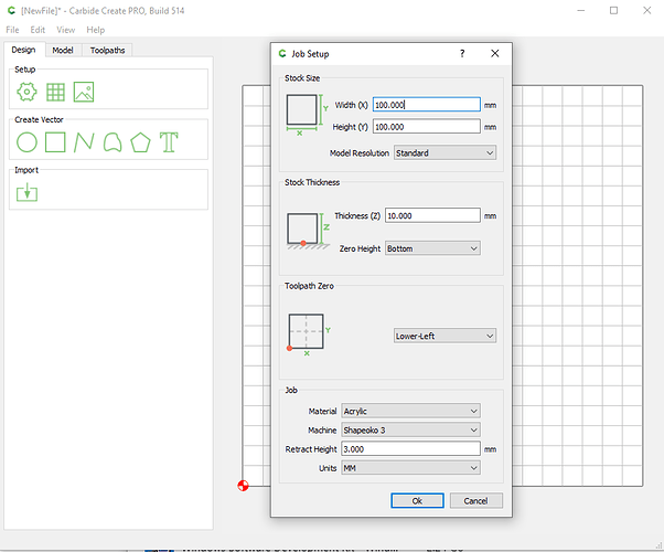
- I’ll create a sample project that would be only 4 tiles, 50mmx50mm stock for each tile, for a total 100mmx100mm area, and I arbitrarily picked 10mm for stock thickness.
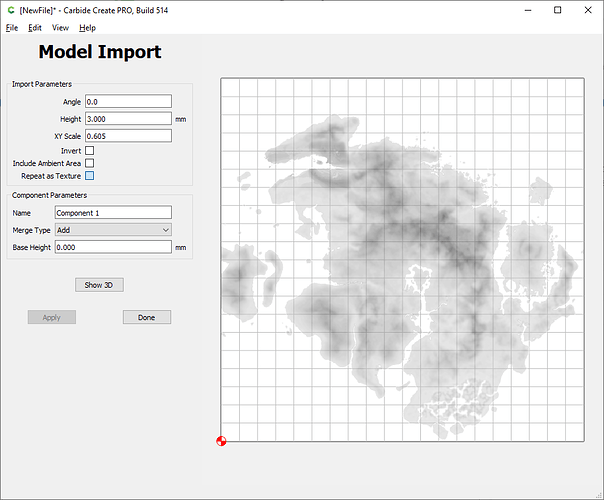
- Then I import a random grayscale heightmap I found, and scale it so that it fills the full area
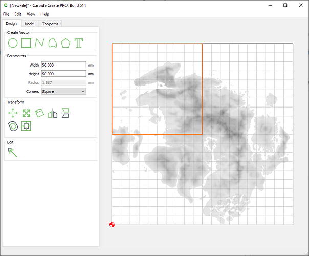
- Then create a 50x50mm square shape for the upper left quadrant
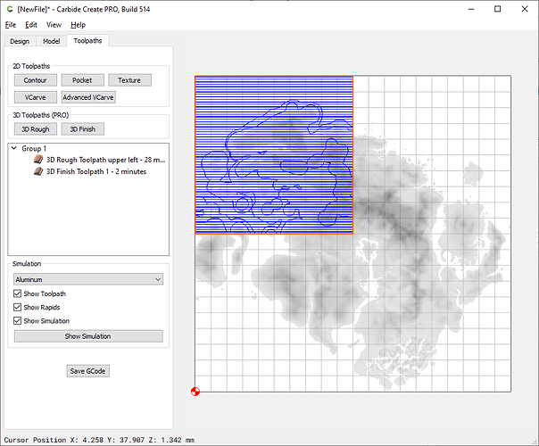
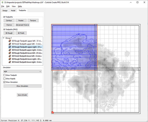
- With that shape selected, create the 3D roughing and 3D finishing toolpaths for that quadrant:
-
Repeat for the other three quadrants.
-
However I’m not quite sure how the toolpath edge conditions are managed, so to be sure the endmill will cut the full quadrant with clean edges I would choose to use a slightly larger rectangle than required for each quadrant, to “overcut” the boundaries. In reality this will overcut…air, as the stock is exactly 50x50mm in this example, but at least I won’t have to worry about the toolpath stopping a fraction of a mm short of the edge.
-
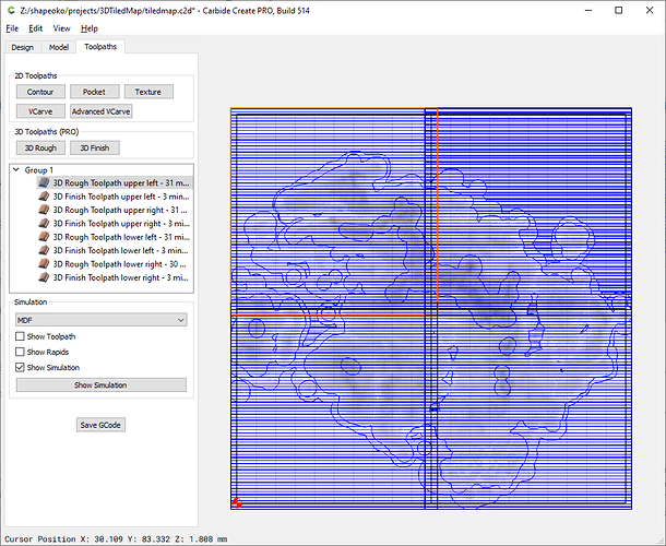
So I would end up with four 50x50mm squares, and four slightly larger squares centered on those, and one 3D roughing + one 3D finishing toolpath using those outer squares as boundaries:
-
finally, disable all toolpaths except the 3D roughing and 3D finishing for the first quadrant, and save G-code file #1:
-
then enable only the roughing and finishing toolpaths for the second quadrant, and save G-code file #2. Do the same for the third and fourth quadrant to create G-code file #3 and #4.
-
you end up with four G-code files, one per quadrant/tile. BUT! they all share a common zero reference of the larger work, which in my project is in the lower left corner, so for cutting the four pieces, I would do the following:
- for cutting the lower left quadrant, install stock #1, zero on the lower left corner of the stock. A corner/jig would be helpful to locate all pieces of stock in the same place. Run G-code file #1.
- for the lower right quadrant, install stock #2 it in the same location where stock #1 was, return to X0,Y0, but then jog left by 50mm, and reset X0 only. Run G-code file #2
- then for the upper right quadrant, install stock #3, return to X0, Y0, jog the machine to the front by 50mm, and reset Y0 only. Run G-code file #3
- finally, install stock #4, return to X0, Y0, jog the machine to the right by 50mm, reset X0 only, and run G-code file #4
The principe is the same for 4x3 tiles, but the values I mentioned above must be adapted then.
So this is doable, but that’s where @fenrus future tool will shine, it will remove all the tedious work of creating 12 square areas and toolpaths and g-code files manually in CC 
Thank you, Julien, for your example. It is so helpful. It lays out exactly what I envisioned and answers the x/y 0 adjustment question. I’m inclined to wait for fenrus’ tool, but is there a way to manipulate the x/y 0 to allow doing the process you have outlined on a set of tiles tha exceed the working space of the machine, in my case an XXL?
Right, my simple method won’t work then. You can still create toolpaths beyond the work area limits, but the zero will end up being too far to be set. You would have to use a different approach then, maybe something like:
- Setup work area to 50x50, zero reference in lower left
- draw a single 50x50 rectangle boundary
- while importing the map use a scale factor such that the heightmap is larger and an X,Y offset value so that the area that falls in the square is the desired sub-tile
- generate toolpaths for that tile and slave g-code.
- delete map, re-import it, using the same scale factor but this time using different X,Y offset, to match another sub area, then generate toolpath and slave g-code
- rinse and repeat for each tile
It will take a little thinking to figure out what import offset to use each time, but you would end up with a set of g-code files to run that all start with X0 Y0 in the same place.
Or maybe it’s just too late and I’m sleepy and someone else will point out an easier way 
Not claiming this is a “great” method, but I can confirm that it works. However you have to be careful and do some math.
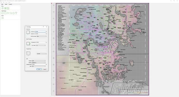
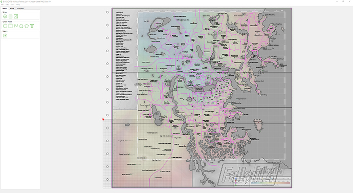
You can make one big map, at whatever size is needed.
After saving that (you want to keep the unaltered original). Alter the stock sizes (for this example I went down to 8x8). Notice the grid is only in the lower left area now.
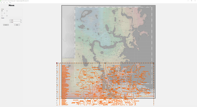
Select ALL objects (Cntl+A) and then choose the Carbide Create Move tool.
I wouldn’t trust moving this by hand/mouse, but you can key in positions for whatever corner and move a section of your large map onto your stock (this is where some math might be needed).
It won’t move the background image, but it does move the objects. Which you can then generate a toolpath for only that selection, and do a save-as so you don’t mess up the original.
so building a tool that just offsets by X/Y that you input on a webpage is maybe 15 minutes of work. I can do that first  (but I rather work on the tiling one, it’s more interesting to code that)
