Endmill cutting oversize so your offsets end up wrong? cut a simple drill operation 3/16 deep in the material you’re cutting then measure (ideally pin guages but you don’t have them so calipers) whatever size you measure above the nominal size of the endmill used is your offset on the outside right, inside left.
Cutting deep slots is not a good approach to achieve accuracy, which is why the usual test has one removing pockets:
If the dimensions of that test don’t work out well with endmills which are verified as to dimension on a machine in good mechanical condition, then see:
Understood! So far I almost never did precision work, toys etc. always just need to fit in relation to each other.
So the bits’ cutting edges pull away the bit from the designated path, obviously. And that depends on the kind of bit, every bit is different I am afraid?
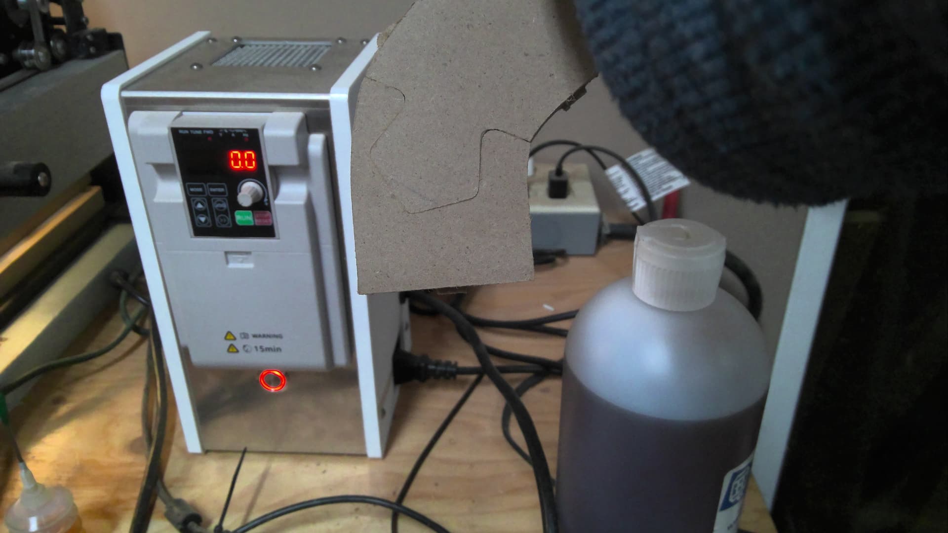
William: did a brief calibration test, X- and Y axis are precisely calibrated, did not Z yet, but was not the problem here.
Will test geometrical shape precision soon.
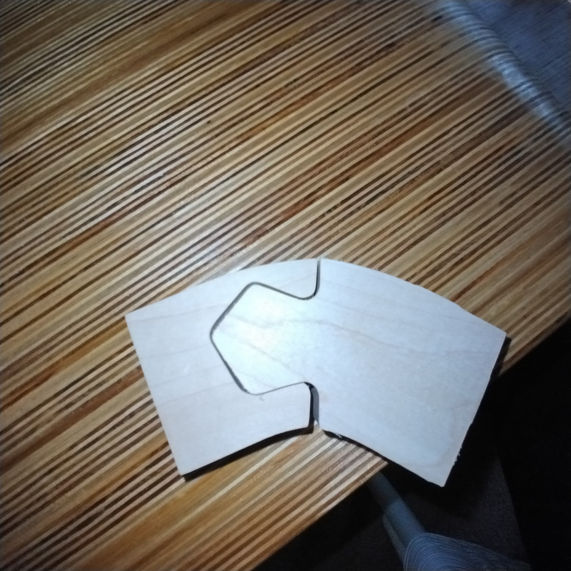
But I rather think it is all about specifics of bits deviating from the designated path depending on their cutting edges, so I will try next cutting the edges as pockets and not straight through.
Will take a little, probably next WE. But I will keep you posted.
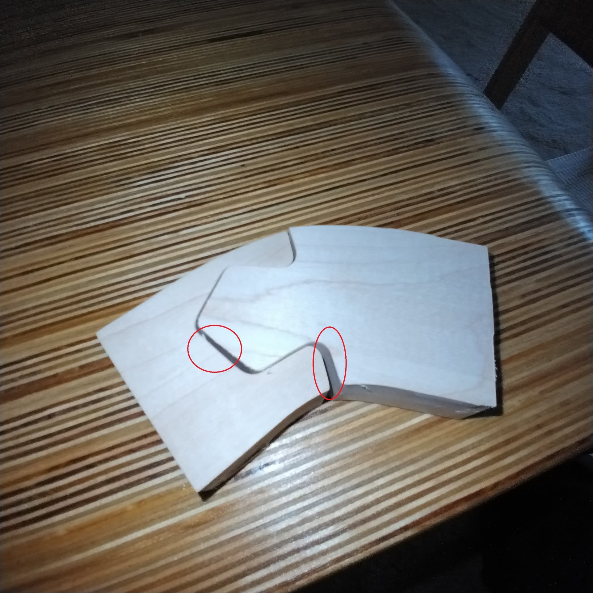
So, either something needs adjustment, or the cuts are too aggressive and are deflecting.
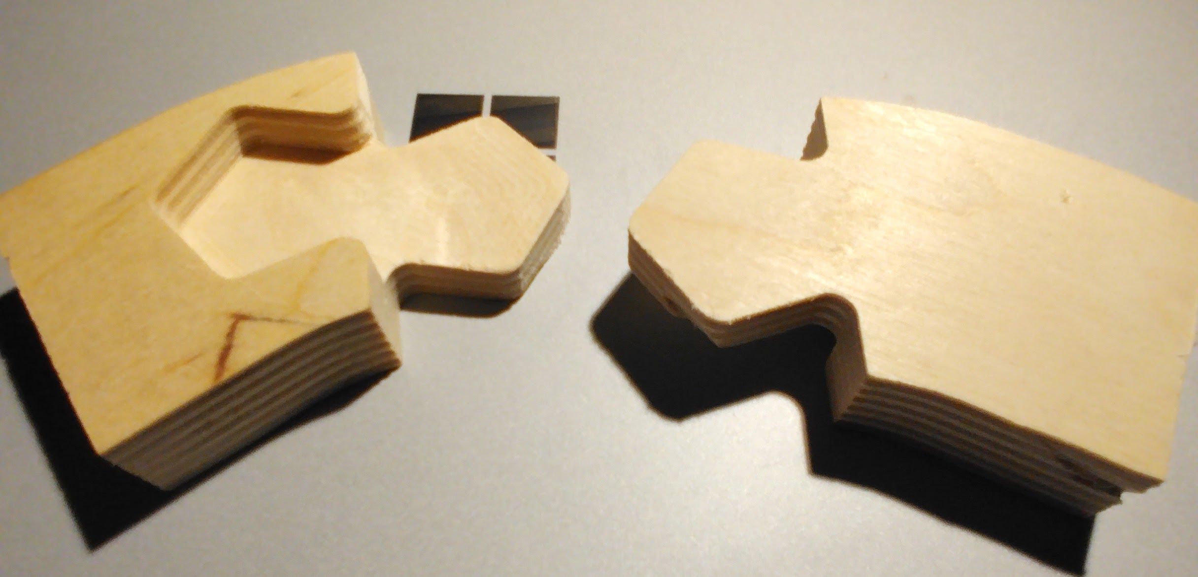
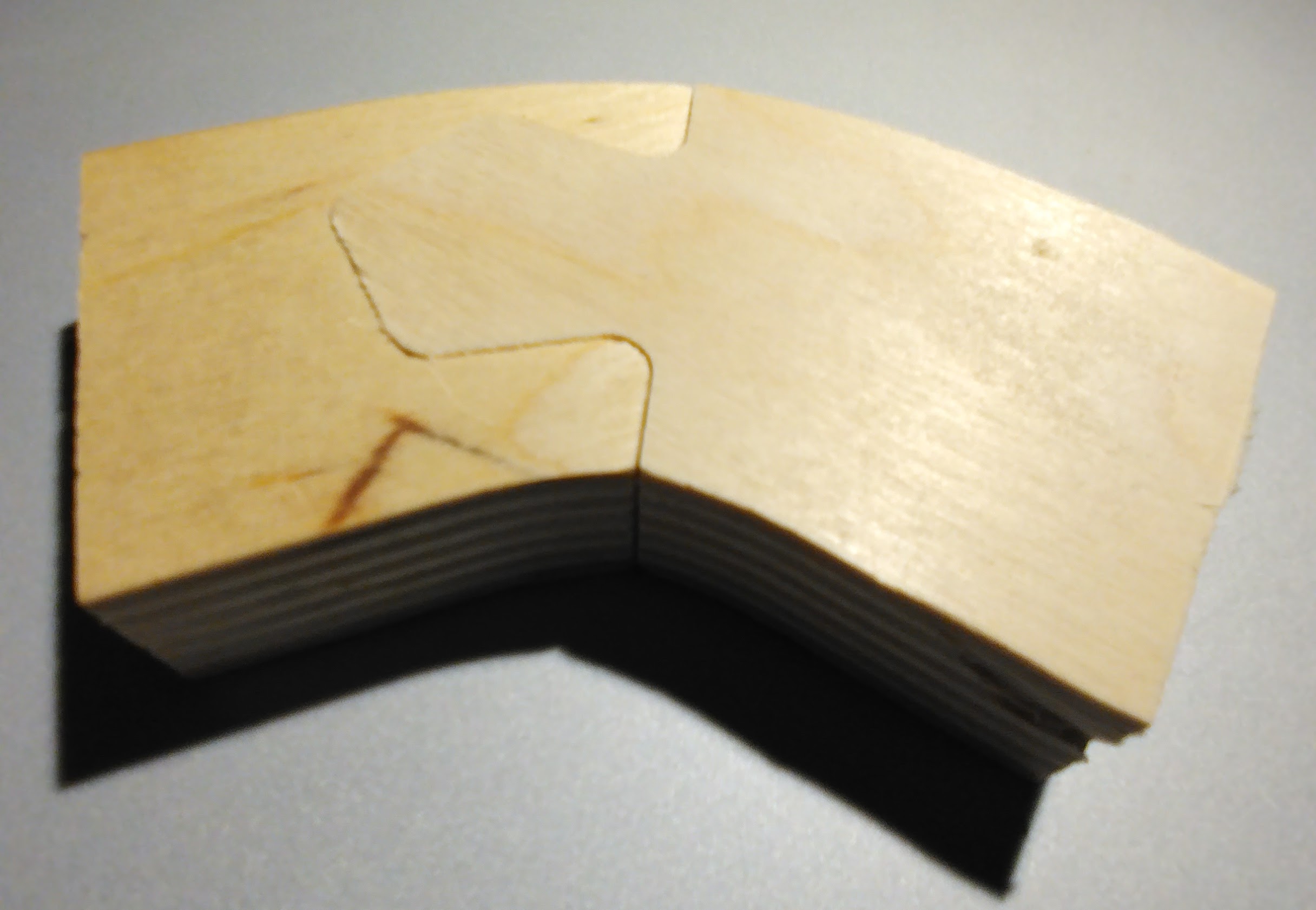
I took your file and made a few changes, but the outline of the objects is exactly as in the original (although 1 is flipped). jointtest.c2d (96 KB)
I created new toolpaths to avoid slotting. There’s a pocket for most of the depth, then a contour to leave tabs.
My (admittedly small) experience with trying to create mating edges is that it will work a bit better if you offset inwards by a small amount, say 0.1mm.
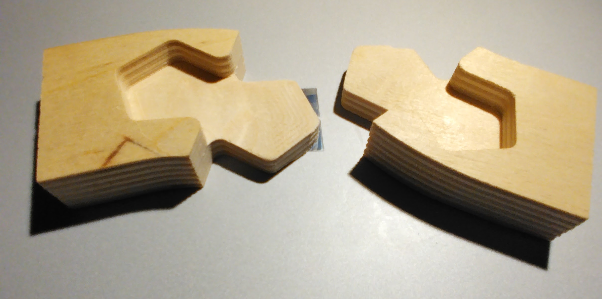
Also, some square ended mills actually have a tiny radius at the outer edge, or have worn a bit at that corner - if you don’t cut deep enough, the bottom edge will stick out very slightly, and on a tight fit it can be enough to mess things up.