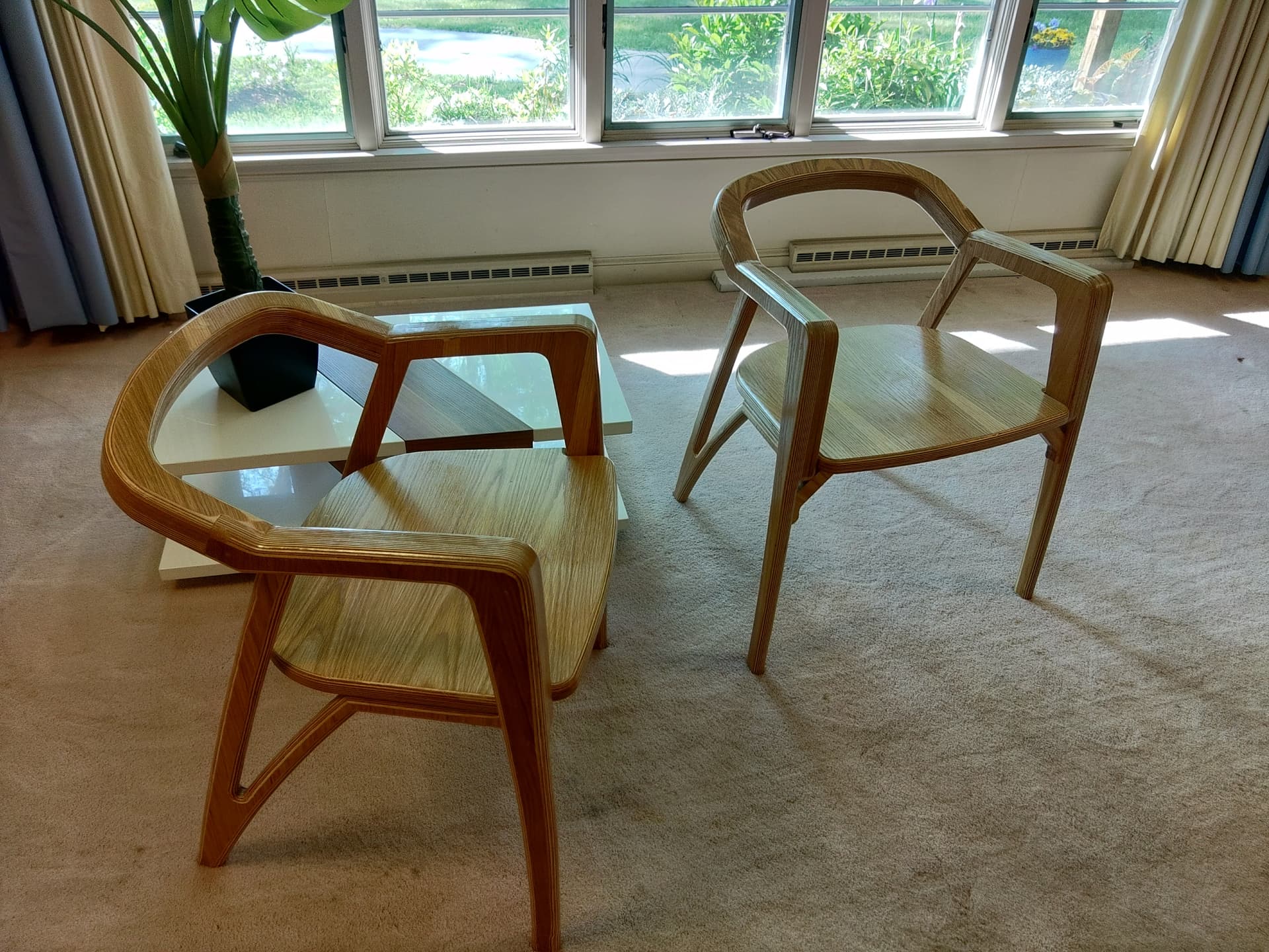
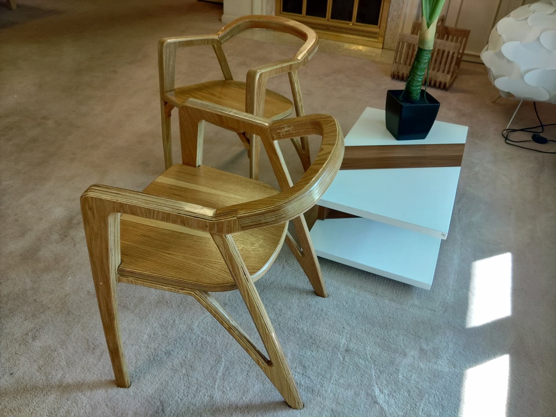
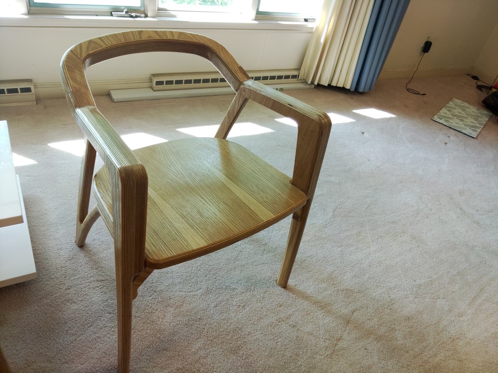
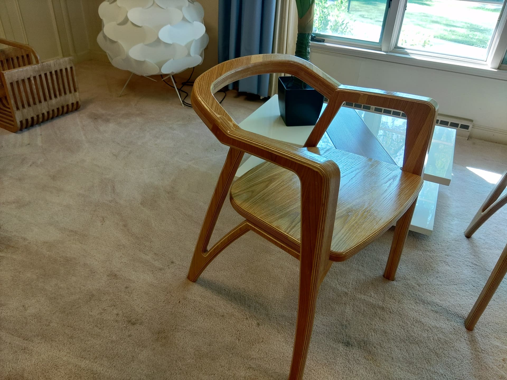
chairs finished, plans purchased from https://www.etsy.com/listing/1212279893/plywood-or-solid-wood-chair-plan-for?click_key=c4b49cf2f4a23bd0f579948c695a2d13a5348206%3A1212279893&click_sum=df781dde&ref=shop_home_active_4 , back rest needed to be redesigned, ask Abulkadir to include those, or me to send the corrected back rest files.
27 Likes


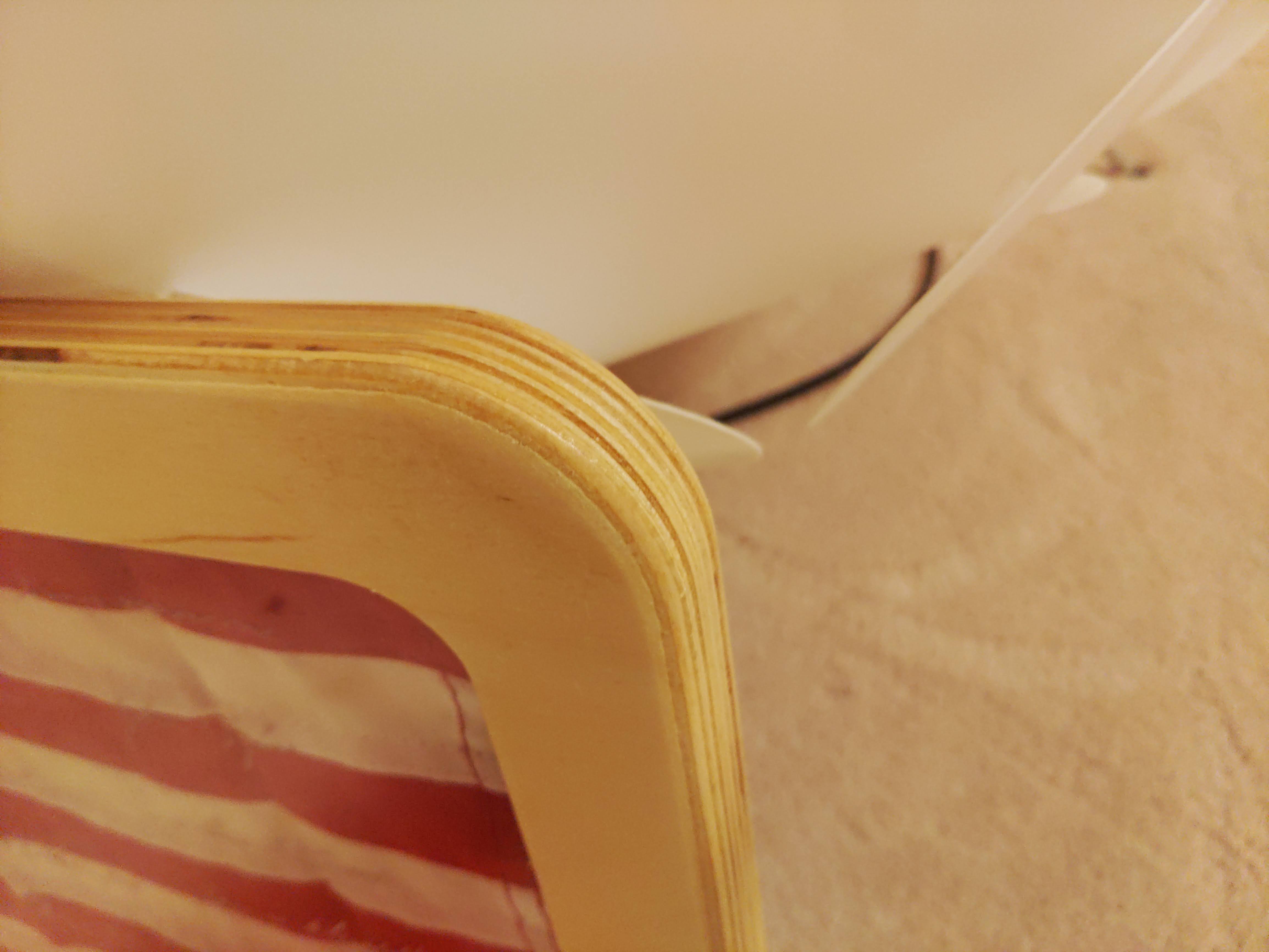
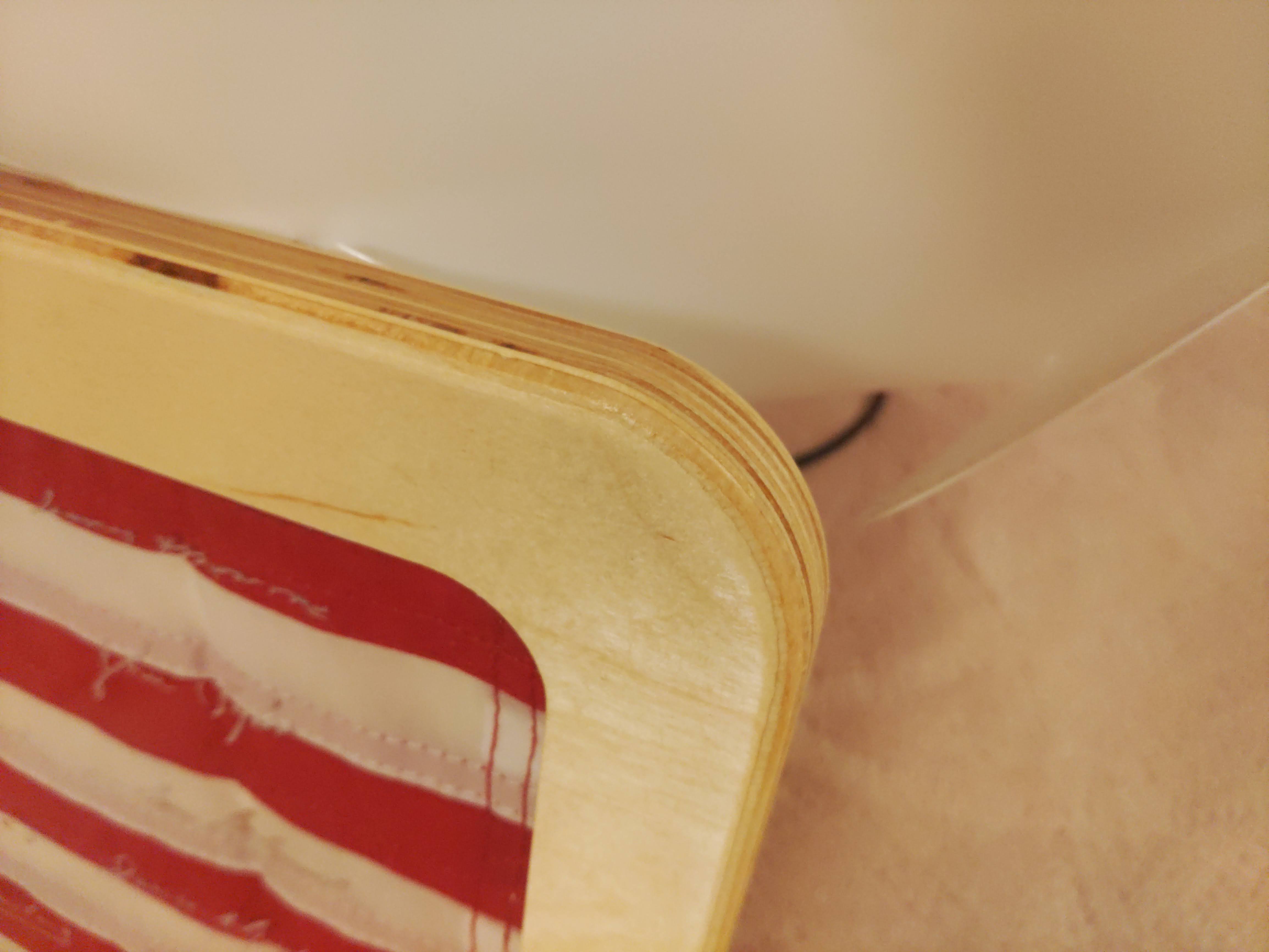
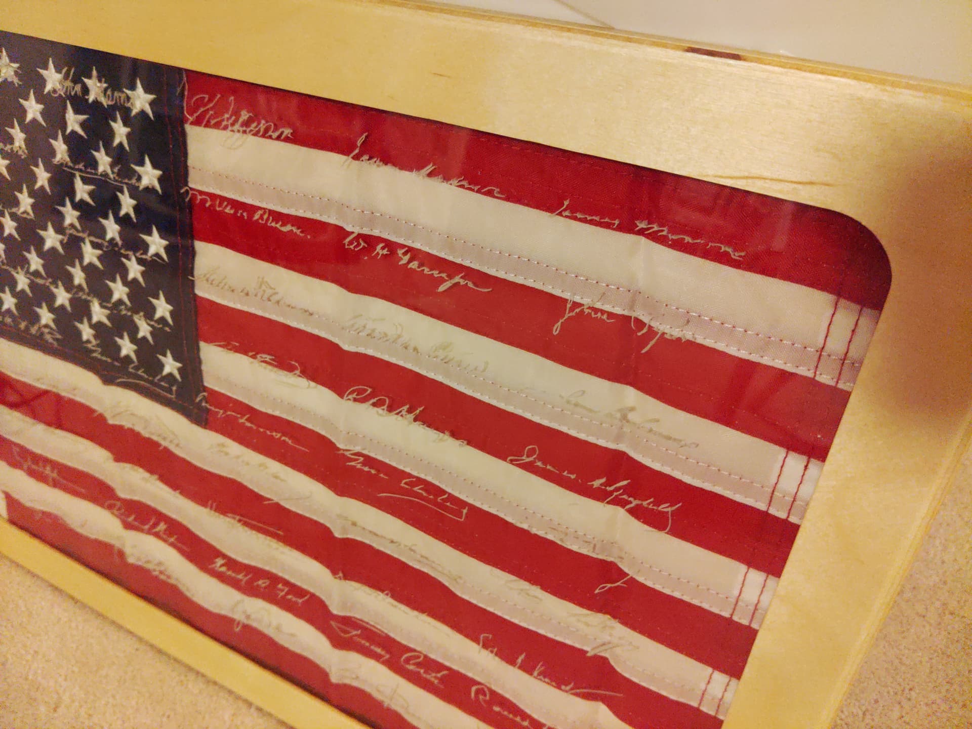
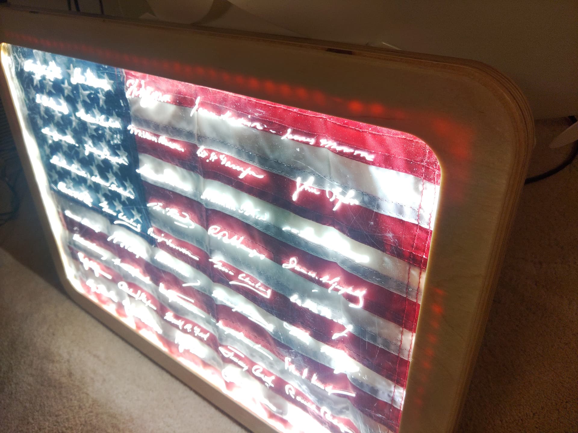
Tried out the trace function on a random internet image. (not selling this) It worked out pretty well, I think. This is .20" plywood sanded some matte black rattle can spray paint.
26 Likes
I always think Im in control too, but sometimes things just happen. For instance, the first pass of the adaptive clearing for the majority of the stock decided to go 5.6mm deep when max roughing depth was set to 1.75mm. Same thing happened on the final contour path.
In that last photo, that notch cutout is supposed to be there and was cut by hand, not the machine. The machine finished all the operations without flying anywhere. Thankfully.
2 Likes

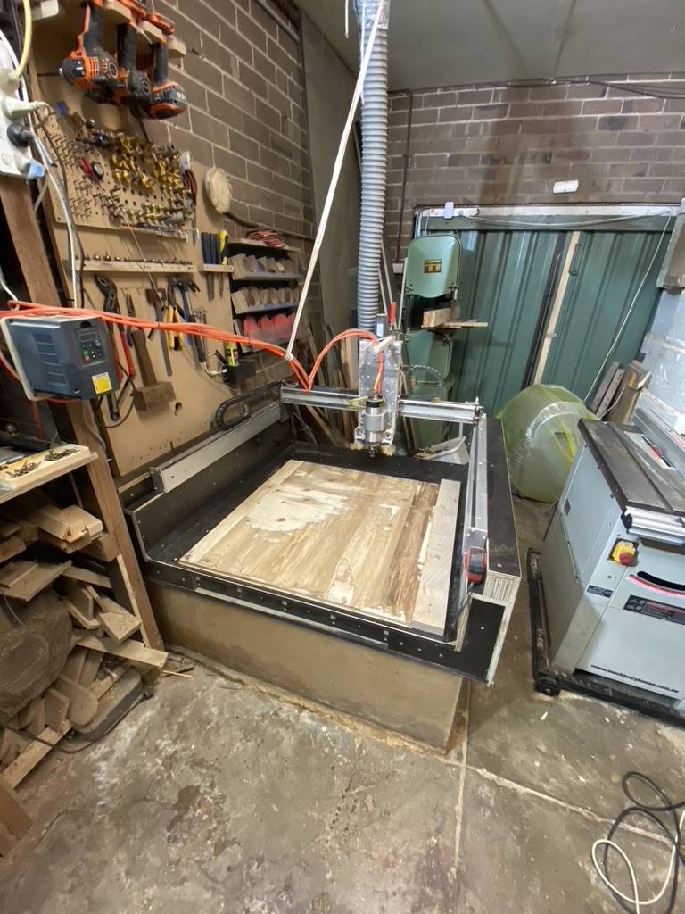
I made a new torsion box bed for my shapeoko xxl. It’s super stiff. No problem with flex or chatter. Works well! Now I have about 200mm of Z height to play with. It’s made from form-ply usually used for concreting. It’s cheap and strong.
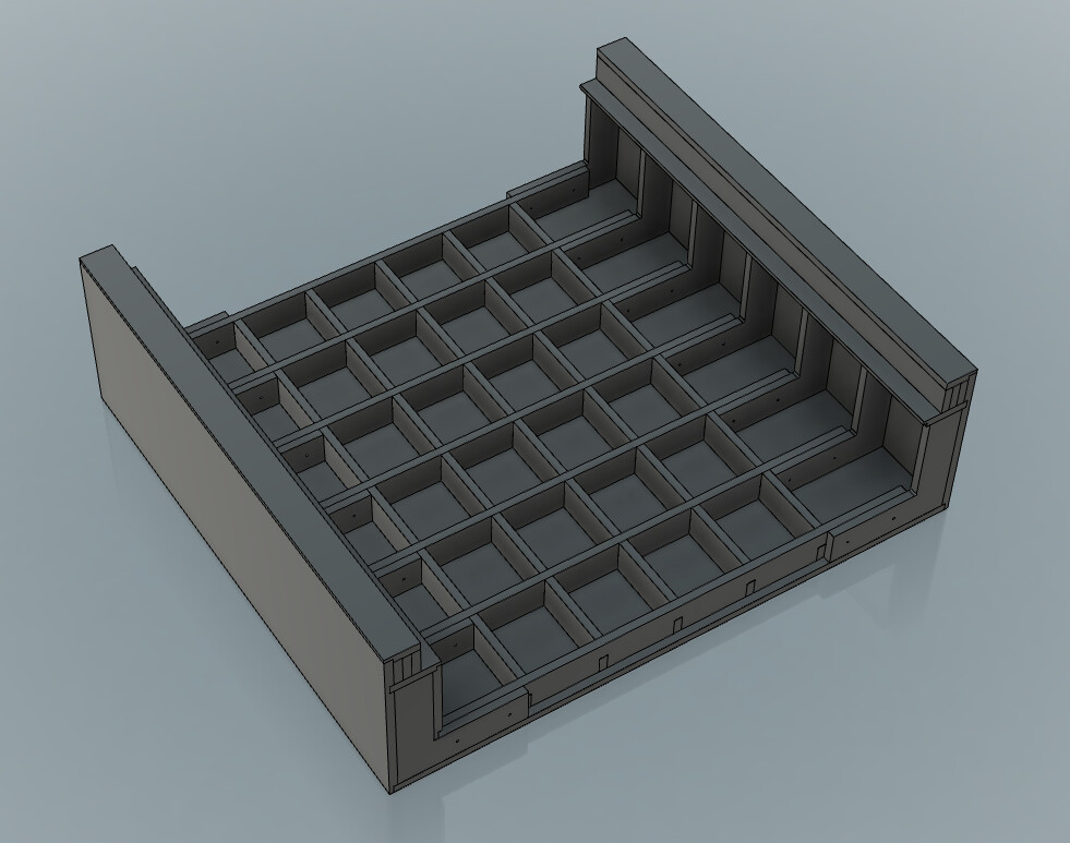
Internally it’s like this. Form-ply doesn’t glue well, so all the elements are tied together with a LOT of screws.
Previously (before they existed) I made the Z axis with ballscrew and linear guides. That worked so well, I changed the X axis to linear guides as well. Then carbide 3D made it into a product. My X and Y still use belts like the original XXL did.
The Z and X steppers were also upgraded for higher torque. It was a totally reliable production machine before the new base. Now it’s the same as before but with a much bigger Z height to play with!
9 Likes
Although that table is way plenty stiff enough to do the job of holding your Shapeoko very well, it isn’t actually a “torsion box.”
Just for informational purpose, a torsion box gets its rigidity from the glued joints between internal components and the two skins; both top and bottom. The honeycomb interior divides the box top and bottom into many smaller areas. When the box is forced to flex, either the top or bottom (with their smaller areas) has to stretch or compress; something neither is willing to do. ![]()
1 Like
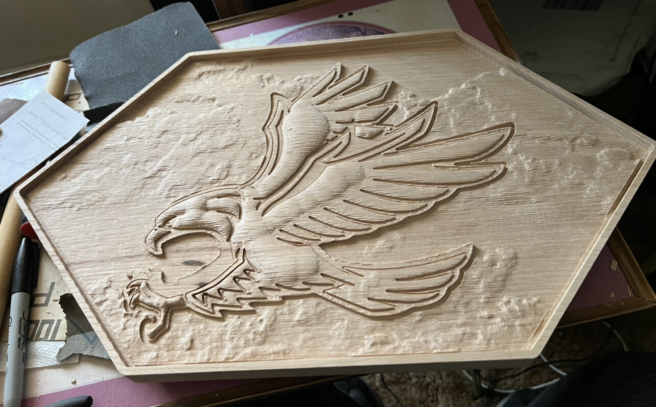
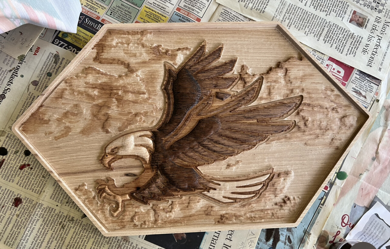
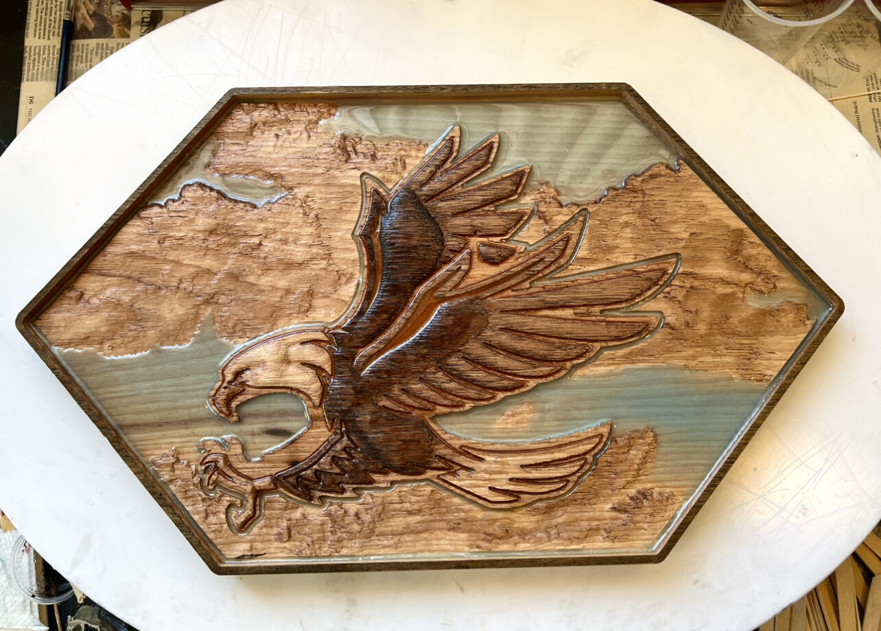
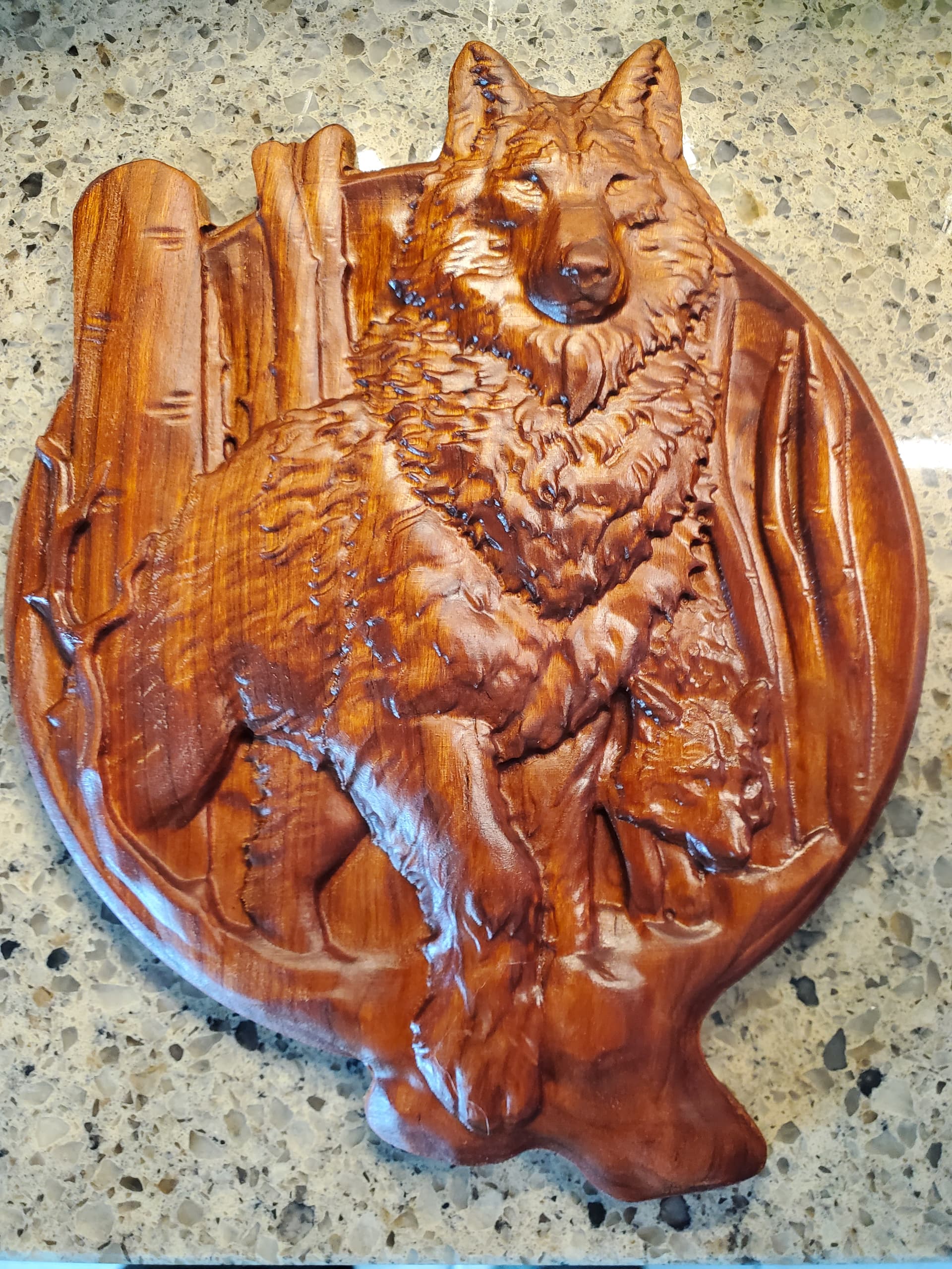
I tried an eagle on white oak that worked out. It’s not an stl or 3D file, but simply an image with which I used the round modeling feature in Pro. I used the texture option for some clouds (or land, depending on how you look at it). Did some staining with a splash of epoxy.
25 Likes
Just a simple test cut to see how well the s5 cuts sizes. I cut a 2” diameter circle and a 2x3 rectangle. Size wise they were within .001” with my Mitutoyo digital calipers. That’s close enough for me. I’m curious to see how close it is in aluminum. These cuts were just pockets, no cleanup passes.
9 Likes
I removed the top skins from the second view so you could see inside… The skins are there in the photo. (the top-most square is a machined flat spoil board. Beneath that is the top torsion box skin. The skins are not glued, because the phenolic resin surface of Formply makes that impossible. but mechanically fastened by many screws, which amounts to roughly the same thing overall. The combination of the internal parts fastened to the external skins means that any load in any direction is dissipated through the structure.
1 Like
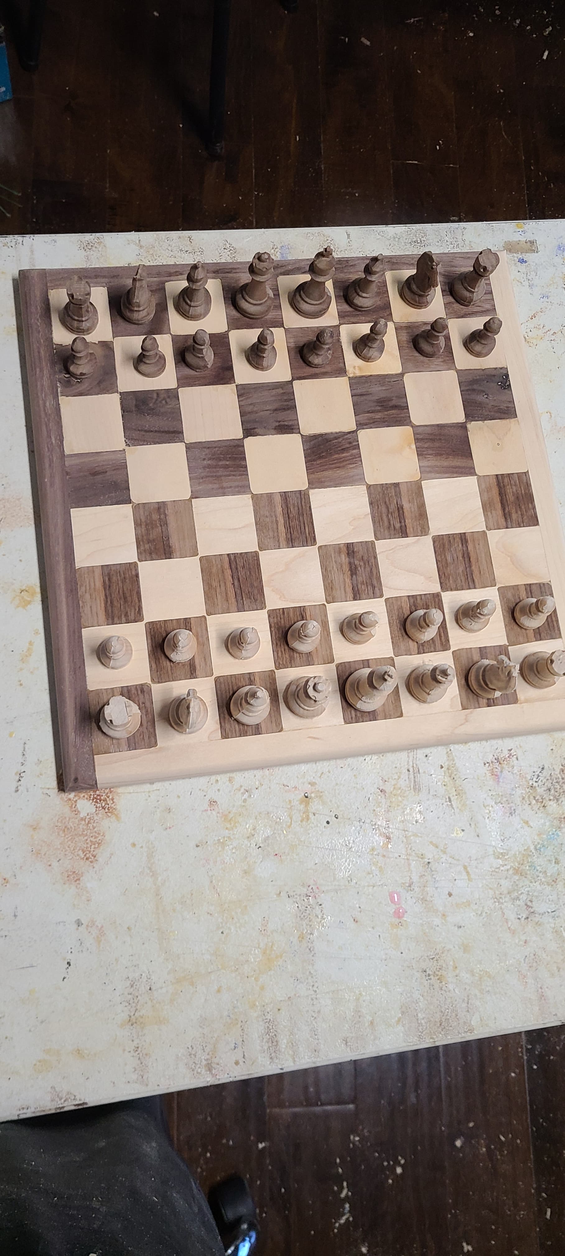
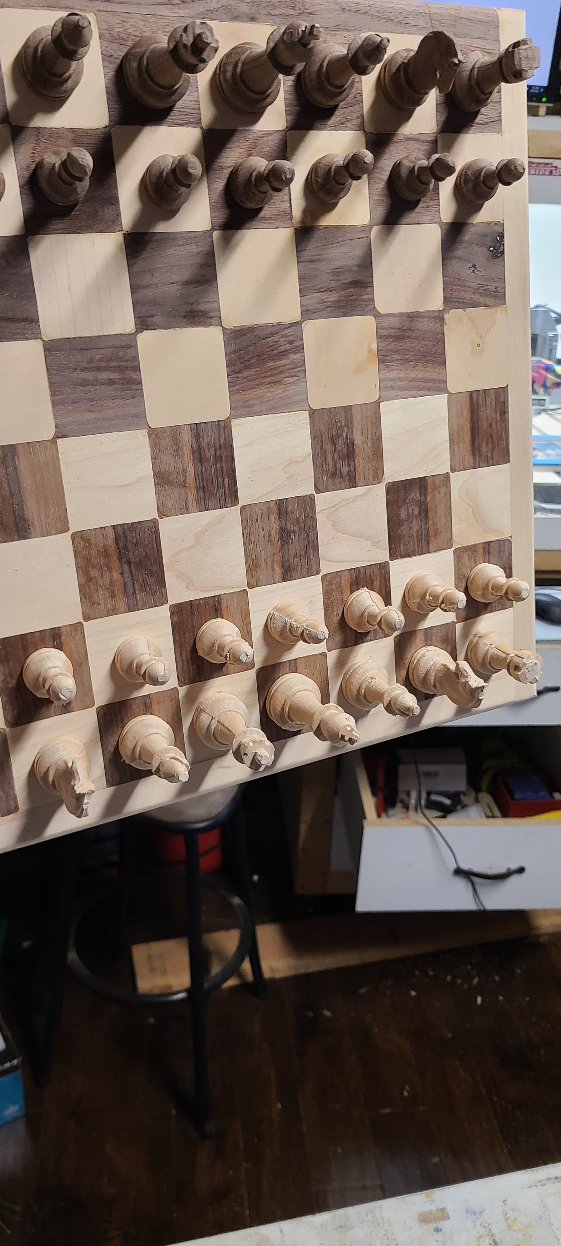
Finally got around to making the board for my chess pieces, walnut and sycamore with magnets embedded in the board and the pieces!
22 Likes
Well, I won’t see anything more beautiful on the internet tonight. I’m done.
Tell me more about this walrus oil…
1 Like
It’s a company that makes different wood finishing products. I think now they are at some Lowes locations (though I haven’t checked mine). https://walrusoil.com/
I quite like their products that I’ve gotten so far.
2 Likes
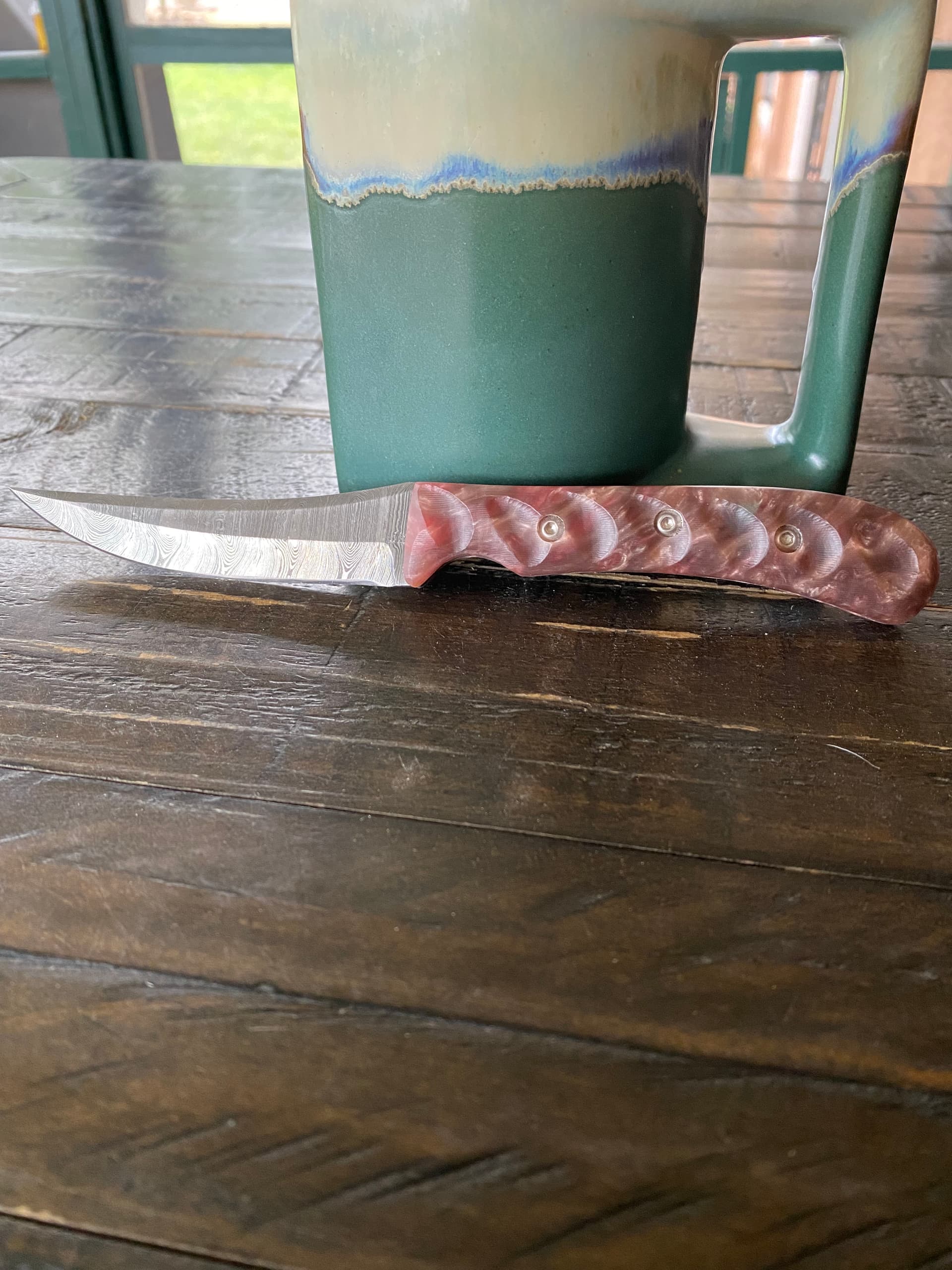
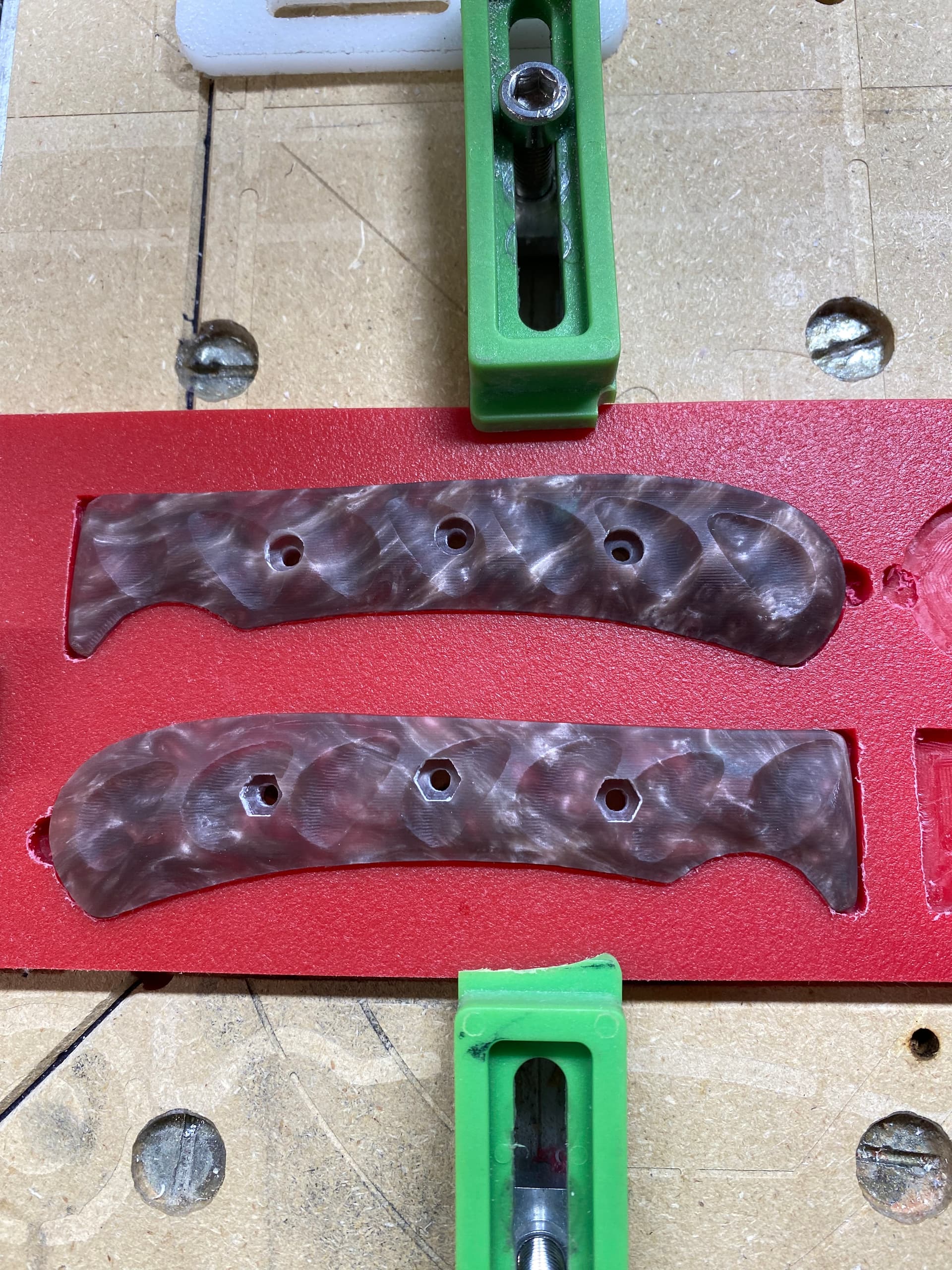
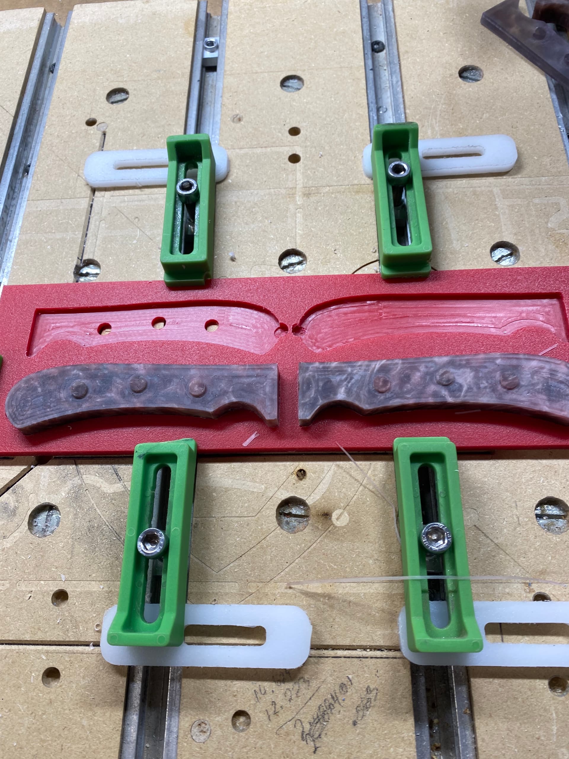
I seem to have caught the Knife Scale Bug. Trying out some epoxy knife scales, two sided machining using a holding fixture.
18 Likes
I’m still waiting for @KevBarn14 to stop by with some more insights on making cabinets on the SO5. It’s something I regularly saw on the industrial CNCs, so it’s nice to see it’s doable on the smaller ones. Once you get the dimensions down pat, you could bang out a lot, IKEA style. The latest youtube vid was fun to watch, because it was like watching myself work through iterations until I got it right.
2 Likes
Nice work. Can you tell me what depth of cut the overall project is? Is that a 2 or 3" thick wood base?
Thanks
How’d you make the pieces?
That’s the main thing that keeps kicking a chess board to the bottom of my list. Love the game, but not committing to the lathe.
It’s pretty workable to make chess pieces using 2-sided machining and a suitable flip jig — most these days are injection-molded after all.
Another crazy option, for the turned part of the pieces, would be to use your mill as a lathe.
Chuck your pieces of wood in the spindle, and clamp a tool in a vise or fixture on the table.
Then move the workpiece in the spindle to achieve the desired shape.
The blanks need to be balanced very well before spinning them at 9000+ rpms.
You need a way to chuck the workpiece in the spindle. A 1/4" threaded stud would be ideal.
You need CAM software that can program in XZ, or you would need to edit G-Code file to change Y to Z to get the proper profile. You’d also need to mirror the geometry since you’re moving the workpiece instead of the cutter. But it is possible. ![]()
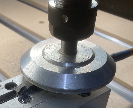
This is a much simpler example of me turning the bottom face of my sanding disc using a fly-cutter in the vise, and passing the disc over the cutter.
1 Like