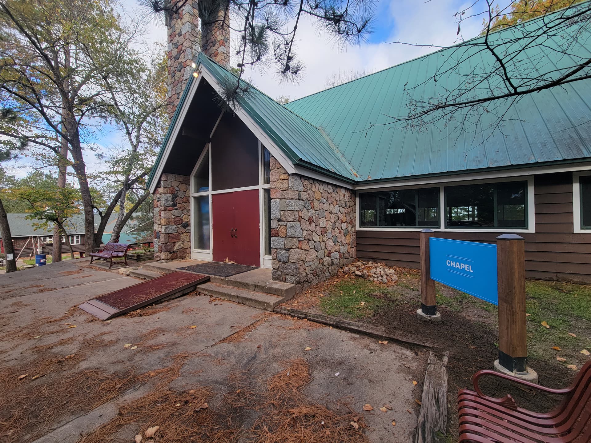
Oh yeah, and a building sign today quick.
I haven’t been posting the work stuff because it seems less fun.
Oh yeah, and a building sign today quick.
I haven’t been posting the work stuff because it seems less fun.
The acetone as a solvent in most spray pains melts most foam. But I agree in this case it helps the end result. ![]()
Possibly next time try just brushing on exterior paint first… then use the spray granite. Or just fleck on some acrylic pants to get the effect.
I love a well-made sign almost as much as a well-made tool. Is there a reason for the different colors? Did you double-side the signs? The letters look pretty deep. How do the signs stay in the post?
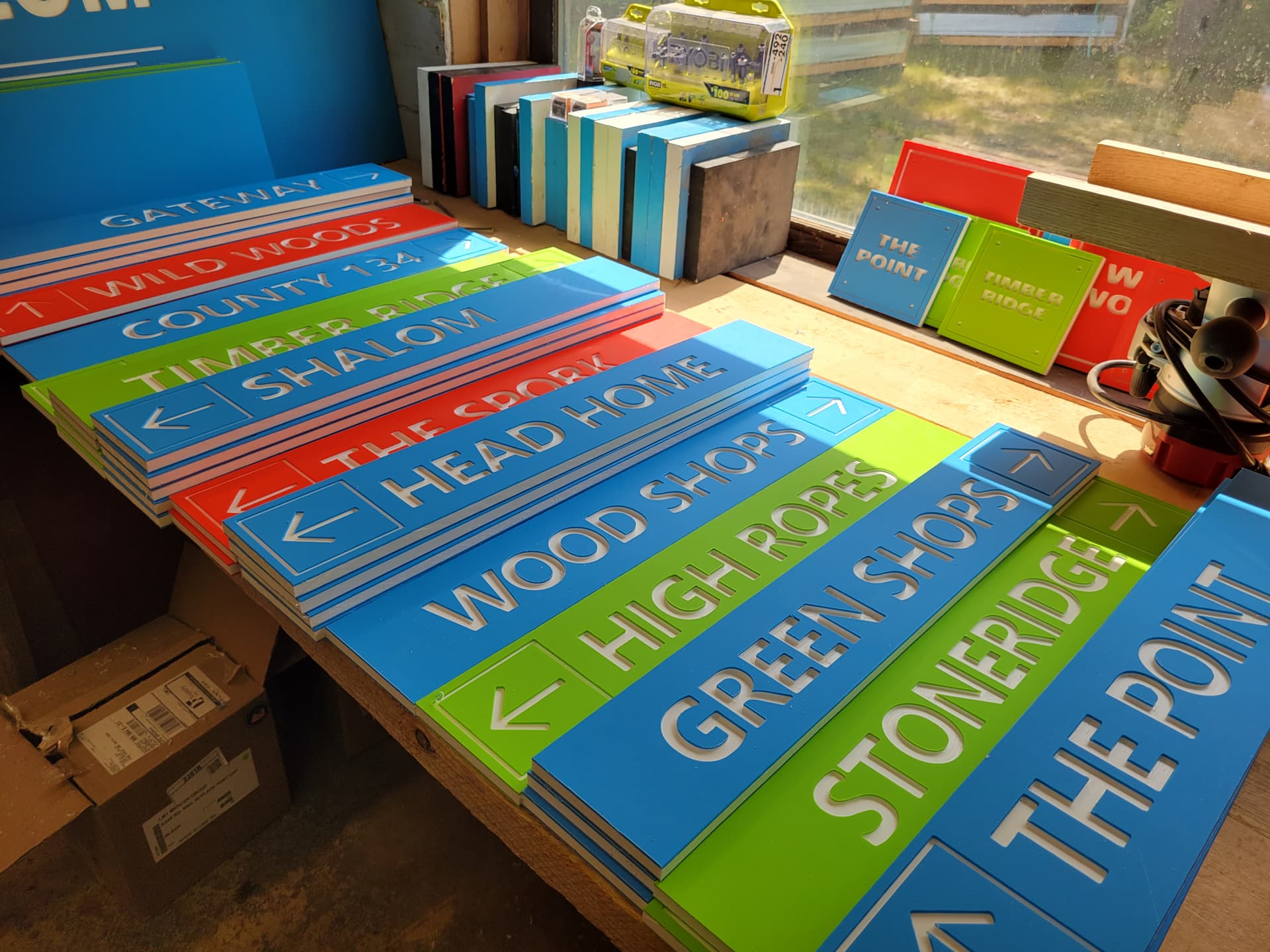
We’ve got 3 campuses. Each is color coded.
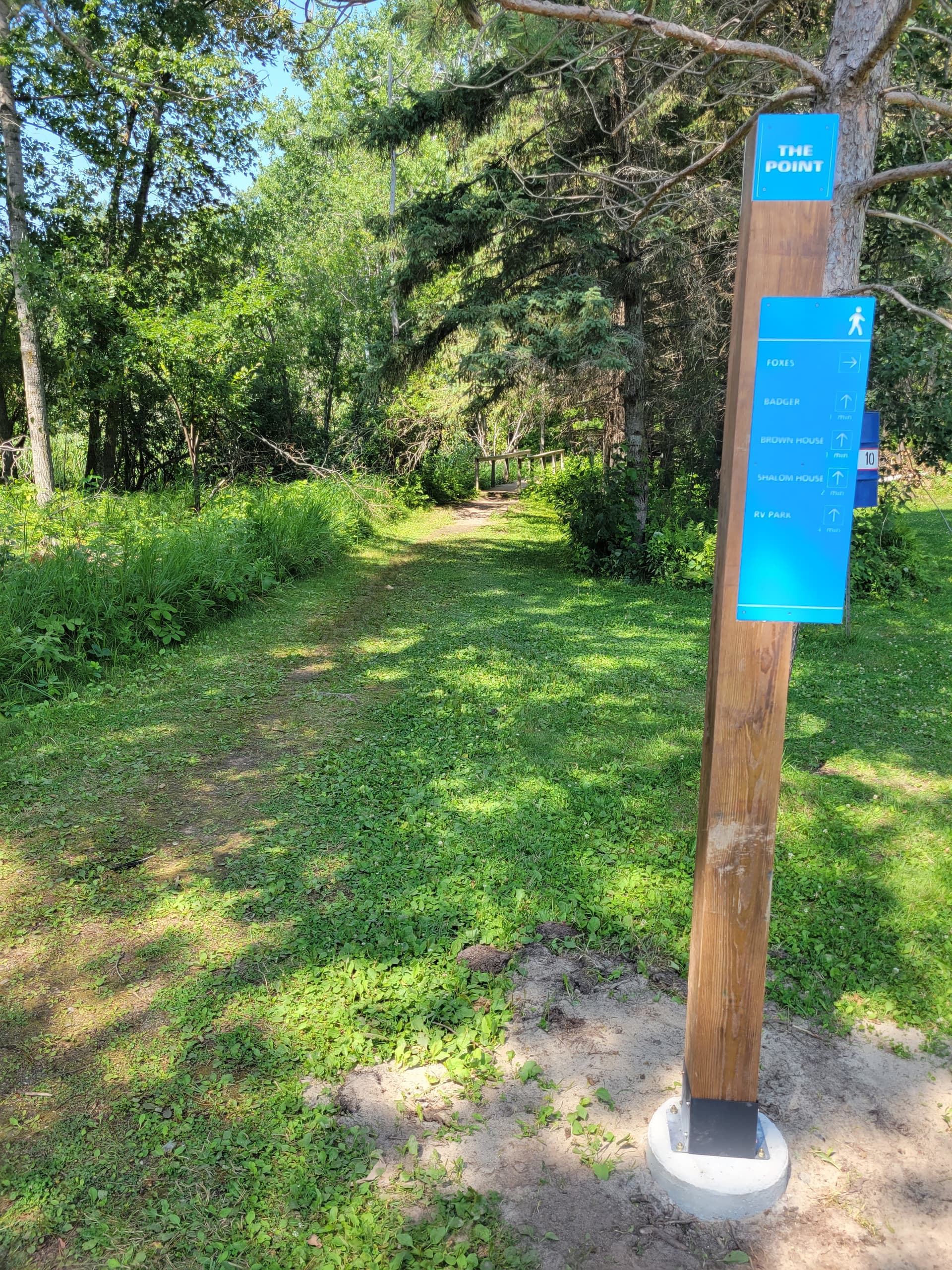
They’re instead into hand routered chanels in the post, or the front facing ones are inset. Then long deck screws through the back, through the sign.
They vetoed two sided stuff.
It’s all .15 inches. Means it always reaches the white core even if the material is a hair raised in the middle of the 2x4’ sign.
I was asked Saturday to help with a sign for the Nacgodoches Old Stone Fort. It has to go through a lot of approvals. It is associated with SFAU and the National Parks Service. I will be going over to talk to the coordinator about what they want to be incorporated in the sign. This is part of our community service for my Wood Workers of East Texas club.
I expect it to take a long time to get the design approved before I can start working on the actual sign. There are so many regulations and policies that have to be signed off on and approved. The SFASU is not part of the University of Texas system and the Physical Plant Services has the authority over the signs. The SFASU has a standard of purple posts and white signage. So all of those details have to be worked out go through committee after committee. In the end I may be sorry to have volunteered for this. Plus on top of all of that the National Parks Service also some part in this.
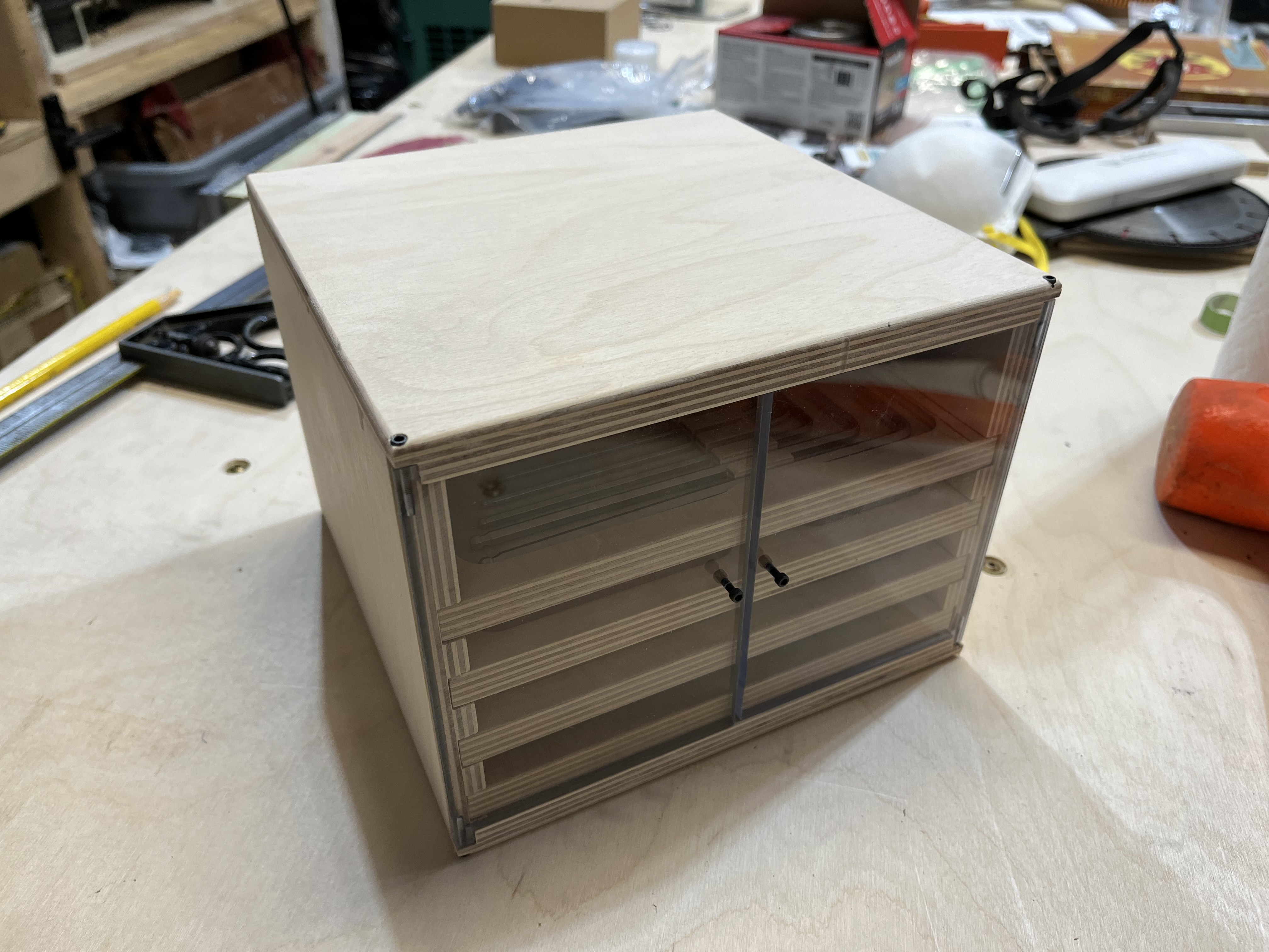
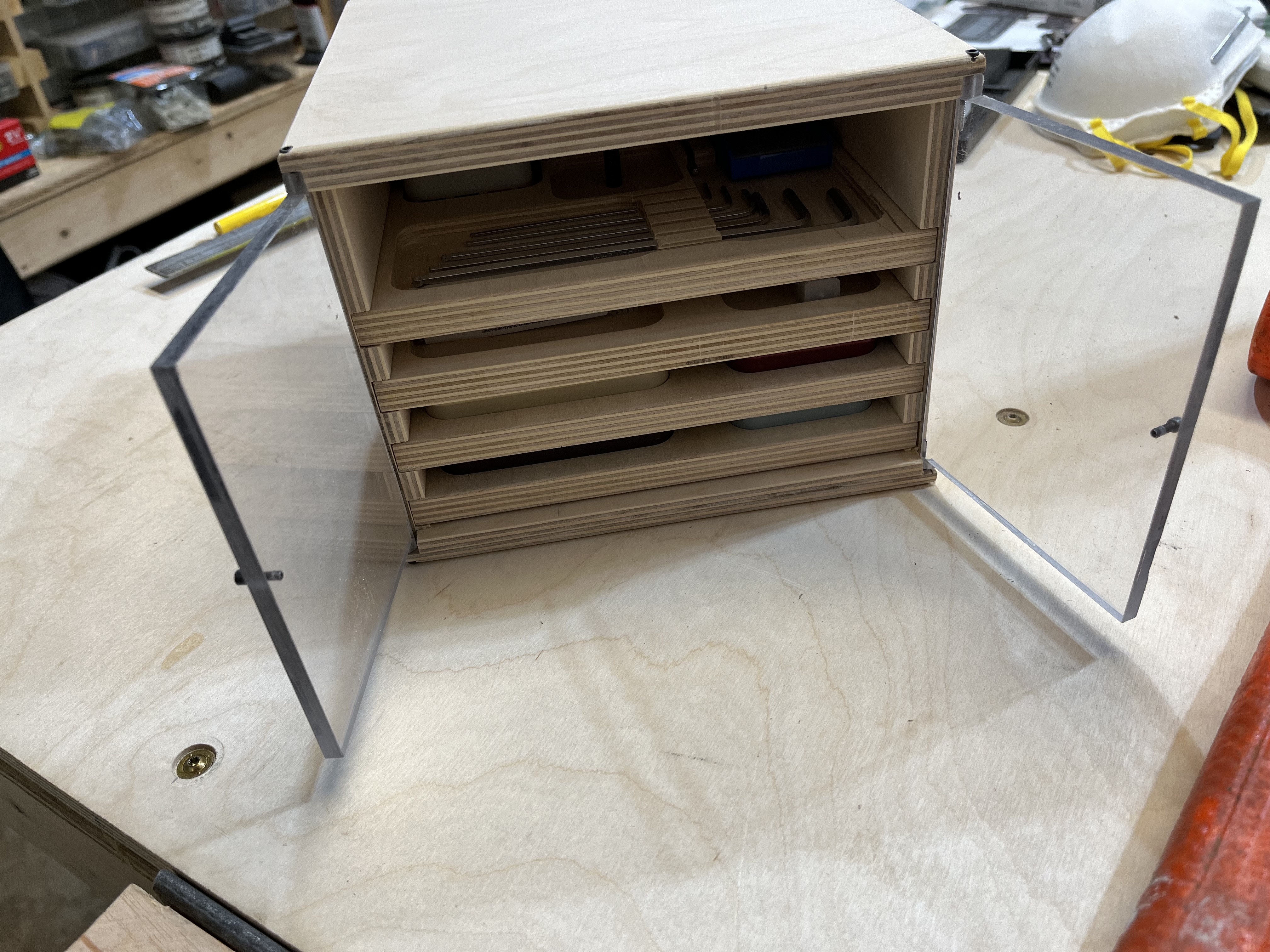
I ordered a whole bunch of cutters right after getting my Pro XXL and they came packaged in these neat little tins from Carbide. I really liked the tins but wanted a good storage container for all my cutters and setup tools in one place. Until now, that place has been my workbench (not ideal).
I wanted a little cabinet but designed it to accommodate the little cutter tins from Carbide so I could have them still part of my collection. I decided to make a little box with trays that slide in and out so I can take the trays out and bring them to the machine as needed. I also
Run the machine with a mini PC so I made the box just the right size for the PC to sit comfortably on top of it.
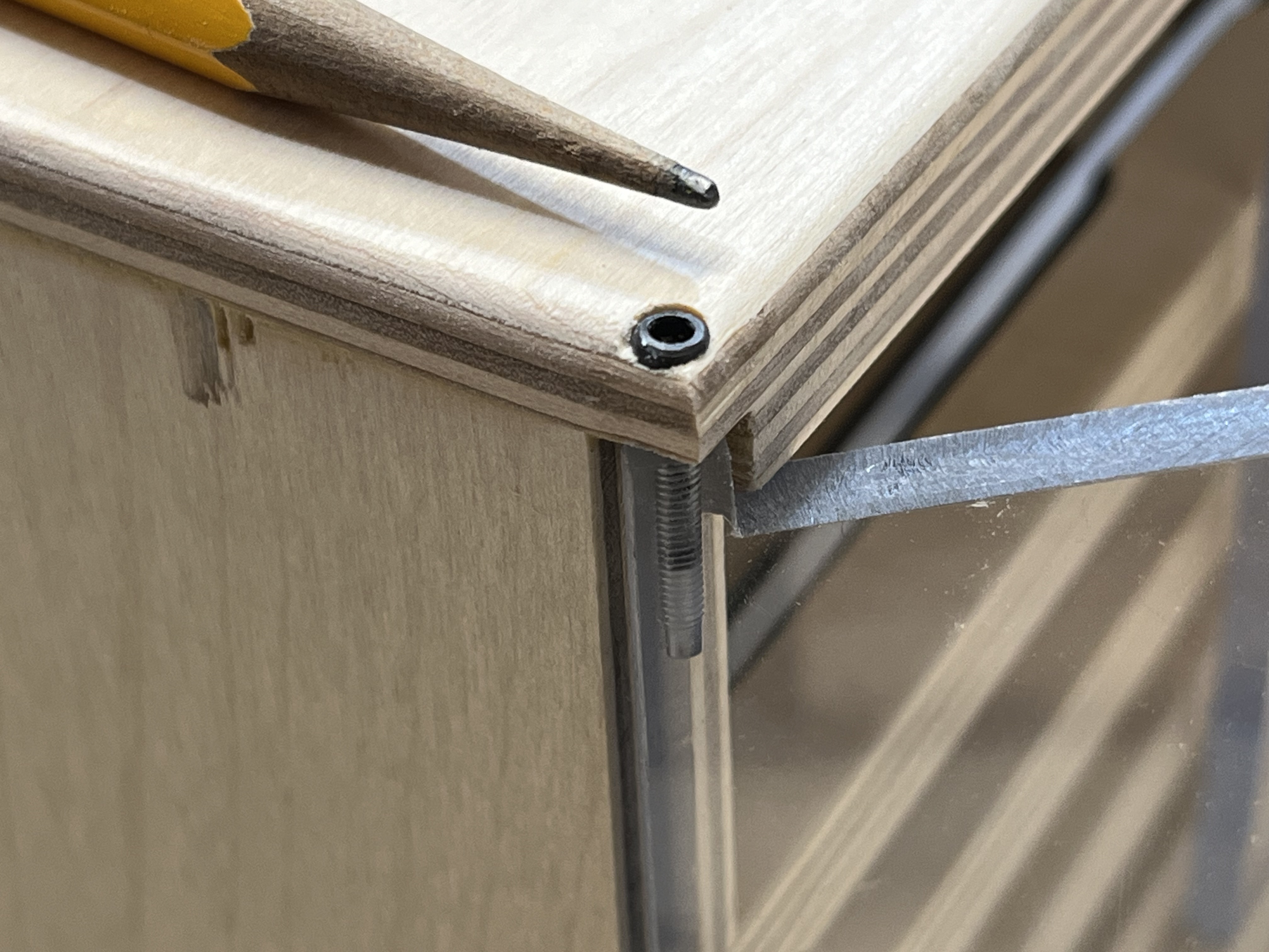
I used 12mm Baltic birch for the body and trays, mostly the .25” cutter that came with the machine but also the 1/8” and 1/16” for some of the little pockets that hold the hex keys in place. I used default feeds and speeds for soft wood and hard plastic (doors). I did the round over after the box was all glued up using my router table. I find some things are easier off the CNC but then pocketing was great on the shapeoko. I drilled the door hinge holes and counterbores by hand with the doors taped in place. I didn’t have a 3-48 tap so I got out the old rotary tool and cut a couple grooves in a spare screw…not I have a great little hex drive 3-48 tap good enough for plastic anyway.
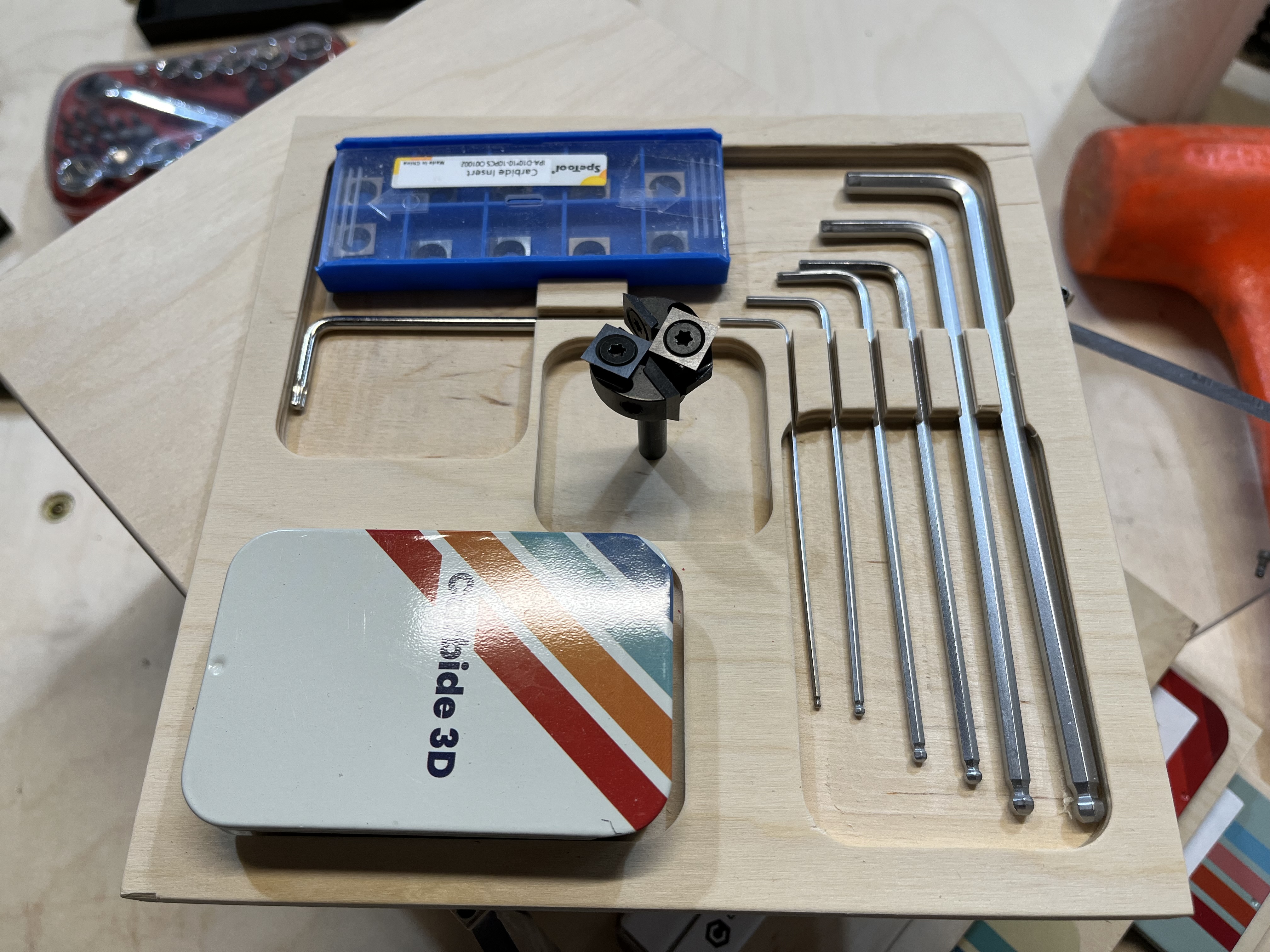
I cut the tin pockets a little too tight at first, but was able to do a quick recovery before pulling the part from the table by running a new pass. I drew an offset pocket 0.005” larger in all directions, then made an extra tool path as a contour (keeping inside) so it did just a clean-up or rest pass, only costing me a few extra minutes. It worked great.
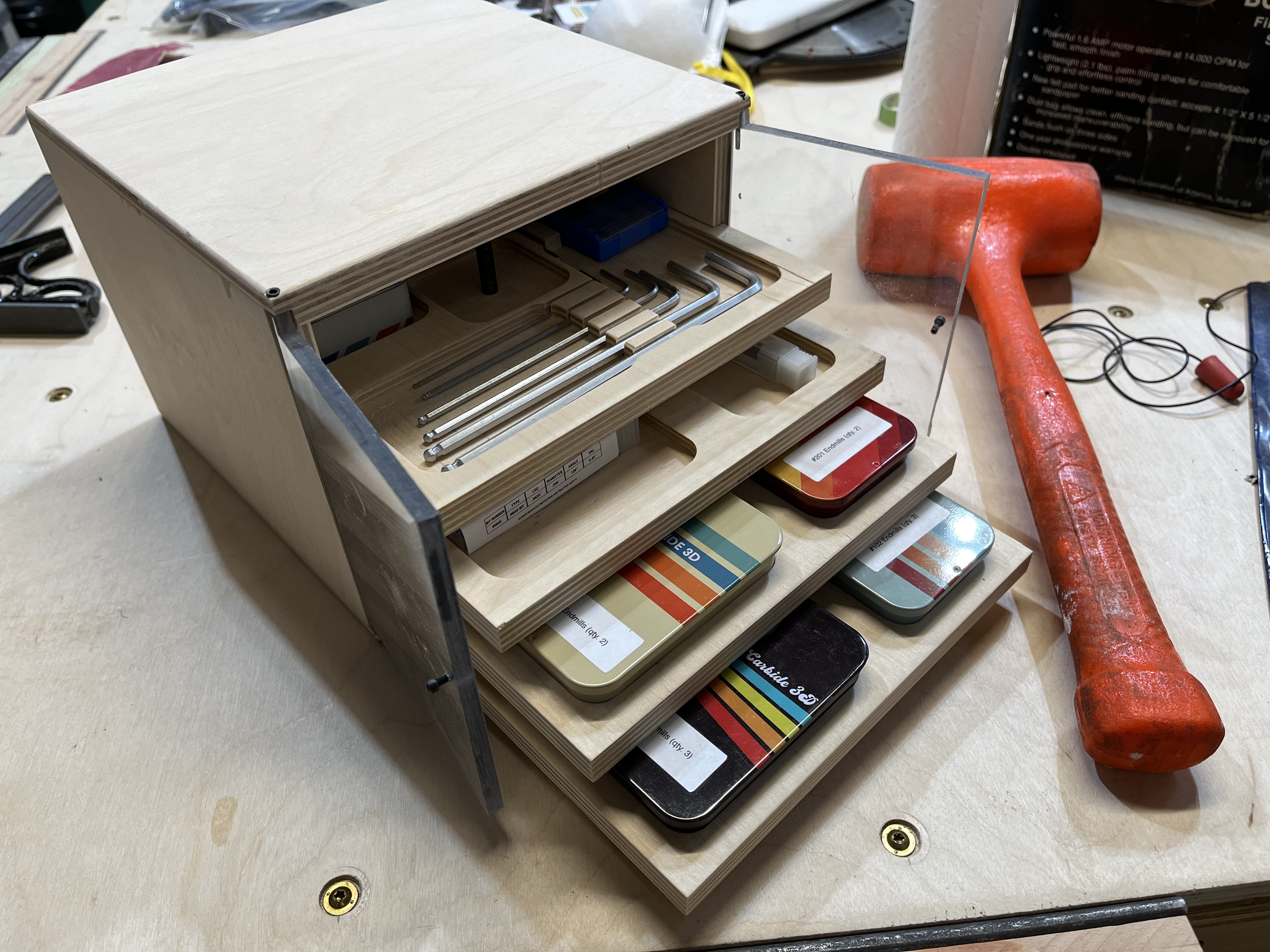
Here are some pictures of the finished (except finish) “toolbox”.
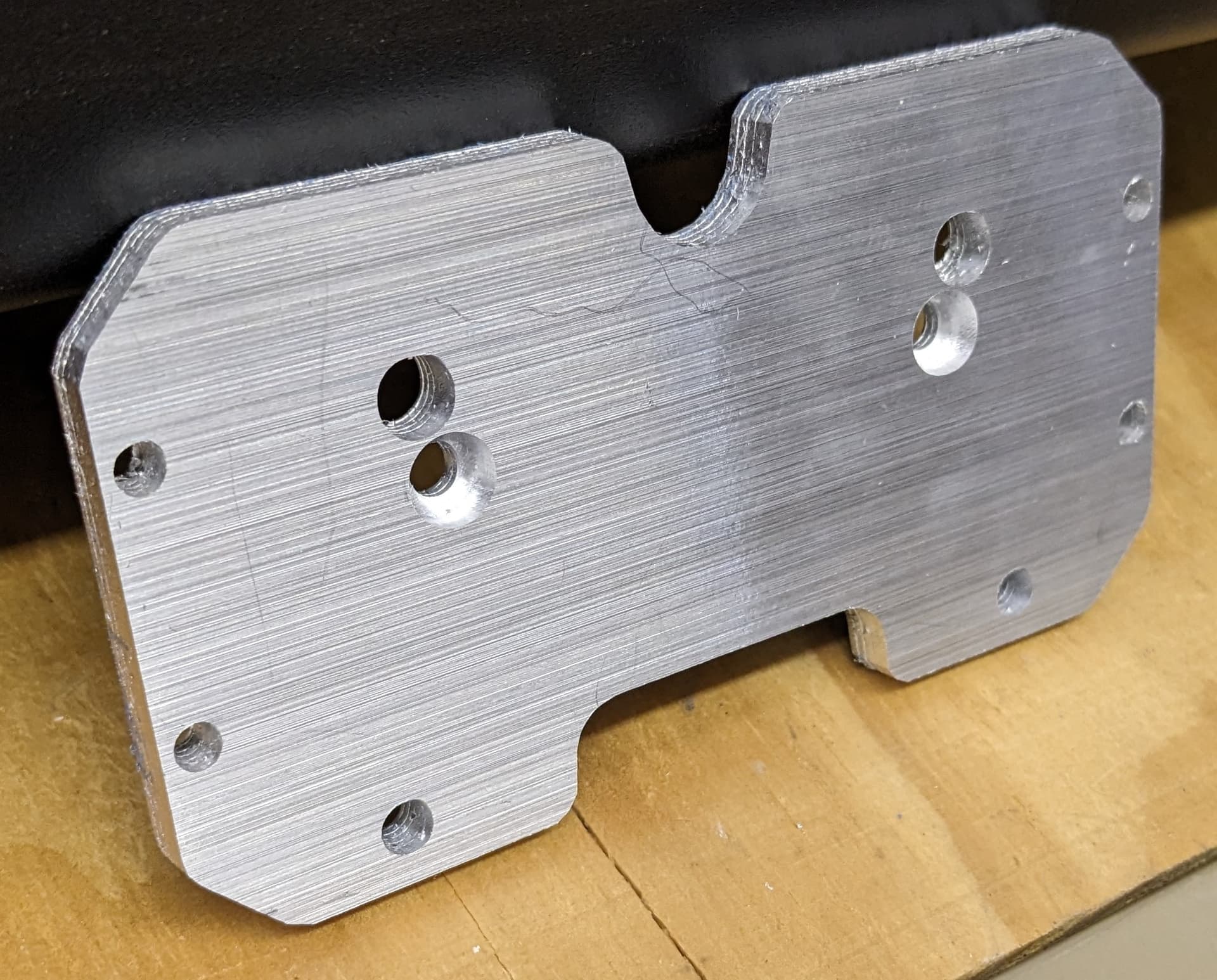
I finally got around to cutting the “DIY EZ Tram” to lower the Z-Plus travel on my Shapeoko 3 XL. It’s fresh off the machine in the photo - needs deburring. This part used to be posted on CutRocket but I see that it’s been removed. I saved the file some time ago. I wonder if anyone else has tried this?
Clever idea for the allen wrench holder. Mine just get thrown in a box with clamps, etc. lol
Thanks, that was actually the original plan, but when I realized I would have to merge two of the pockets I sized for the tins I figured I would fancy it up a bit ![]()
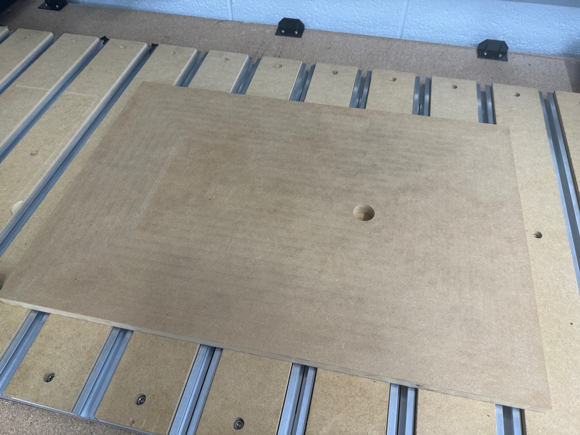
I’m still on my newbie cnc journey so excuse the lame picture/post but I finished the setup of the workbench for my Shapeoko 5. I added some acrylic “shields” around the outside of the machine to keep some material in but more so to keep metal bits from flying into the machine from the nearby workshop.
After that was done I wanted to try out the McFly cutter I just got and tram the spindle after. First I wanted to take 1mm off of some MDF for a smooth surface to square everything up to. I thought I set everything up correctly and excitedly watched that big surfacing cutter slowly move over the material for the start of the path and then angrily dive down through the entire depth of the material is an instant. I barely got the “oh shit” out of my mouth before it was at the bottom and I smacked the e-stop.
I went back to my file although I couldn’t spot my mistake, I just restarted the process in Carbide Create and zeroing and the second time was successful in my surfacing.
For tramming I used a 3d printed arm and two 1/4" flat end end mills (one in machine and one at end of arm), in hindsight I probably should have used some precision dowels.
https://www.printables.com/model/66757-tram-arm-for-cnc-router
The 3d printed arm worked great and I was quickly able to determine that I needed to add a bit of shim to the bottom of the spindle. I cut and folded some aluminum foil until I got that dialed in.
The left right alignment was the bigger pain in the butt. I probably loosened the bolts 20 times because I kept going too far one way or the other as I tried to align it without a solid reference. I watched Winston Moy’s Carbid3D tramming video AFTER finishing and realized I could have saved a lot of time utilizing 123 blocks.
I eventually got it done though and did some pockets afterwards with a noticeable improvement.
I can’t figure out what material you are using here (and where you got it)?
Doesn’t look like King Colorcore (which I use). Is this some kind of foam?
John
Excellent signs, Mark!
I really like the colors, I bet they show up great in all weather.
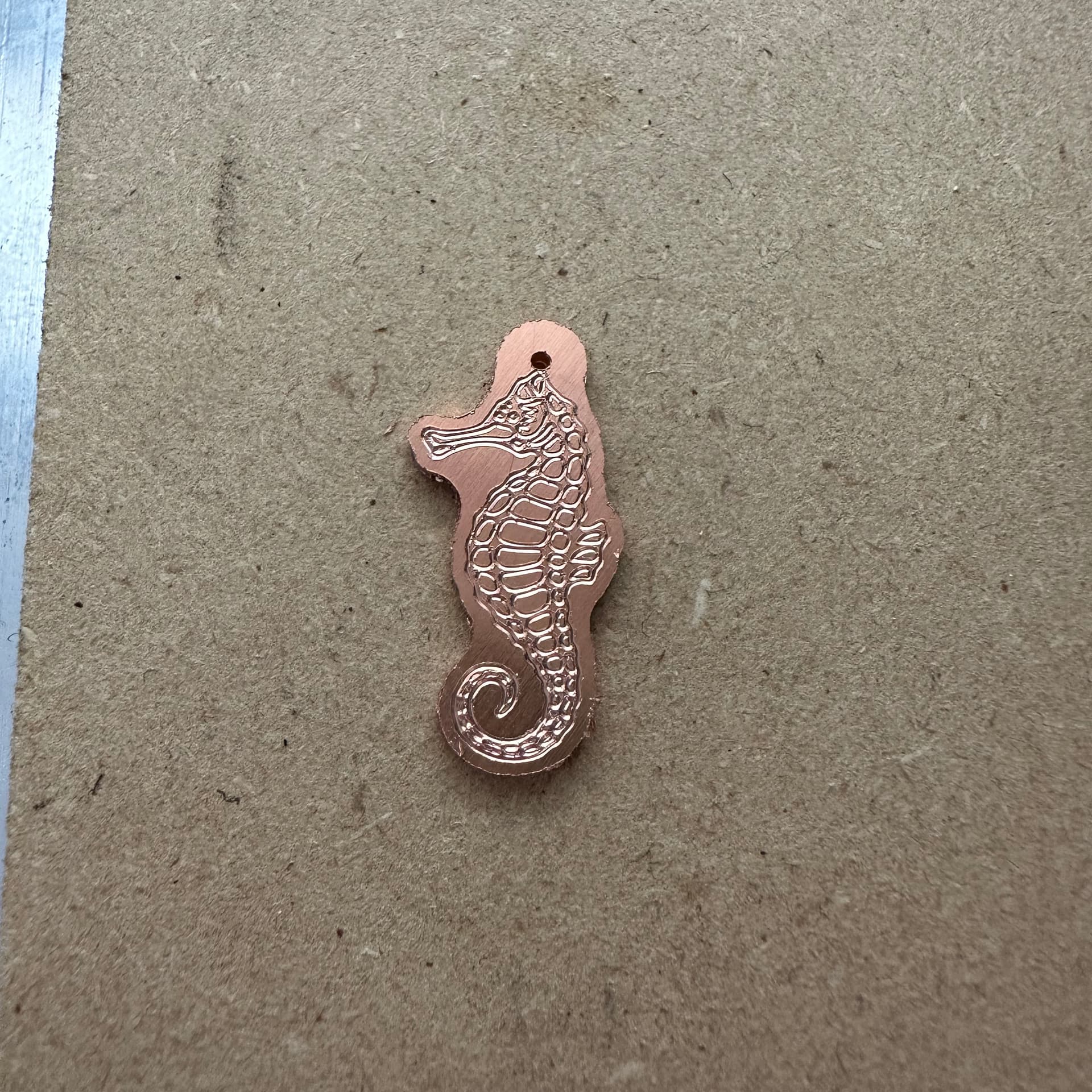
Here’s a seahorse pendant I made using a line drawing I found online. It’s about 7/8" tall.
Trying many copper earring designs this past week, it was tremendously helpful to leave 0.005" of copper around the outside of the earring until I was on my last toolpath. If I cut all the way through with a #102Z from the start, then tried to hit the details with a #112Z, the tiny earrings wouldn’t stay on the blue tape.
I’m looking forward to winter here. They’re gonna glow in a world that’s all white.
Pretty sure it’s HDPE. If it’s not that exact product it’s really close. I didn’t source it though.
I’ve made some things with HDU, which is great. It doesn’t hold up to life around kids though.
I do quite a bit of these fish ornaments for my Bass fishing buddies using 5" x 7" x .025" anodized aluminum. These are two sided engravings with the 120º McEtcher. I’ll engrave one side, flip horizontally engrave side two, then a peck drilling toolpath for the holes followed by a contour tool path with the 112Z for cutting them loose. Tape and CA glue hold the aluminum in a piece of MDF pocketed out to the size of the work piece. These are roughly 2" x 1.25".
Usually if the bit does an unexpected dive like that, it’s because you changed the bit during the jog menu. I too have found out the hard way, do not change bits unless CM knows you are doing it.
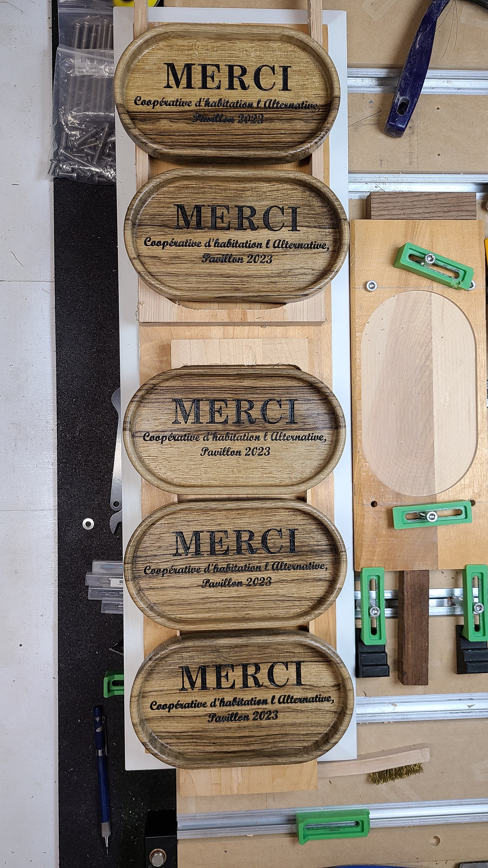
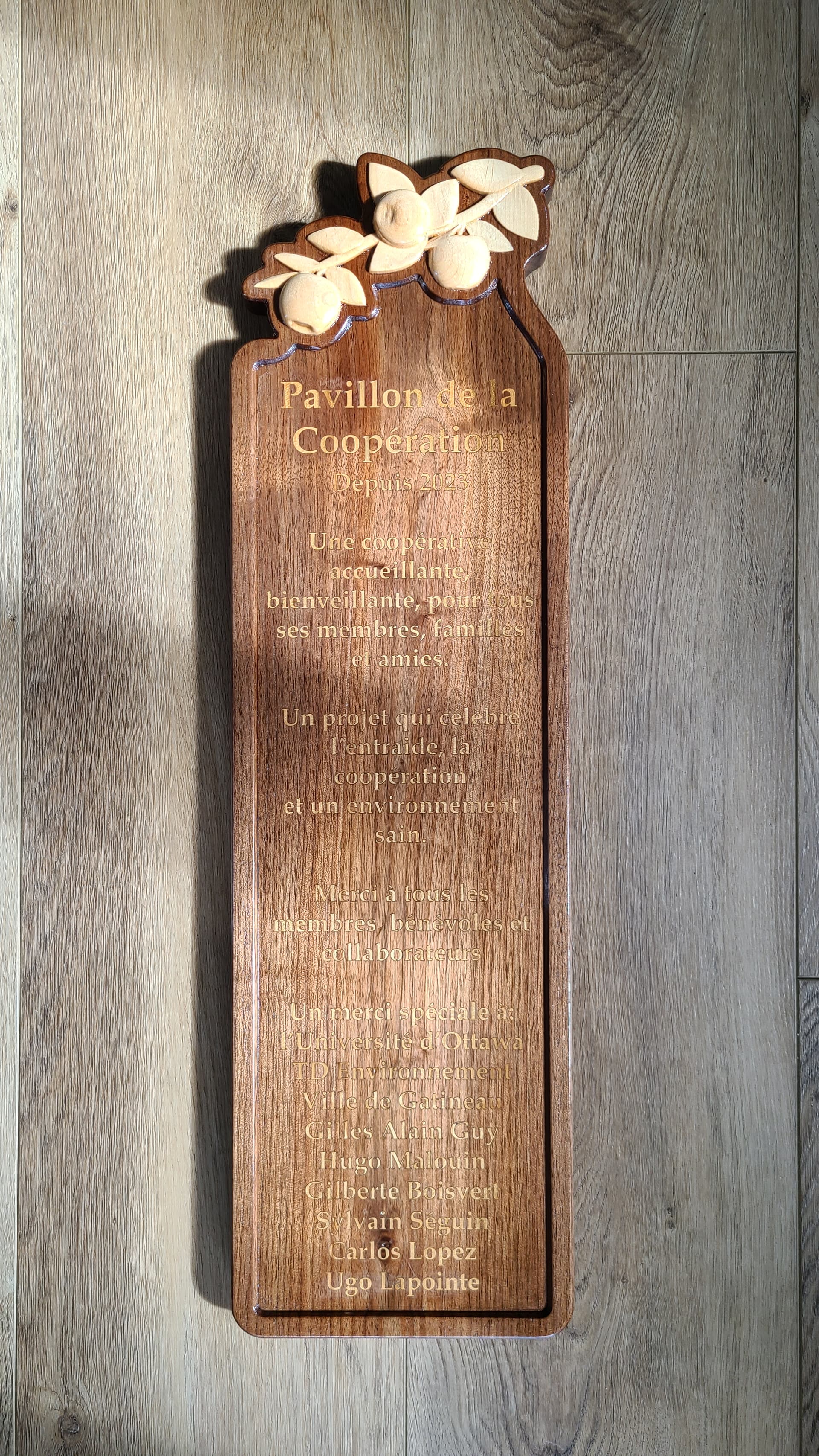
Made some small catch all trays that the client wants to give to some of the volunteers that went above and beyond in the construction of a community structure/pergola. These will complement the sign that will be installed on a pillar of the structure which was done earlier this week but now i got three coats of spar varnish on and the wood grain is a live. Another one done… time to start something else.