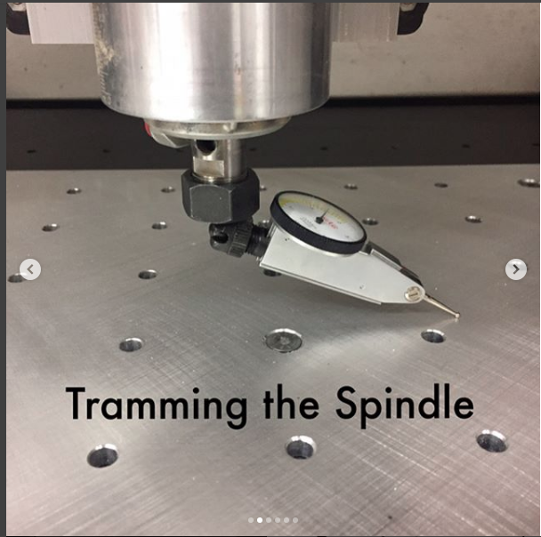
Many revolve around the idea (pun intended) of mounting a dial gauge off center from the spindle and rotating it to see if the height it measures varies. If the mount is clamped in the spindle collet then you don’t need to worry about calibrating and levelling the dial gauge mount as whatever error it has rotates with it.
There’s shiny aluminium ones from tool stores and Amazon, other folks use a bit of wood. There are even nice collet mounting dial gauge holders which you can use for center finding and other tricks too.
There’s some pics of a nice one in this thread;
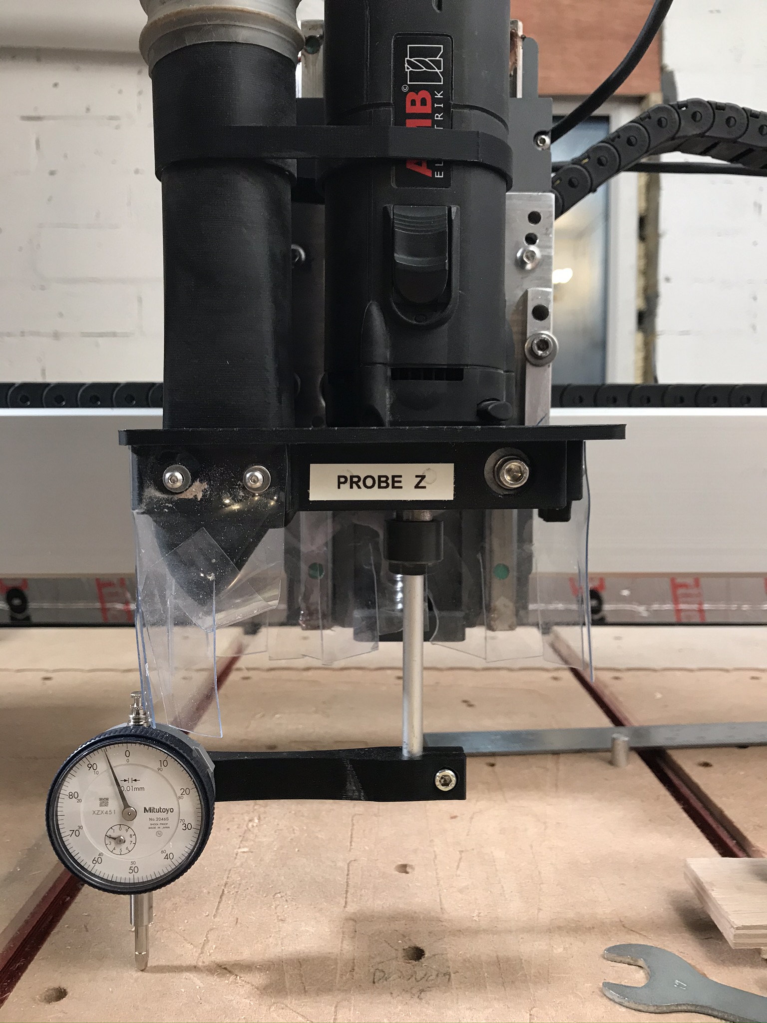
Here is my bit of 8mm aluminium round bar (you can use 1/4" too) with a bit of 3D printed plastic to hold the cutter (it would be easy to use wood in place of the plastic)
I step the Z axis down until I get about 0 on the dial, then rotate the spindle by hand - unplug it first and do not allow it to power up. I watch to see if the dial goes up or down as I sweep from left to right, that’s the side to side tram, then check front to back and that’s the front to rear tram.
It might be necessary to level the spoilboard first, tram and take a final skim once you’re level.
I prefer analogue to digital and I understand the need for the off-set, but was looking for a solution with a guaranteed pair of opposing right angles and with a mount for the dial. The ones I looked at on Amazon seem to be really complicated affairs with knobs and threads all over the place! I much prefer simple!
I’m not telling you what to do, but I almost never buy a single use tool. This is my spindle tramming setup, and when I’m done, I use the indicator on the magnetic base that came with it to make precise set up on my machine when needed. It’s also a lot less money. 2B1S
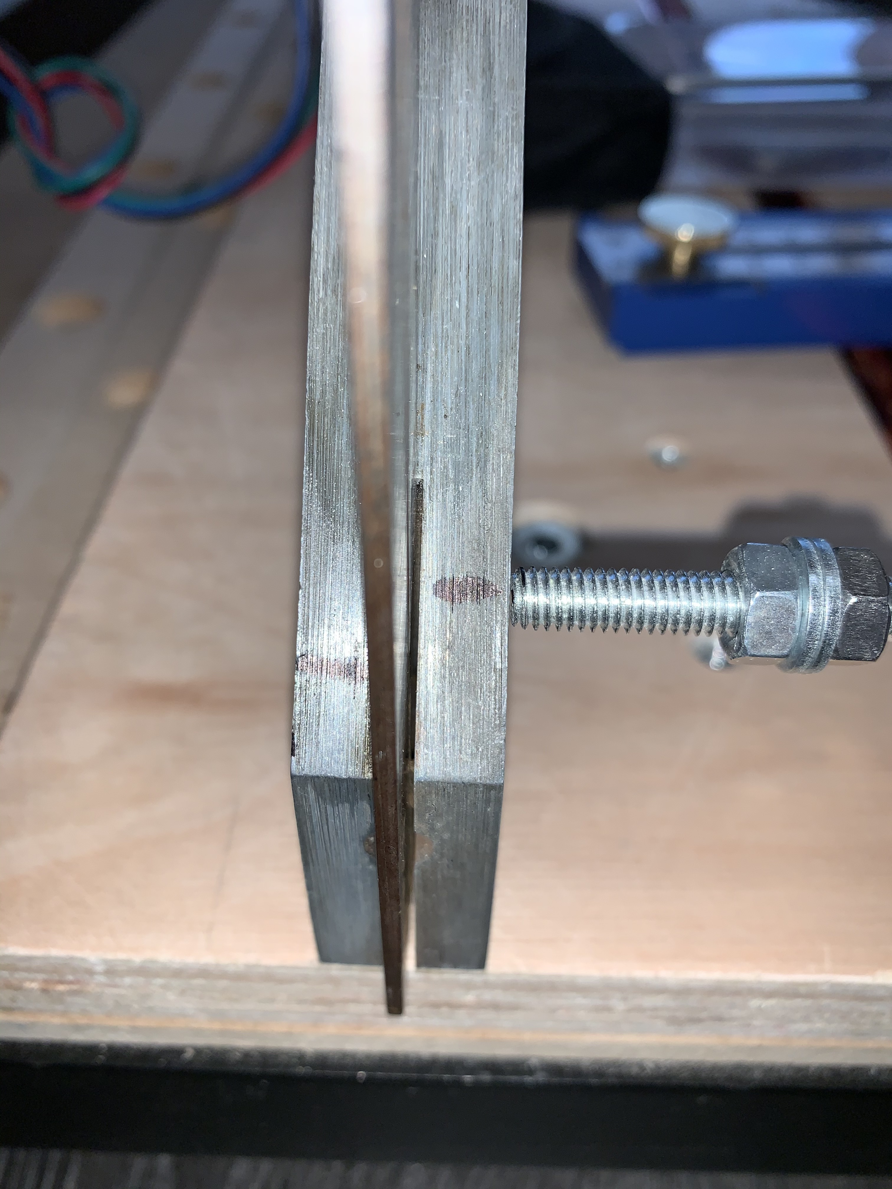
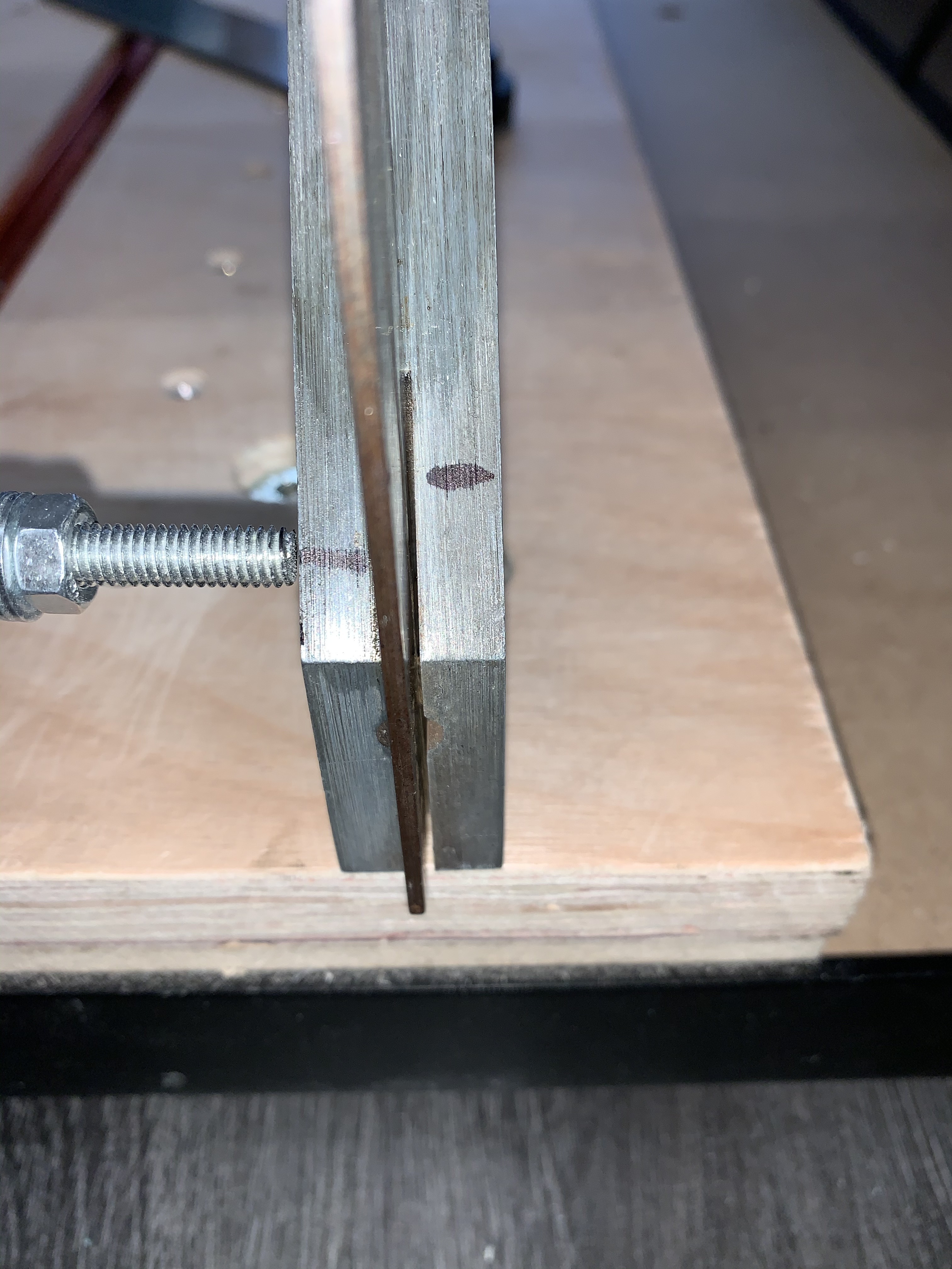
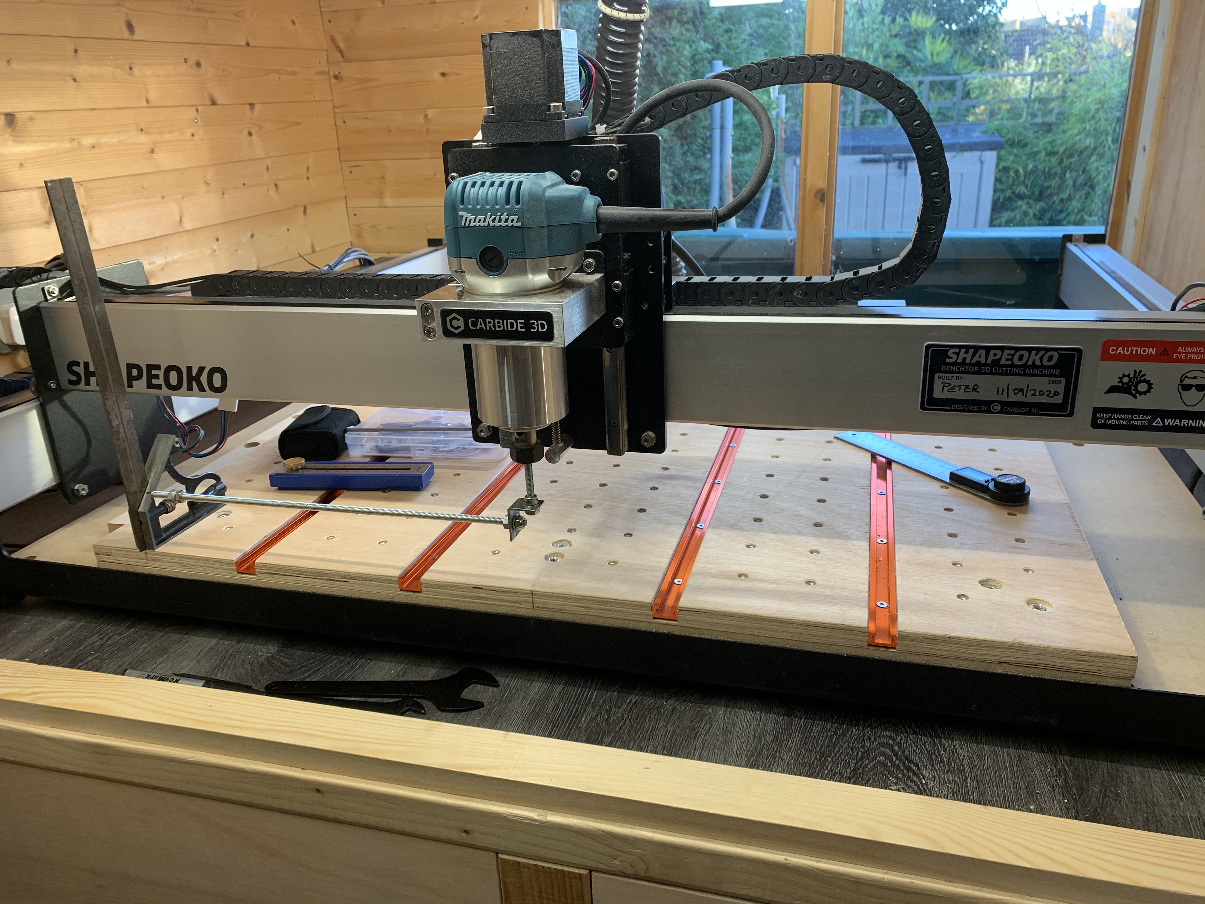
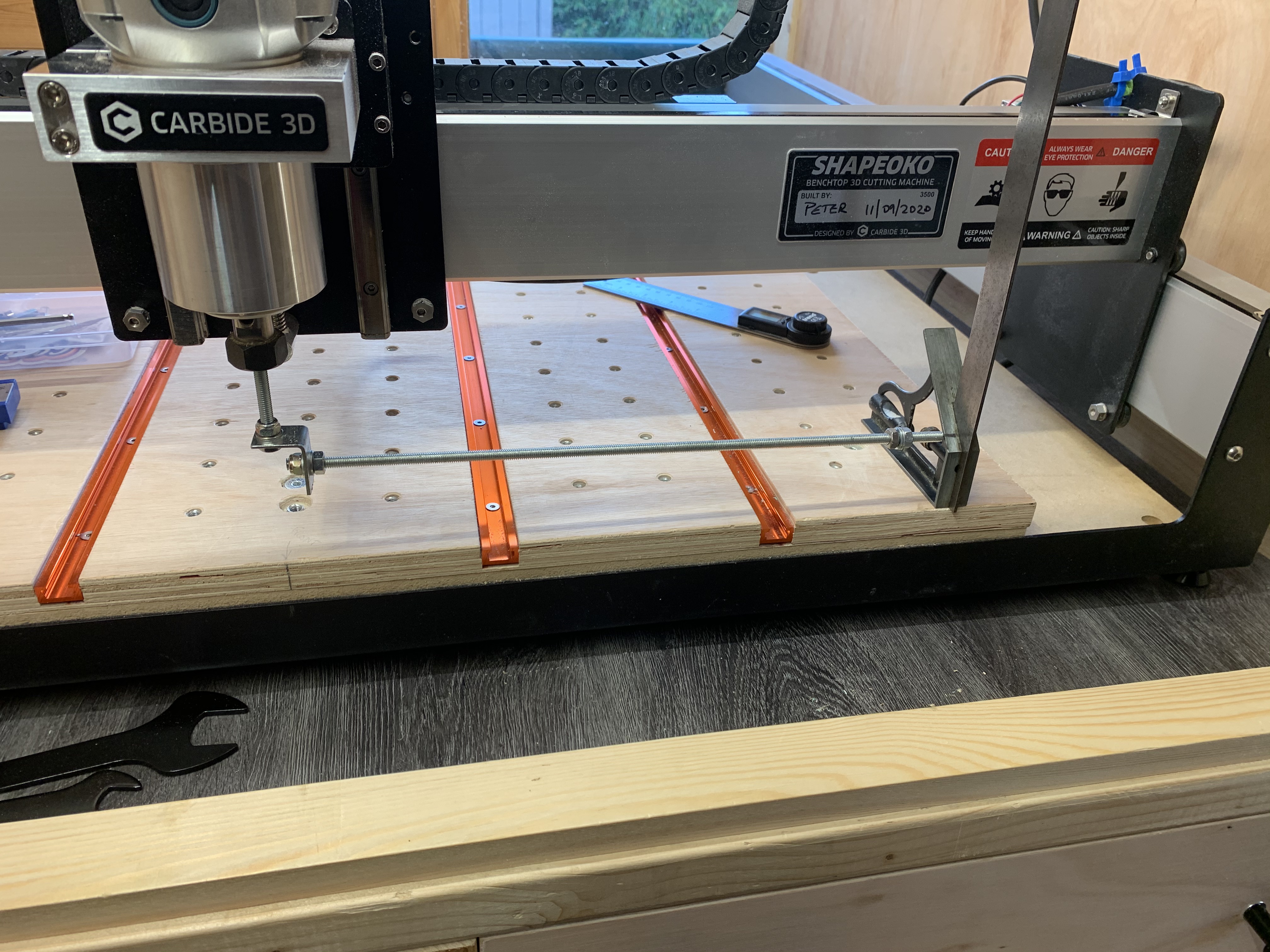
I’ve manufactured a tramming setup using a length of 6mm threaded bar, an ‘L’ shaped bracket and a 1/4" bolt. I’ve ordered a DTI which isn’t due until Monday, so thought I’d check the tramming with a square. Oops.
Firstly, the X and Y axes are level, determined bu using a spirit level, and confirmed with a digital level. awesome.
Using my ‘trammel’ I checked the spindle and, front to back, it’s great. Side to side? Not so much
The trammel indicates a 6mm difference in height between the left and right hand side, and I’m not sure where I can adjust this amount, given everything elese appears to be level. My assumption is the Z mounting.
Here are the photographs. Sorry about the rubbish measurements; I’ve had to mark them with a pen.
Concur w/ @CrookedWoodTex — I would suggest using something a bit less flexible.
As far as adjusting left–right it’s best to work from large–small:
table level? (precision has to start somewhere)
gantry level?
carriage level?
A good first start is to just loosen all the bolts, push down at each point, then check for squareness and level — gently nudge things to get to square and level, go around gradually and pull and hold each point, then begin tightening bolts in a criss-cross fashion as one would do when changing a car tire.
Guessing a bit at the length of the measuring stick, it looks like about 0.8 degrees off square which isn’t tiny but it’s not huge either given the amount of adjustment on the machine.
Did you try loosening the bolts holding the spindle mount to the Z plate and checking how much movement is available?
OK, I know where you’re all coming from with the wobbly stick bit, but there is no real weight on it - apart from it’s own - and moving it from left to right (or right to left!) doesn’t put any additional weight on it, surely? (To be fair, the context photos don’t show it very well. I’ll have a look to see if I’ve got any mild steel or aluminium bar and redesign it tomorrow). And although the indicated difference is 6mm, that’s only 3mm per side, so wouldn’t ‘rotating’ the Z plate a tad help? (as per @LiamN’s comment). There is a ‘tramming’ plate provided with the Z-Plus (I don’t know if there is for other machines), and I wonder if there’s any adjustment with that?
I spirit-levelled the baseboard (not the waste board), Y1, Y2 and X axes, and they were all level (Y2 was showing 0.1 degree, the Y1, X and waste board were all 0.0 degrees). Thinks: I might look at lifting the waste board off so I can check the machine for flatness. The waste board is 18mm ply, so I’m not overly confident that’s level.
I did check out the e-book section setup and tramming, which is where I thought the bar would help.
One other thing while we’re here: Whilst I was building the machine, there were warnings in the instructions about overtightening the screws when mounting the carriages on to the aluminium extrusions, so I was really careful about that, but when I was checking for tightness while carrying out this experiment, the screws weren’t really that tight, and I definitely checked them. Has anyone else experienced that, please?
Not yet, but the spindle mount is fixed to a trammel plate, which is then attached to the Z plate, so I’m wondering if there might be slightly more adjustment there?
A possible tramming error that might be introduced is that the photos show that you are using a “bolt” in the router end. That could introduce some error if it was bent a little, and the error could be dependent on how that bolt was tightened into the collet.


 6mm seems like a bad number.
 I might look at lifting the waste board off so I can check the machine for flatness. The waste board is 18mm ply, so I’m not overly confident that’s level.