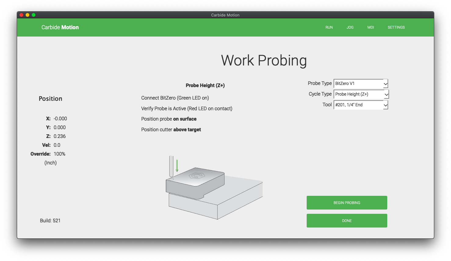
tl;dr bitsetter is off casing Z to go deeper than it should.
After starting a cut yesterday I noticed that a pocket was going beyond the .20" that I had specified. Thinking I must have done something wrong. I stopped the job, powered down the machine, and started from the beginning. Power on, initialize, correct endmill in the router, and the bitesetter did what it does. Next I used the BitZero to get x,y,z, and ensured that I had the correct endmill selected there. The BitZero was properly placed on the material. All those steps were completed with the previous job too.
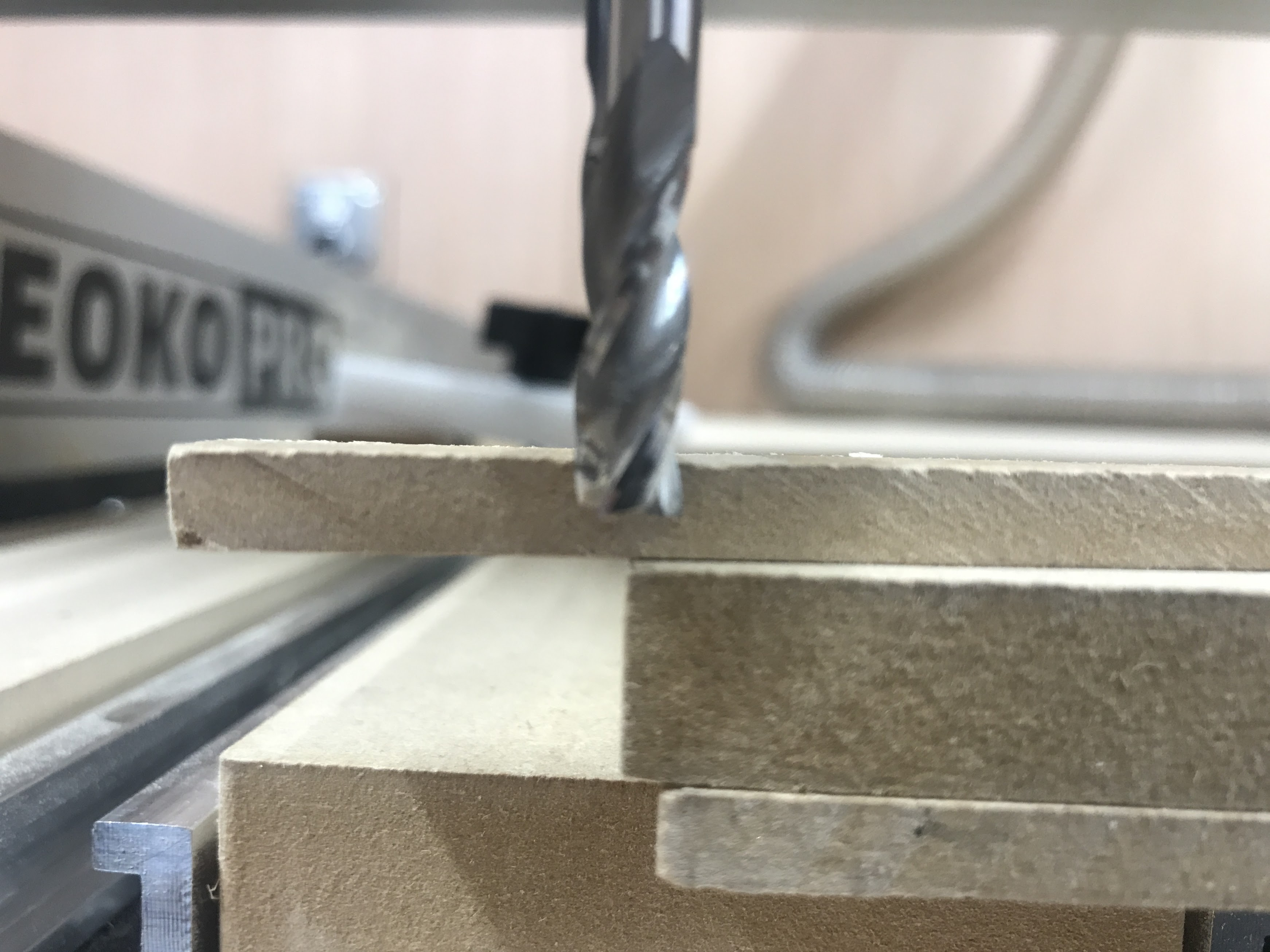
I jogged the device to the center and used the rapid movement back to x, y, and z to see if everything registered properly. What you can see in the photos, is that the z is not at the 6mm mark. The endmill is against a .25" piece of MDF for reference as I did not have a ruler that would fit in the tight space.
It could be that you have lost Z steps while dragging across the material. Do you have a retract height setting that is too low to pass over your surface? The machine will go to that height before performing rapid moves between cuts.
Good question. The retract height I’ve been using is 0.1250" which is why I think it barely scratches the face. The bigger question is, why is the bitzero not registering Z at 0?
problem in the zeroing procedure itself => it does not seem to be the case, if you installed the probe overhanging the corner and choose Probe XYZ. This is best investigated by jogging to the surface after using the probe and before running the job, to triple-check the surface is at 0.0. If is, but then the cut is too deep, then focus turns to the BitSetter. If it isn’t, then focus on the probing/zeroing part.
not following the BitSetter workflow, for example swapping the cutter without using the Change Tool button or when prompted => it does not appear to be the case here
a problem with the BitSetter “sticking”. Does the plunger mechanism feel smooth ?
if you want to eliminate the BitSetter hypothesis, you can also temporarily disable it in the settings, and run a single-tool job.
I am glad I read this article. I would have missed the probes position. Of course I have never used the probe height only the probe corner. I don’t think I will ever use the probe height setting now as I like to double side tape my probe in place during the probe and putting it on the surface rather than the corner for me would suck. I will stick probing the corner always.
Although, I do realize why they do that. If your start point is in the middle of the job you don’t want to go to the corner to probe so it would be natural to have the probe sitting on top of your job, hence the needed offset.
@Julien
I have been struggling with the Z height since day one with my machine. I have double and triple checked my procedure and still cant figure out why it is not giving a proper zero. It seems to be worse when I use the 60° cutter. It is almost as if it can’t calculate the change from the probe to the bit during the tool change. I probed with the BitZero V2 using the x, y, z option and once complete and verify the 0,0,0 dimensions of the probe and they are correct. Then when I start the job, it asks me to change the tool and I follow the prompts and then start the job. I now pause and stop the job immediately and verify Z0 and it can be off either up or down or correct as it has done a few times. I do this so I don’t lose more material as I have scrapped quite a few pieces. The confusing part is that the Z0 is good sometimes from the start. And if the Z0 is good, it stays correct through all the tool changes during the job.
A couple days ago, I ran a part and the Z was 15mm to high. Today I ran my first part and it was around 1.5mm high. The second part I ran today was 11mm low. I have even manually set the zero after stopping the job to place Z0 properly and that has worked until this last time. After I manually set the zero, and then went through the prompts to change the tool, it was 6mm too low and I scrapped out another piece of material. This time, I even set the Z0 with the 60° tool so the bit setter was registering the exact same tool that was used to set Z0 and it was low by 6mm.
X and Y have been basically perfect so this is just a Z issue.
Hopefully this wasn’t too jumbled and makes sense, but there is definitely something wrong. I hope it is just a simple oops on my part, but it is not looking that way so far.
Step-by-step write down each step you take after the machine’s initialization / homing routine. Write down the words from the screen prompts, too.
From you’re posts, we’re assuming that you both have the BitZero and BitSetter devices properly installed, but check this in your machine settings. If you don’t, nothing said here will make any sense.
Be sure to indicate the location of the BitZero including whether it is completely on top of the part or hanging over the edge of the part.
Indicate whether you use a bit for the XYZ procedure or whether you use a machined dowel and what size.
If you have the newer version 2 of BitZero, does it move during the operation?
Each step can then be evaluated in order, but remember the old saying, “Garbage in; garbage out”.
@WillAdams@CrookedWoodTex
Will,
Thank you for this calibration tutorial, but I want to point out one critical thing. The issue isn’t between bits during the running of a program, it’s only on the first bit used in the program that I am having the issue. Once the depth is set properly, the bit changes have been exactly the same depth. Sometimes it takes 3 tries to get it correct, but once it is correct, it stays correct throughout. I have made a handful of signs and the pocket cut out with a .25" endmill has the exact same depth as the letters that were cutout with a .125 bit and then a .0625 bit. (Which is what I wanted as the letters were cut to the same depth as the pocket)
This makes it very confusing as to where the problem is originating. I have manually set the Z0 using the first bit in the program and after the start job menu asks to change the tool, the actual zero was different as I described in my earlier post anywhere from positive 15mm to negative 11mm. (As you can read below, this has increased to a positive 25mm as of today)
Here is what I did step by step today. (I used your calibration file, but tweaked it a bit to show the depths. The top
Connect to cutter, then initialize machine
Tool Change required (.25 #201 bit was already installed so I hit resume)
Took out .25 endmill and replaced it with the probe
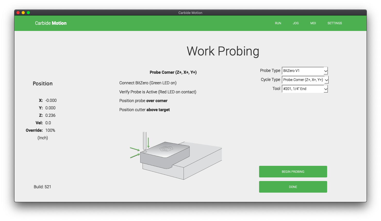
Placed BitZero V2 on corner of piece, connected ground and placed probe inside bore .200 deep
Probed the part using the Probe Corner (Z+, X+, Y+) option
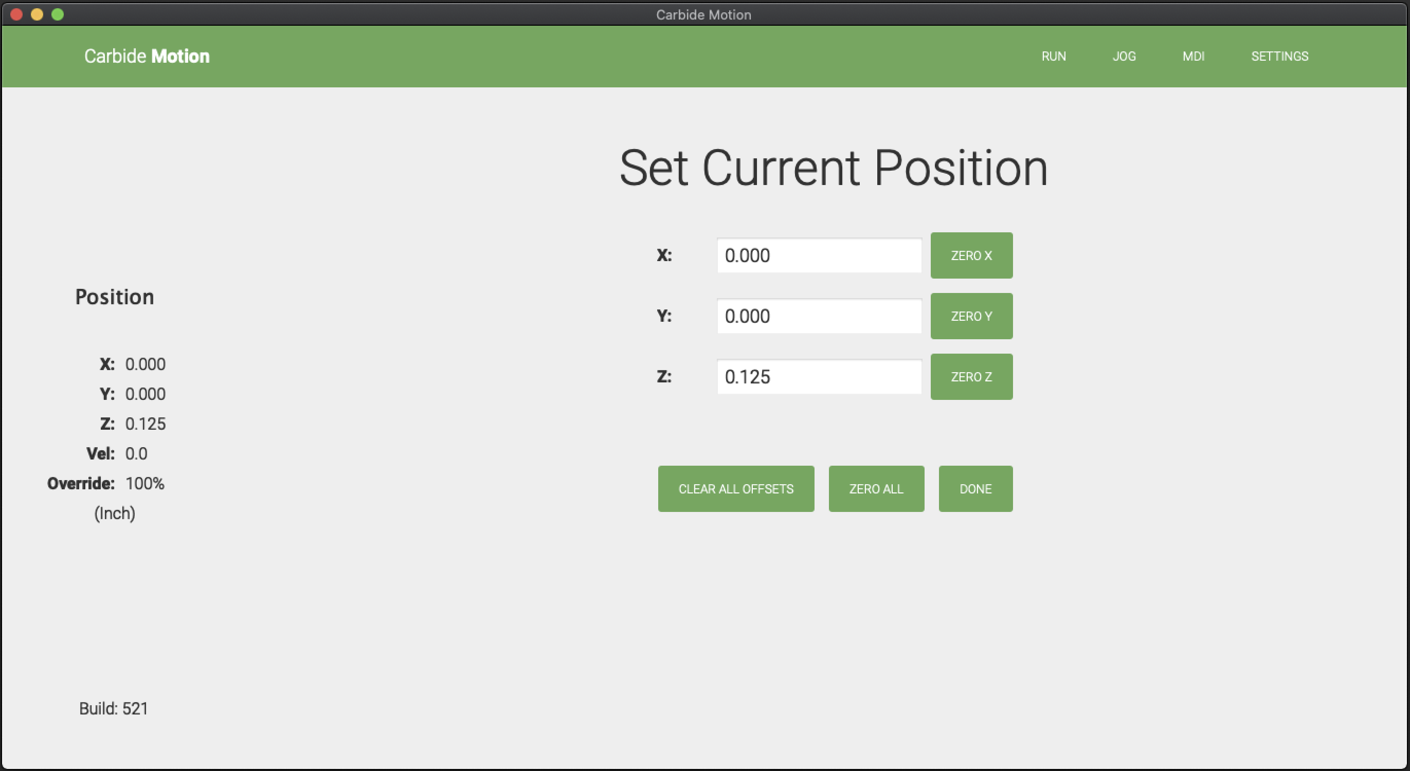
Double checked the Set Zero tab and the probe was at 10, 10, 19 like normal after probing. Clicked Done, not zero all to make sure nothing was re-set
Double checked the actual X, Y and Z 0 on the part after removing the BitZero and it was good. Z0 might have been off +.025mm at most
Load New File
Start Job, Start
Tool Change Required, Insert Tool #201, Clicked on Resume
Tool Moved to Bit setter and Zero’d itself and moved to spindle on operation and cut part.
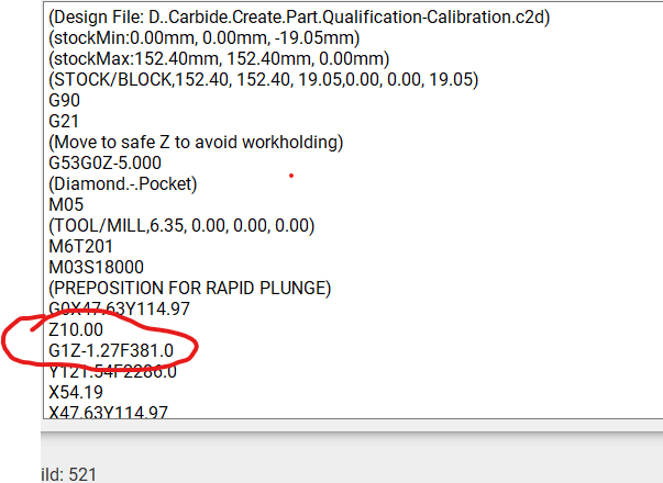
Turned on router and started cut sequence. Part programmed to cut .05" (1.27mm) deep with 10mm retract clearance and confirmed this in G-code
Part cut .263" (6.68mm) deep and I aborted the cut sequence
Checked the physical Z0 after aborting the part and at the top of the material it is at 5.5 (which matches how much deeper it cut the part. (6.68-1.27=5.41)
Re-probed the part back and repeated step 5 thru 12 (Measured the length of the probe sticking out of the collet at 23mm
Started the next job and measured the length the .25" bit is sticking out from the collet is 29mm
Had to abort the next job because it was cutting the part .375 (9.5mm) deep
Manually set the .25" bit at Z0, still utilizing the X0 and Y0 from the BitZero
Part cut just over 1mm deep or about .05", which is what the program calls for
Changed bit to .125 endmill #102 as per the program and it used the bitsetter like normal
Part cut from .05 deep to .100 deep as programmed
Changed the Bit to .0625 endmill #112 as per the program and it used the bitsetter like normal
Part cut from .100 to .150 deep as programmed
A) Tried a slightly different method after probing X, Y and Z0 this time. I went to the Load new tool option before clicking on run job, but the bit was at Z0 on the computer screen and was 25mm above the part.
B) Re-loaded the bit sequence again without using the BitZero and it was still at 25mm. At least it repeated as I didn’t move anything.
C) Zeroed the .25 bit manually, clicked run again, clicked load new tool again and it was at the proper Z0 this time.
Is something here that shows that I am either doing it wrong or the machine is not cooperating.
Is there a way to start over and basically reboot this thing? Should I uninstall the software and restart the machine like it is the first time I ever used it?
Thank you for your help. Hopefully we can get this all back on track!!
I think you are getting into issues by letting the existing bit go to the bitsetter then changing it to a probe (Steps 2 & 3). You should either install the probe before the first run to the bit setter or after the existing tool has been measured, using the change tool button to install the probe then have it run to the bit setter again. I think the variability is the difference in stick out from your original tool to the probe.
You are both correct that I wasn’t running the probe to the bitsetter before probing the corner with the BitZero. I made the assumption that the probe calibrated itself for the z height without using the bitsetter. I will try out your advise later tonight or tomorrow morning and let you know how it went!!
I hope this solves the problem.
I am having the same issue and it is maddening. The instructions for the BitZero v2 are non existent, so are you suppose to use the probe vs a bit every time? Or can you use a bit like in v1.
To use the BitZero with a probe you must have also have a BitSetter.
Otherwise, you cannot change the probe for a bit since it will result in a piece of metal with an unknown length sticking out of the collet. Which you’d then have to BitZero to measure.
If you are JUST doing Z probing, and not X&Y&Z probing, it probably doesn’t matter what is in the collet. A bit or probe will touch the bottom with equal accuracy.
The probe is supposed to be a perfect cylinder and therefore more accurate (than a bit) when its sides contact the inside of the BitZero V2 circle when doing X&Y&Z probing. The reasoning here is that the flutes of a bit cause gaps or flattened areas of the bit’s cross-section, meaning the bit’s current rotation in the collet can therefore affect its perceived width.
Well, that is correct only if you are executing gcode that is a combination of several toolpaths using different bits; such as end mill and vbit. Then the BitSetter is automating the bit length changes between toolpaths.
Well, that is correct only if you are executing gcode that is a combination of several toolpaths using different bits; such as end mill and vbit. Then the BitSetter is automating the bit length changes between toolpaths.
I don’t think so.
You can’t measure Z with a probe, and then change the probe to a bit, and then run the job.
To use the BitZero with a probe you must have also have a BitSetter.
Otherwise, you cannot change the probe for a bit since it will result in a piece of metal with an unknown length sticking out of the collet. Which you’d then have to BitZero to measure.
@CrookedWoodTex suggested that this is only true when there are several toolpaths.
To which I responded:
You can’t measure Z with a probe, and then change the probe to a bit, and then run the job.
Here I was suggesting that the proposition is true all the time.
The operations described here are intended to be the only thing that is happening. That is, you cannot put a probe in, zero with that probe using the BitZero, then take out the the probe and put a bit in, and then hit “Start Job”.