as requested on support…
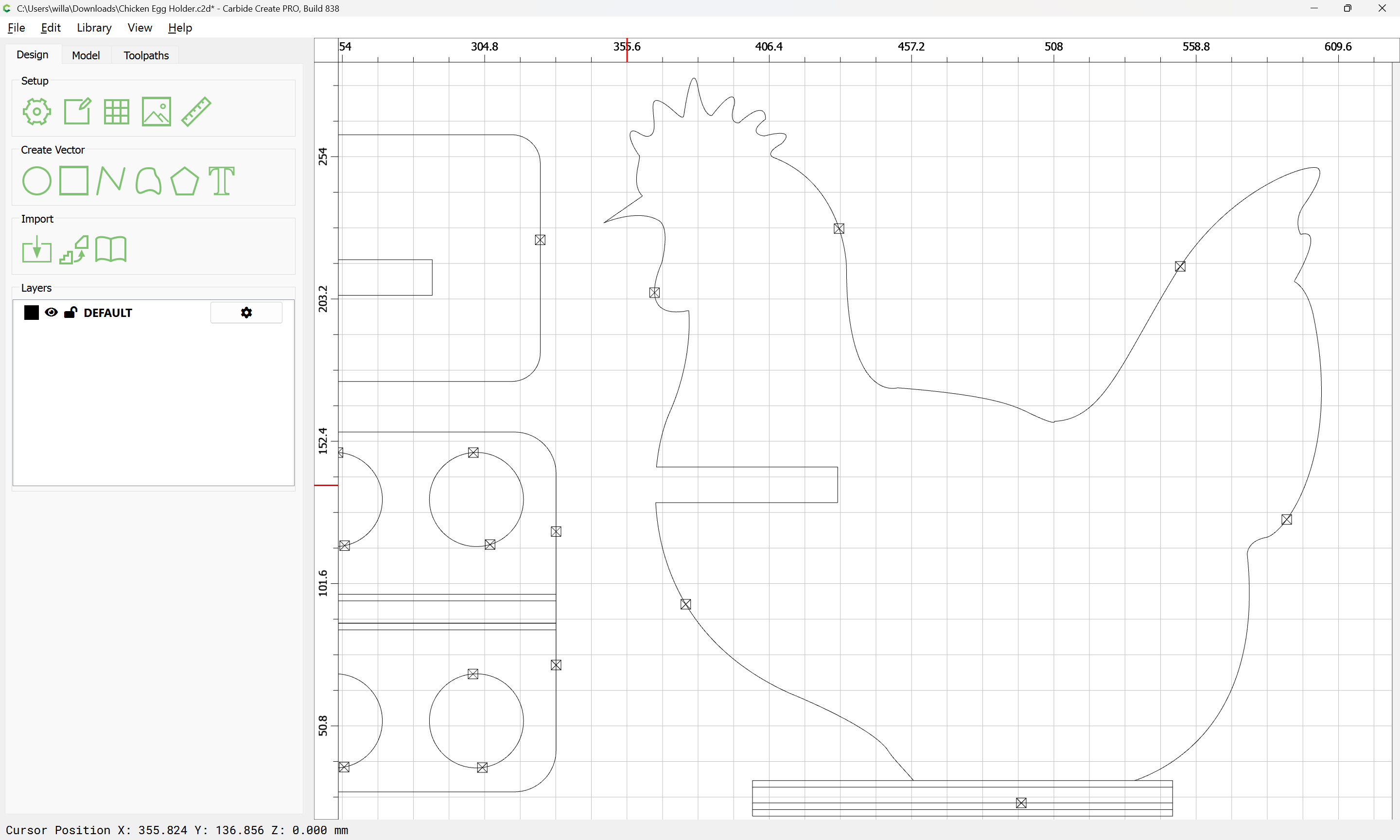
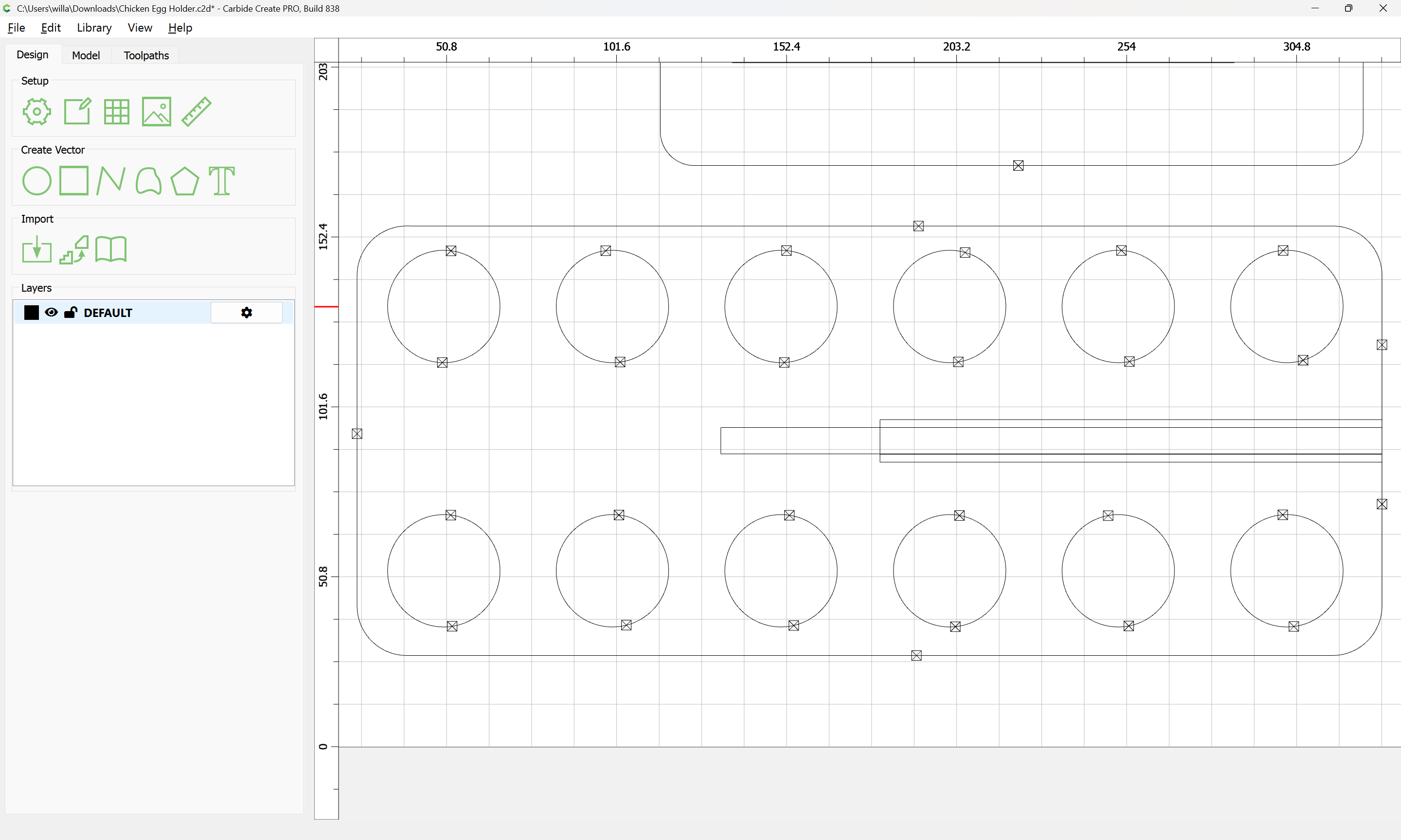
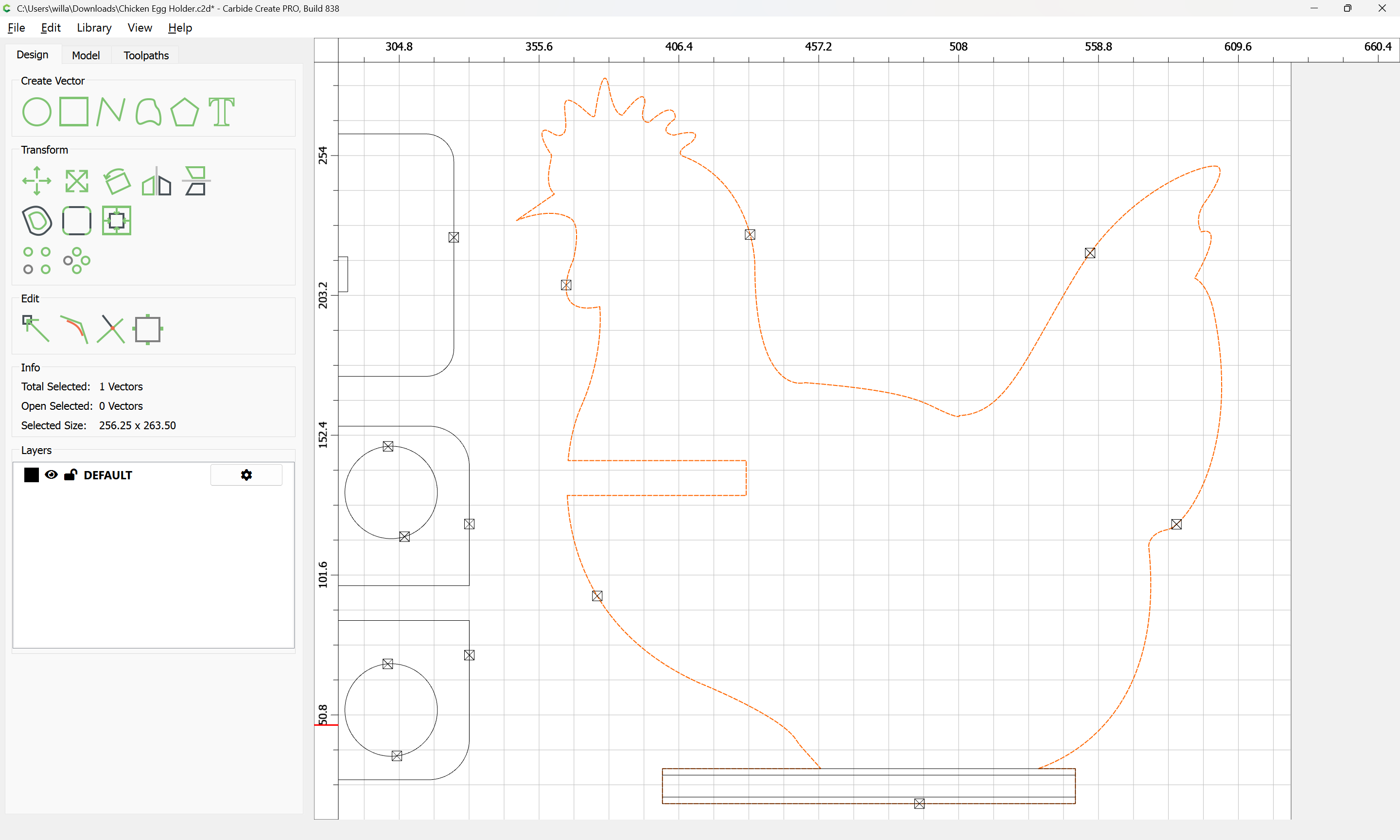
How do I increase the slot size in the attached file for the chicken, base and egg holder. The current design is a quarter inch slot for the chicken stand and egg holder. I would like to increase it to around 1/2 inch.
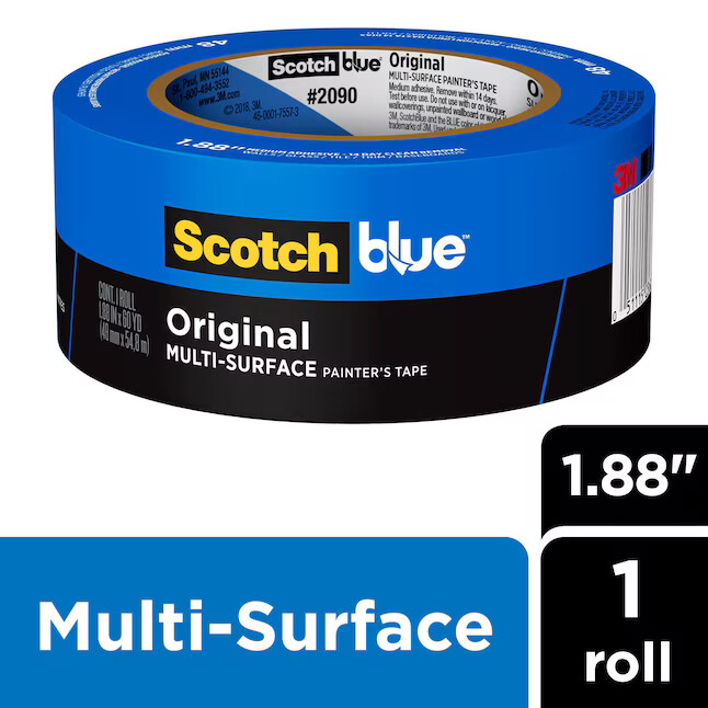
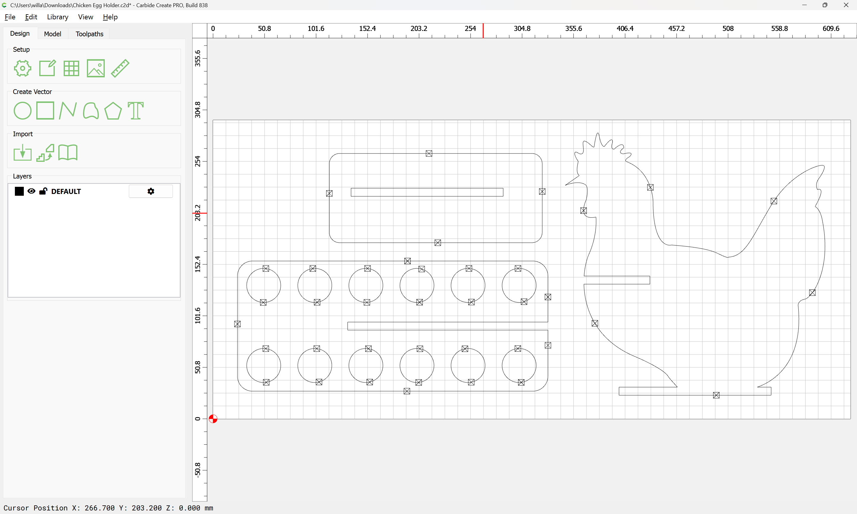
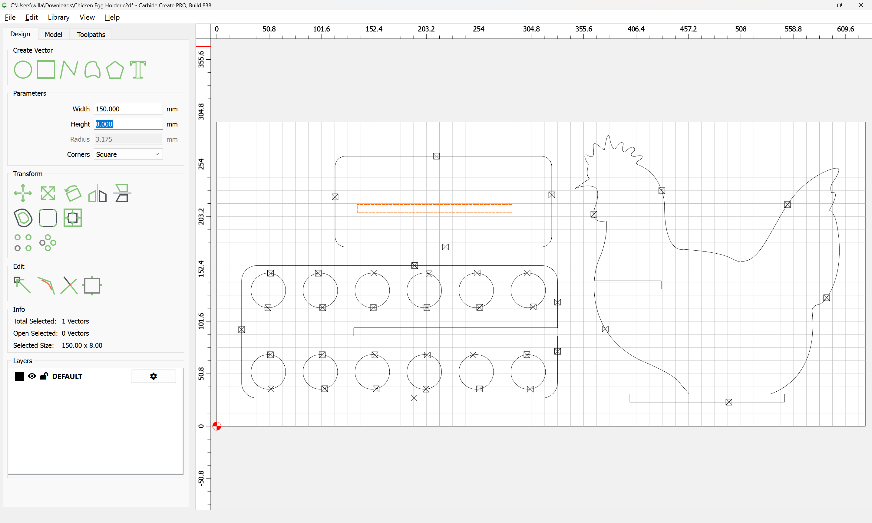
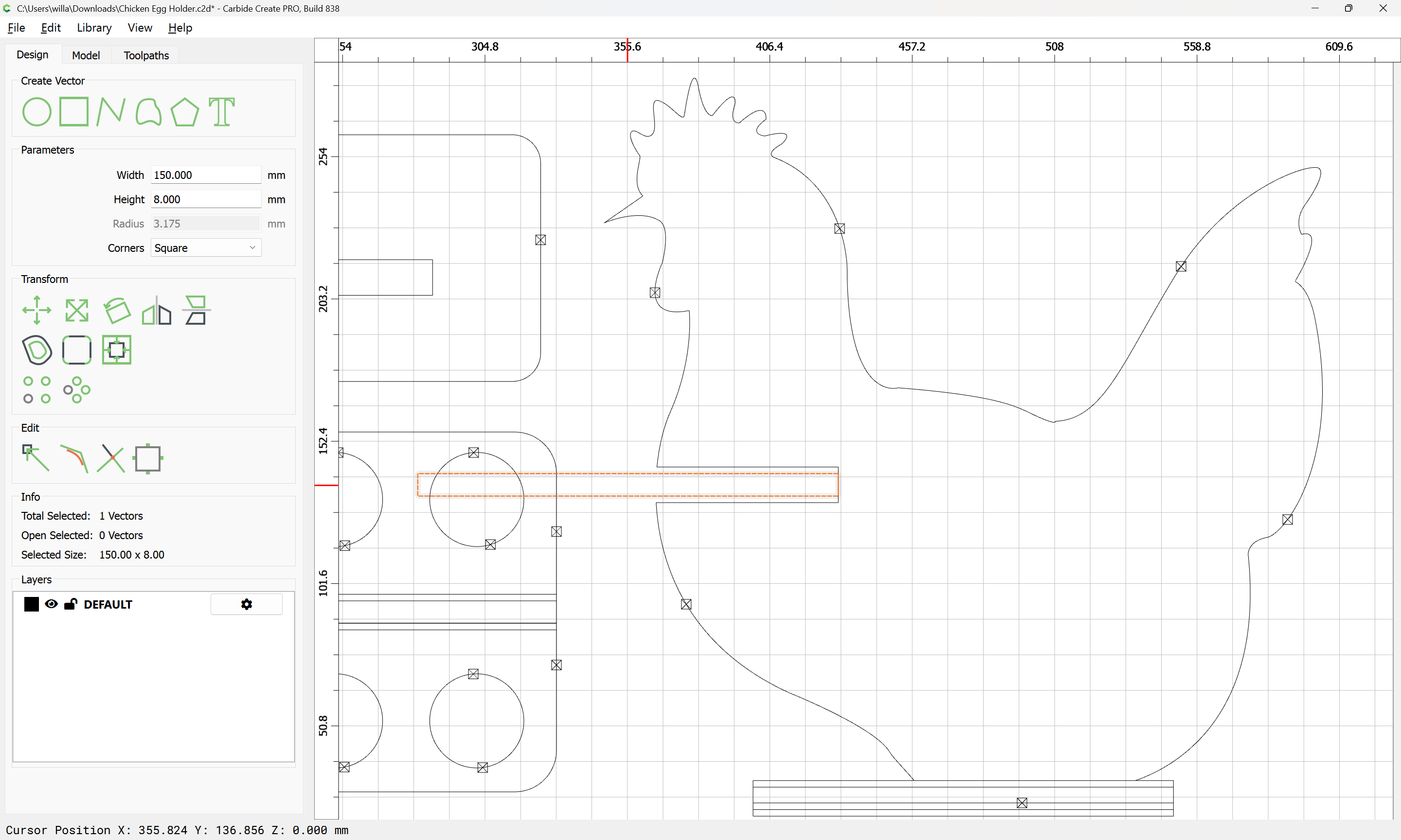
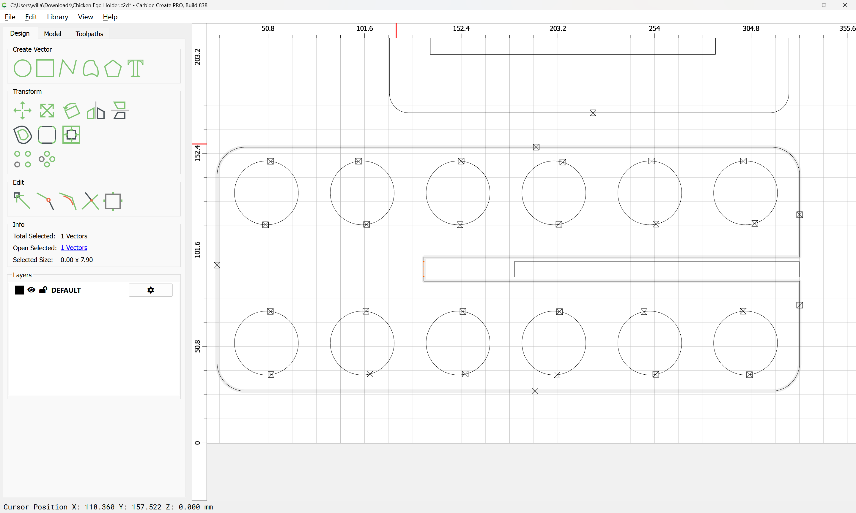
Deselect everything:
d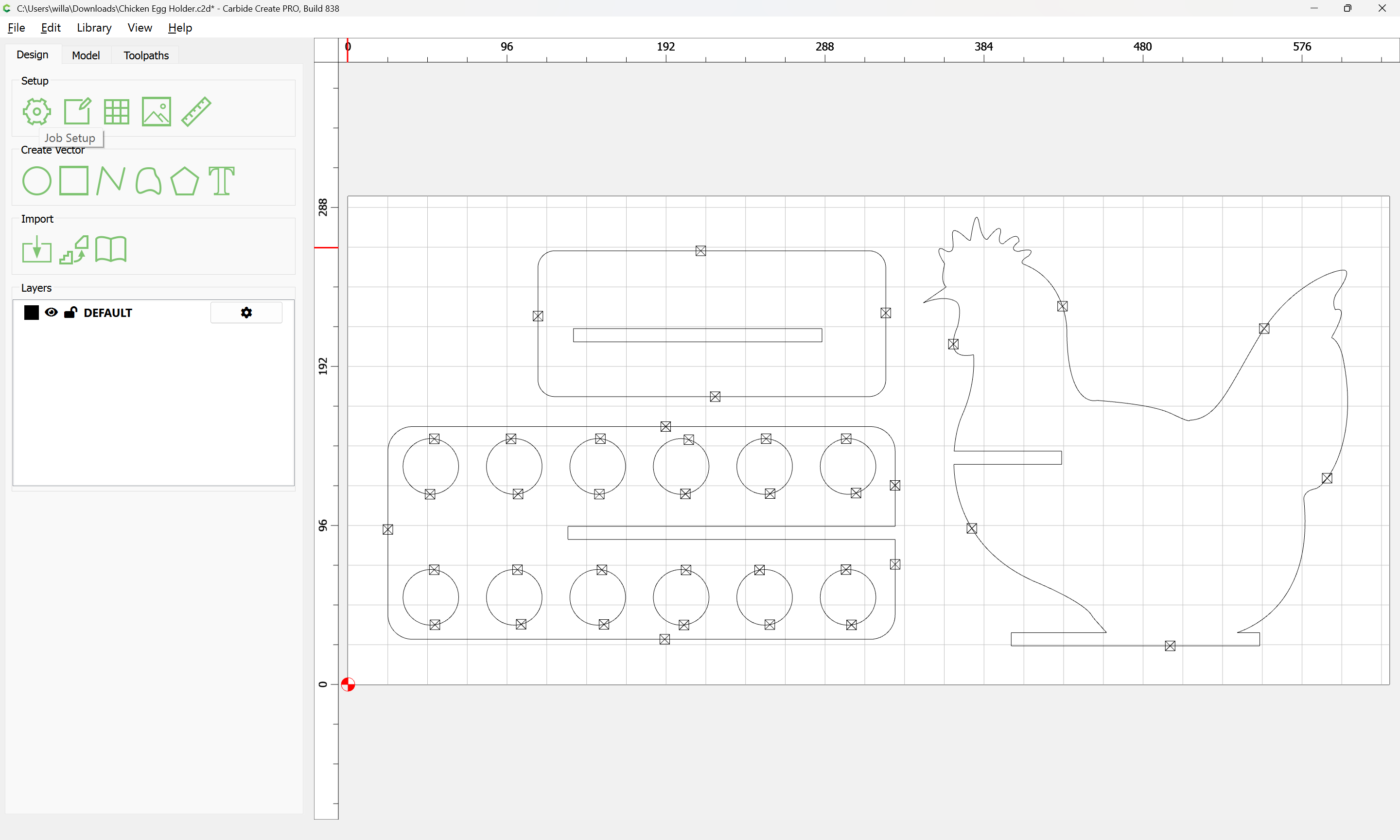
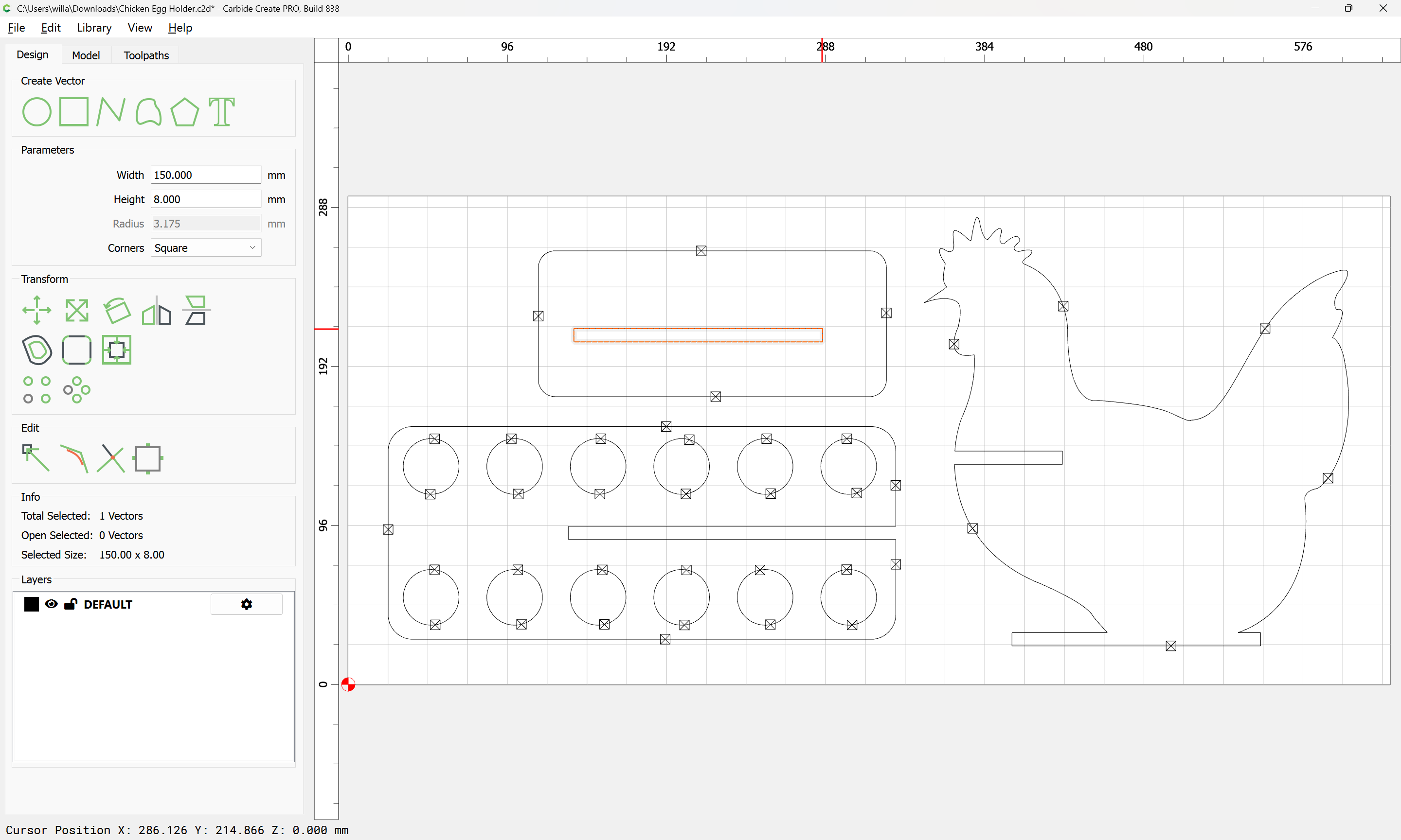
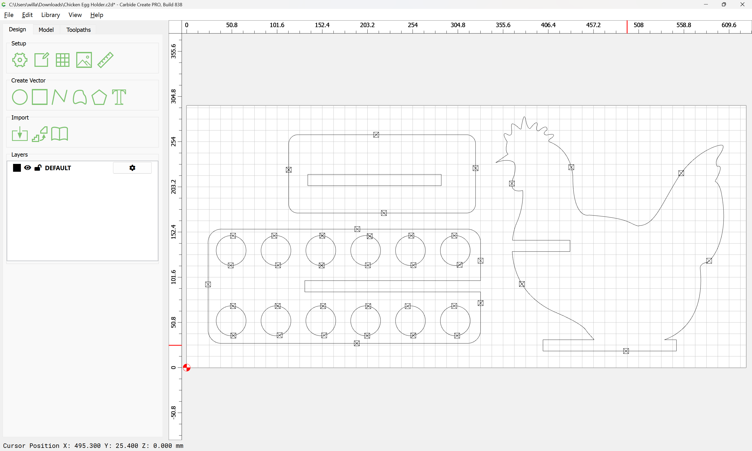
and go into Job Setup and adjust as need be::

Ok
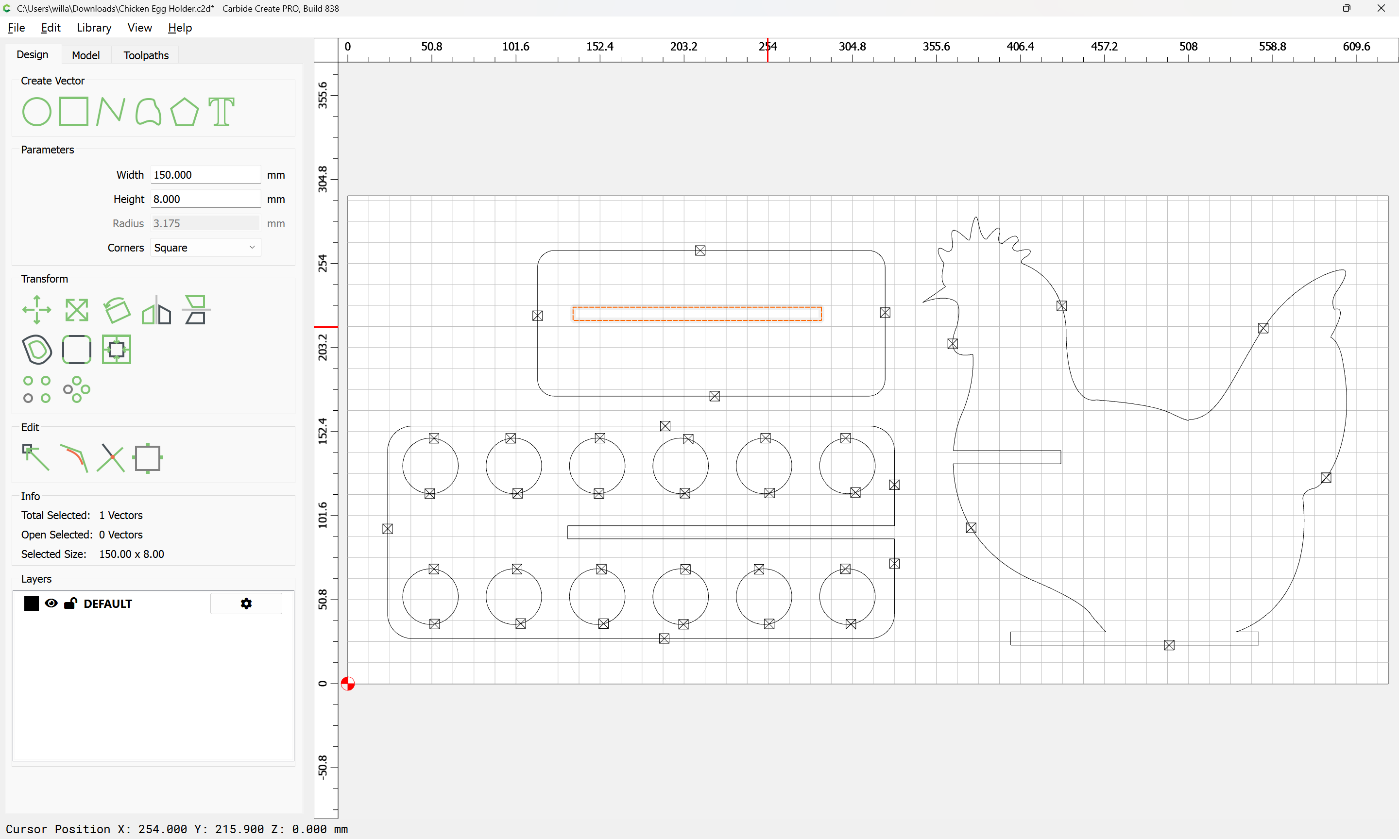
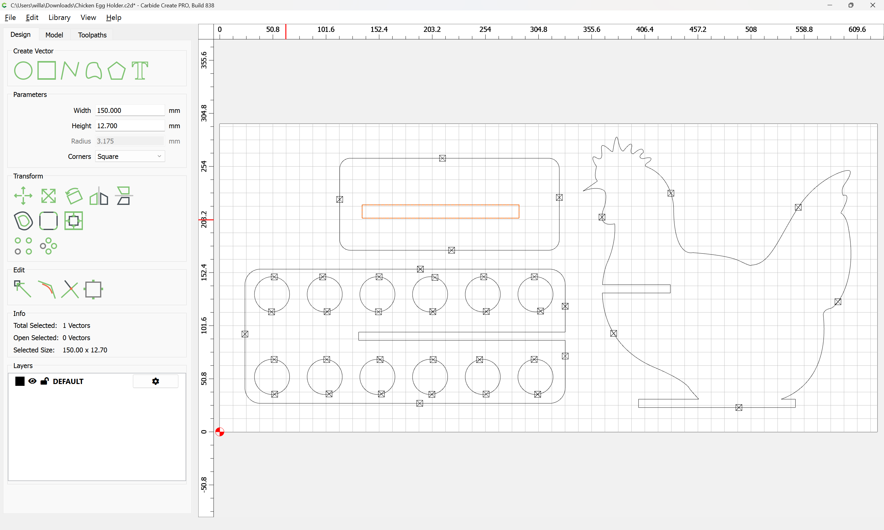
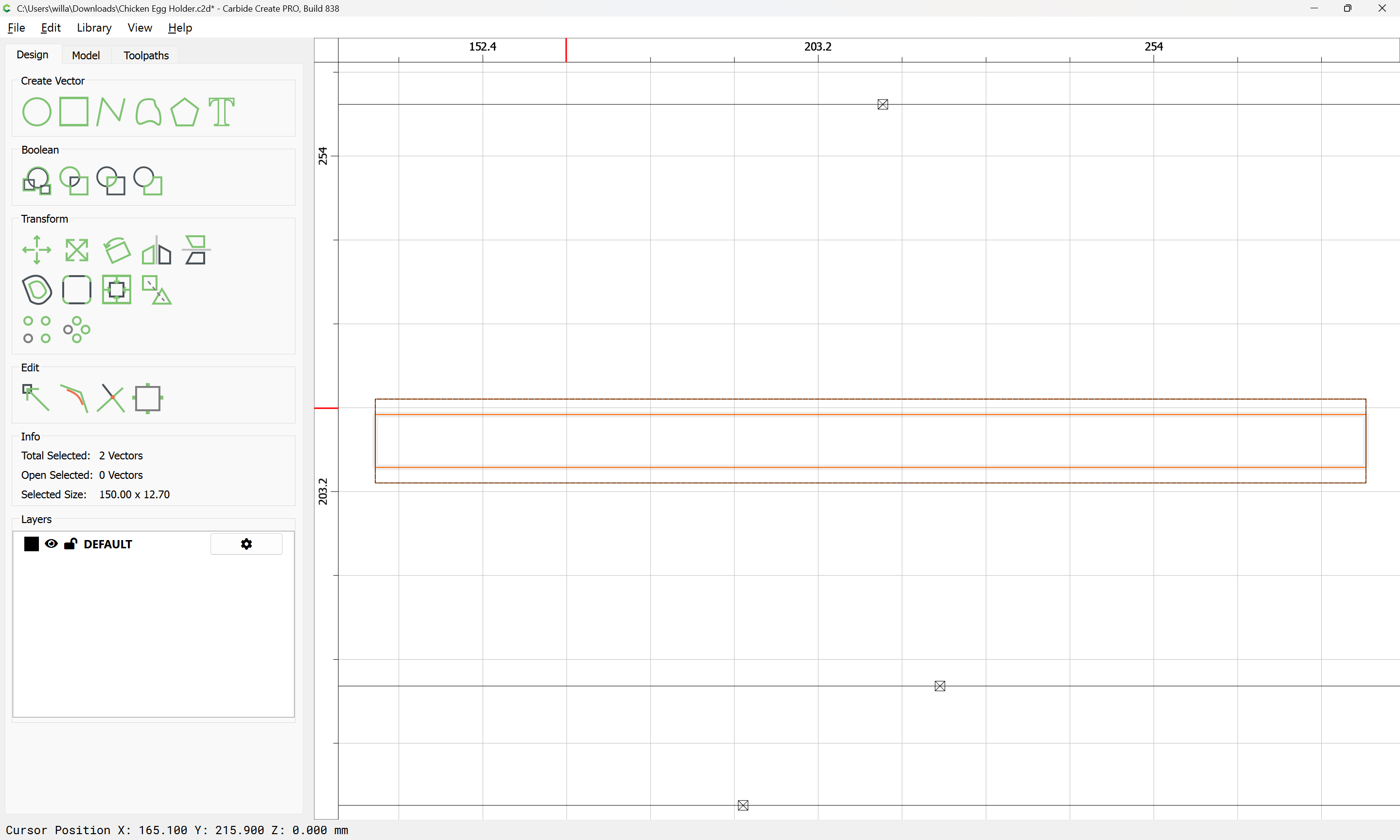
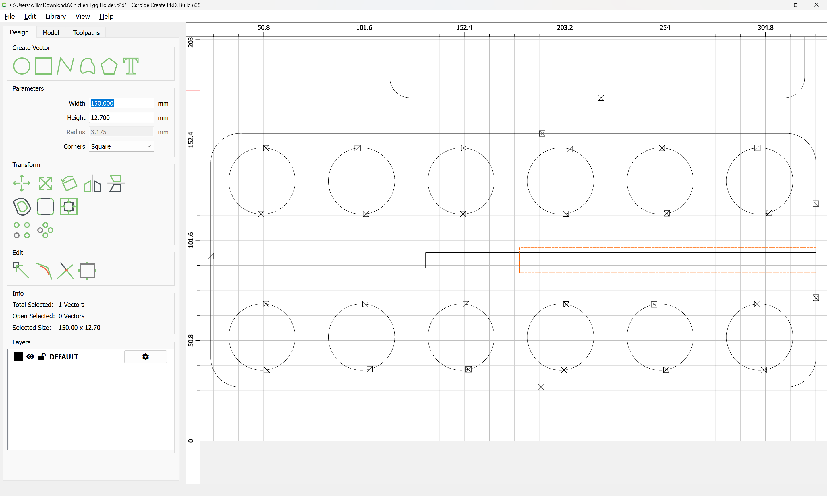
If what could be a rectangle is not:

Re-draw it:
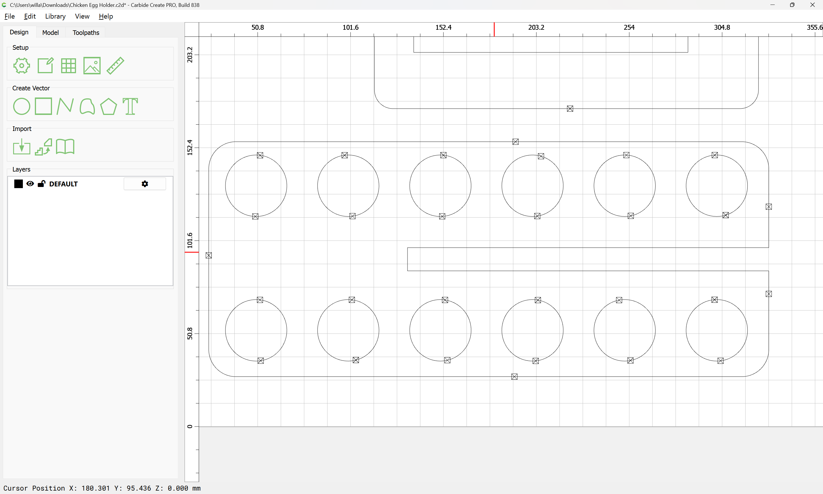
shift it one grid space using an arrow key:
Select the original:
delete it:
select the original, and nudge it back:
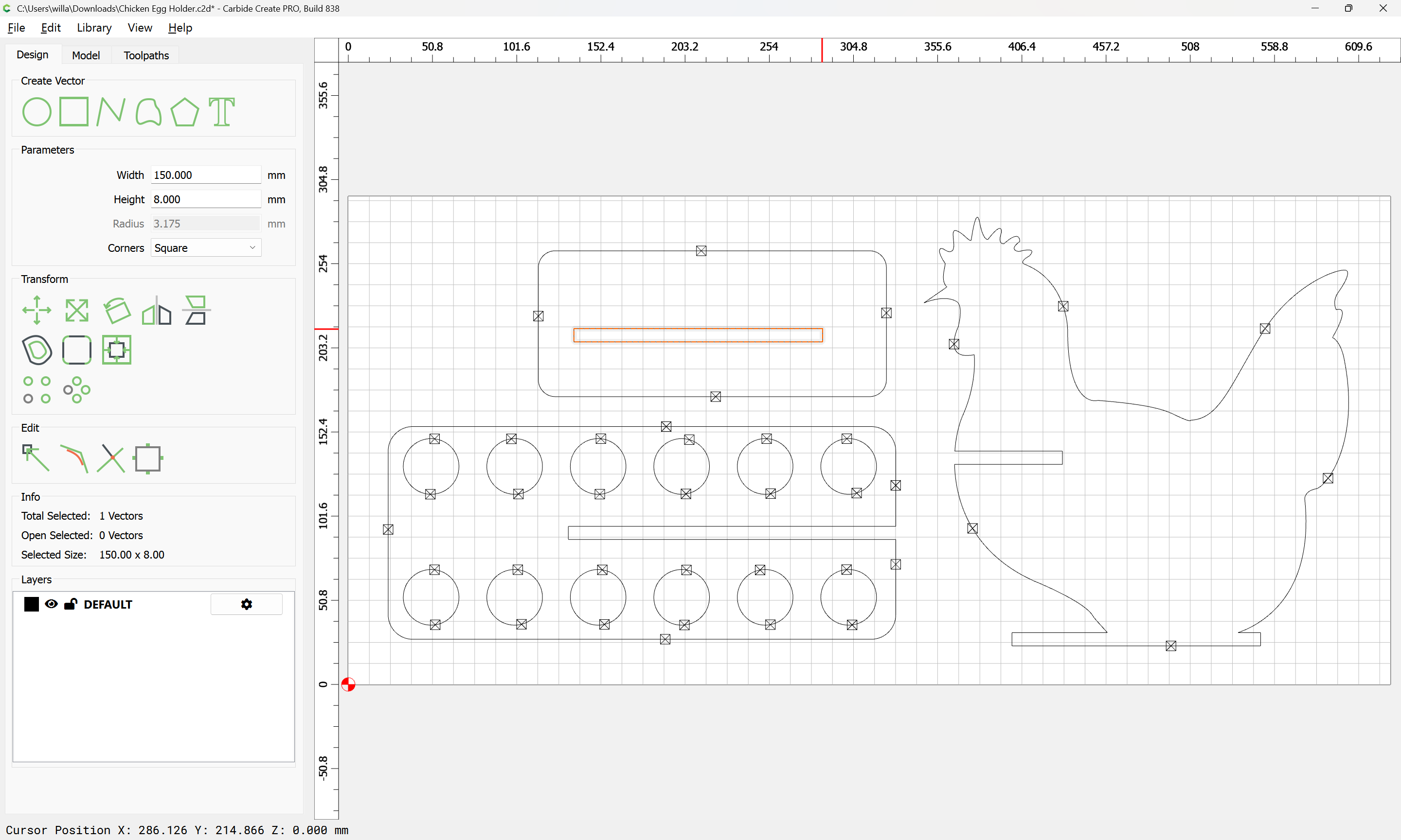
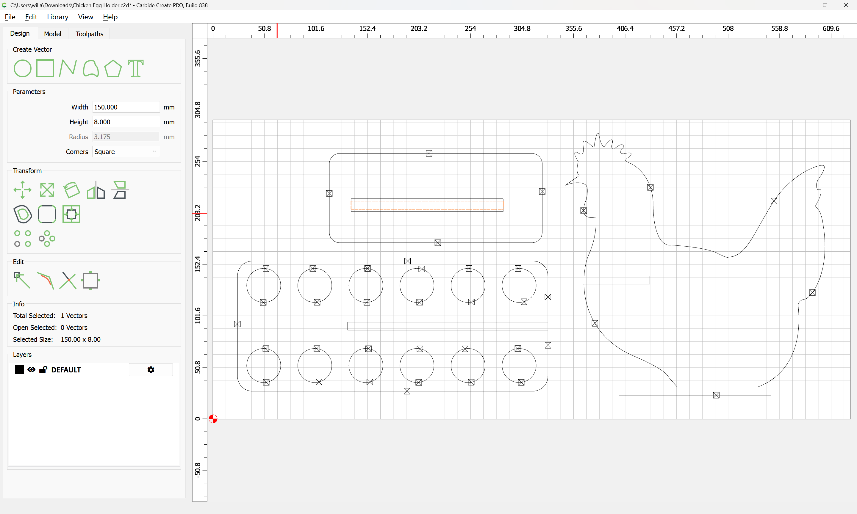
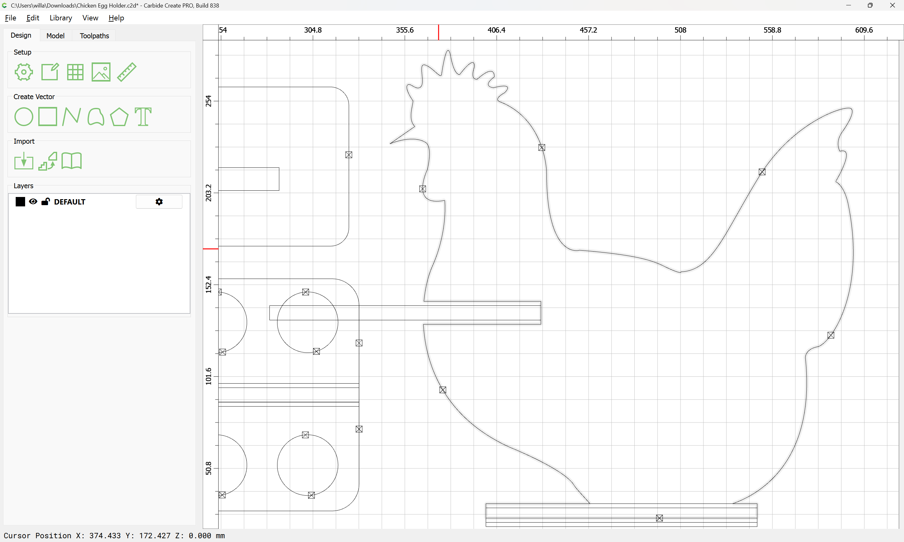
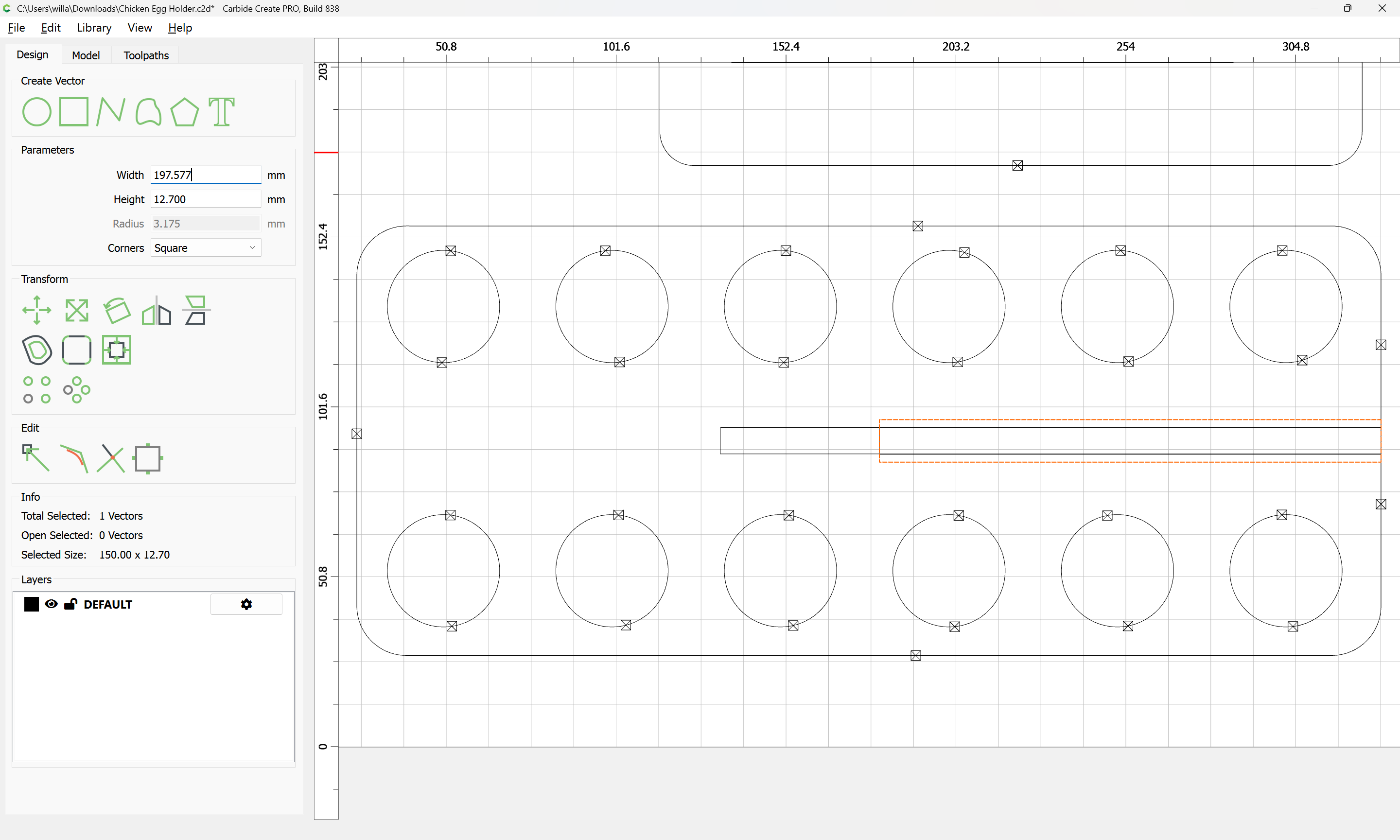
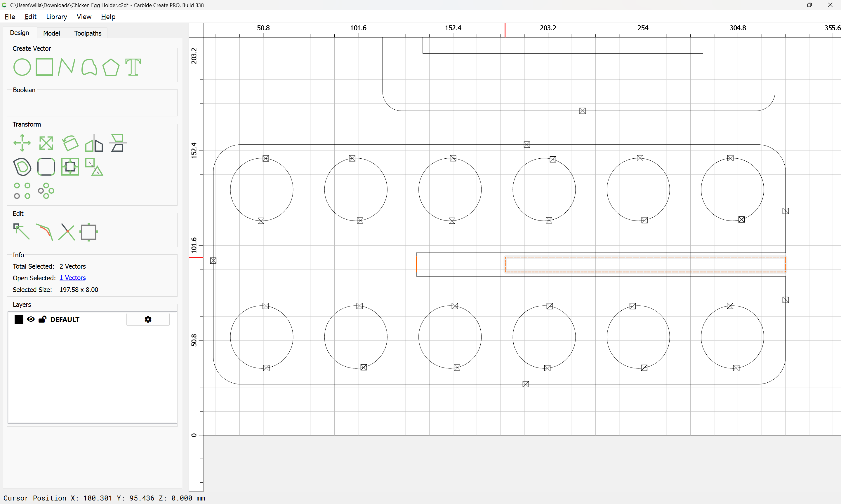
Then adjust the height:


Then, because it will be useful to have that original dimension as a reference, copy-paste the rectangle in place:
Change its height back to the original:
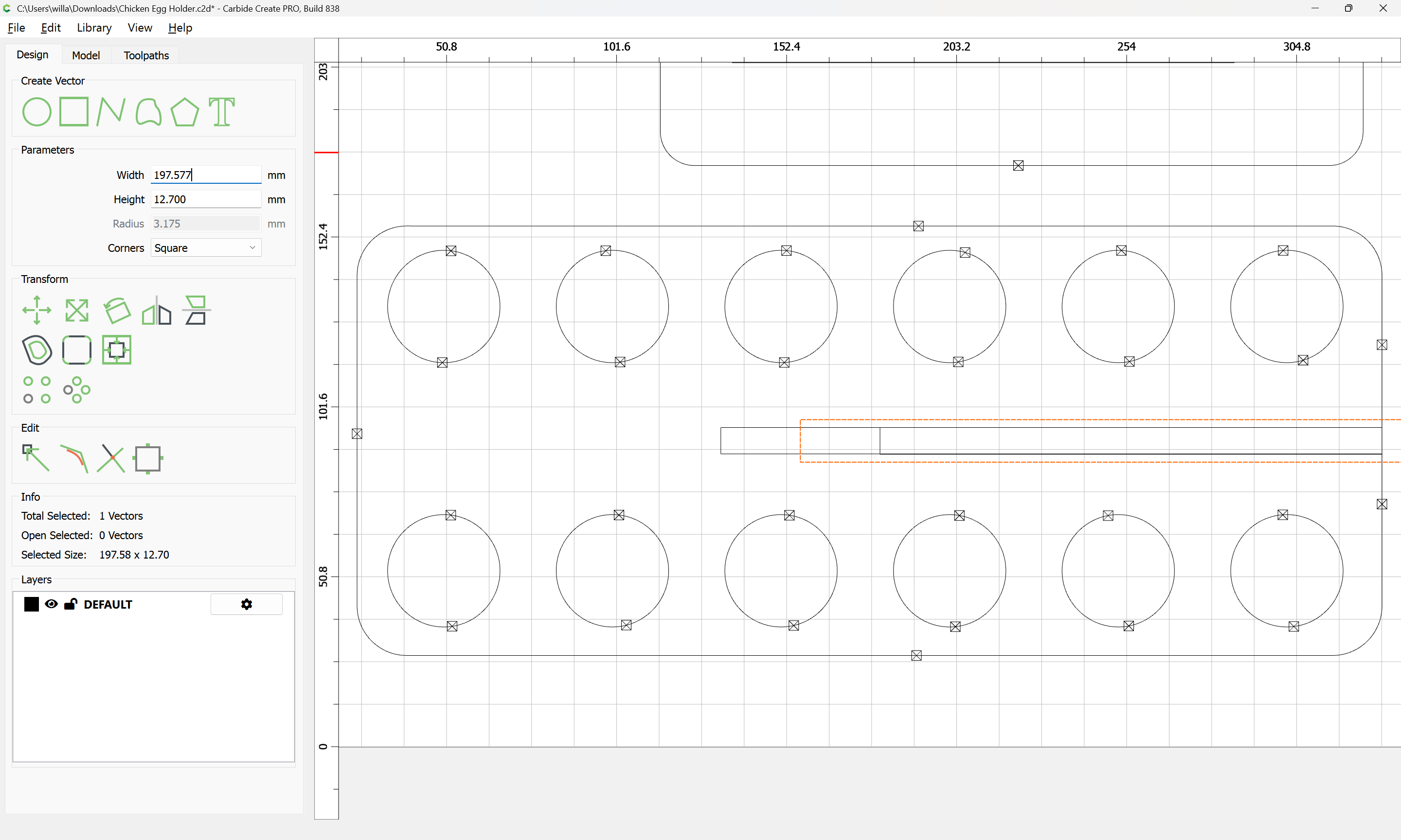
then copy-paste the re-sized duplicate so as to have a copy:
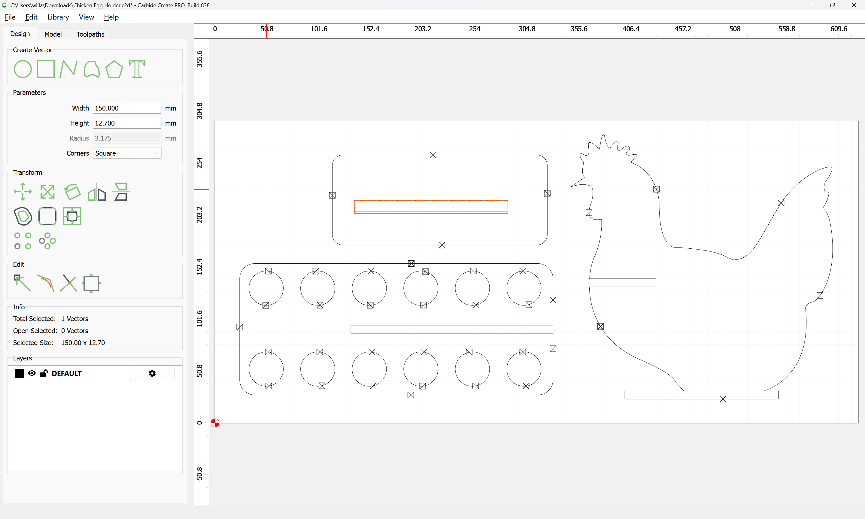
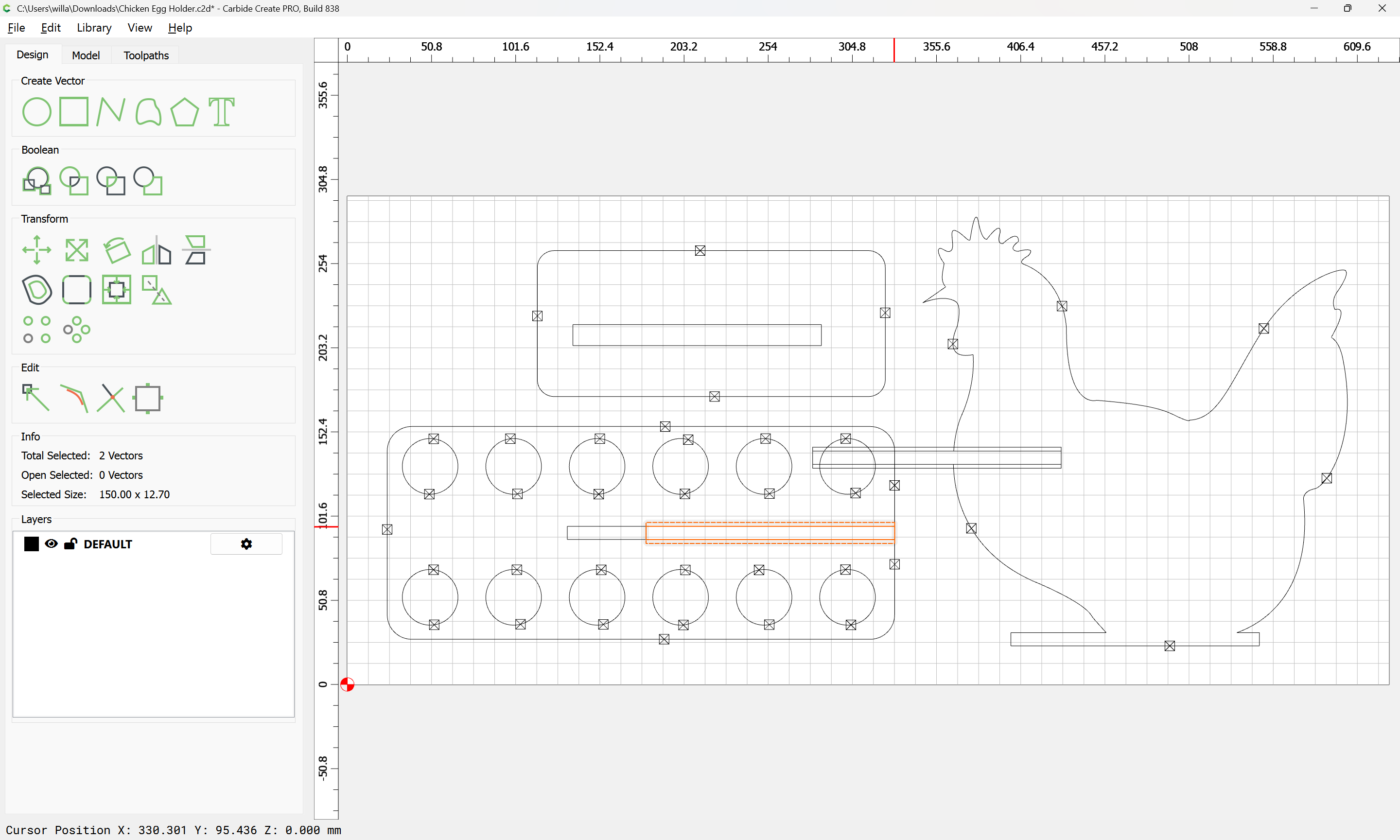
Then add the original size duplicate to the selection by zooming in and shift-clicking:
The duplicated construct may now be dragged into registration with an area which needs to be modified:
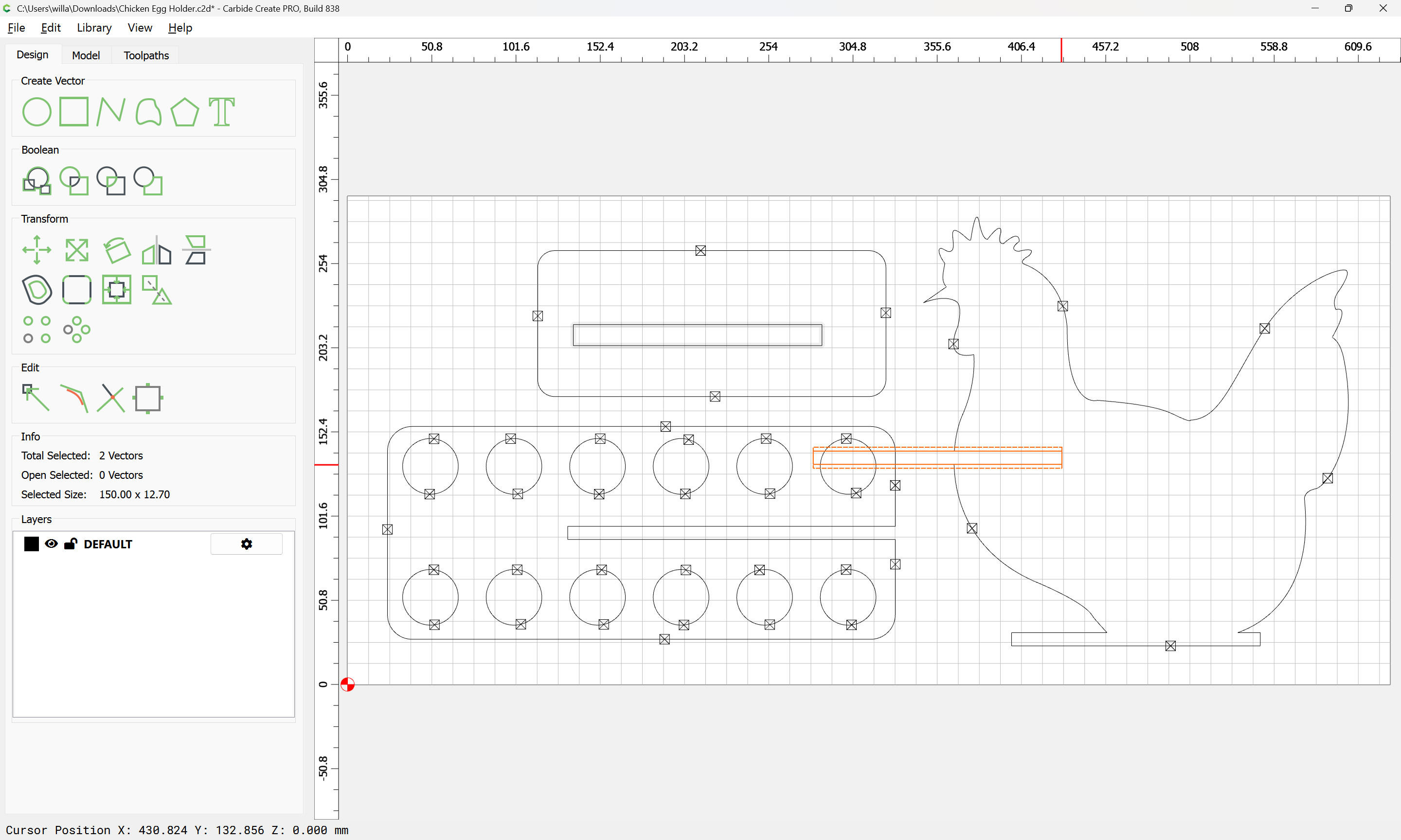
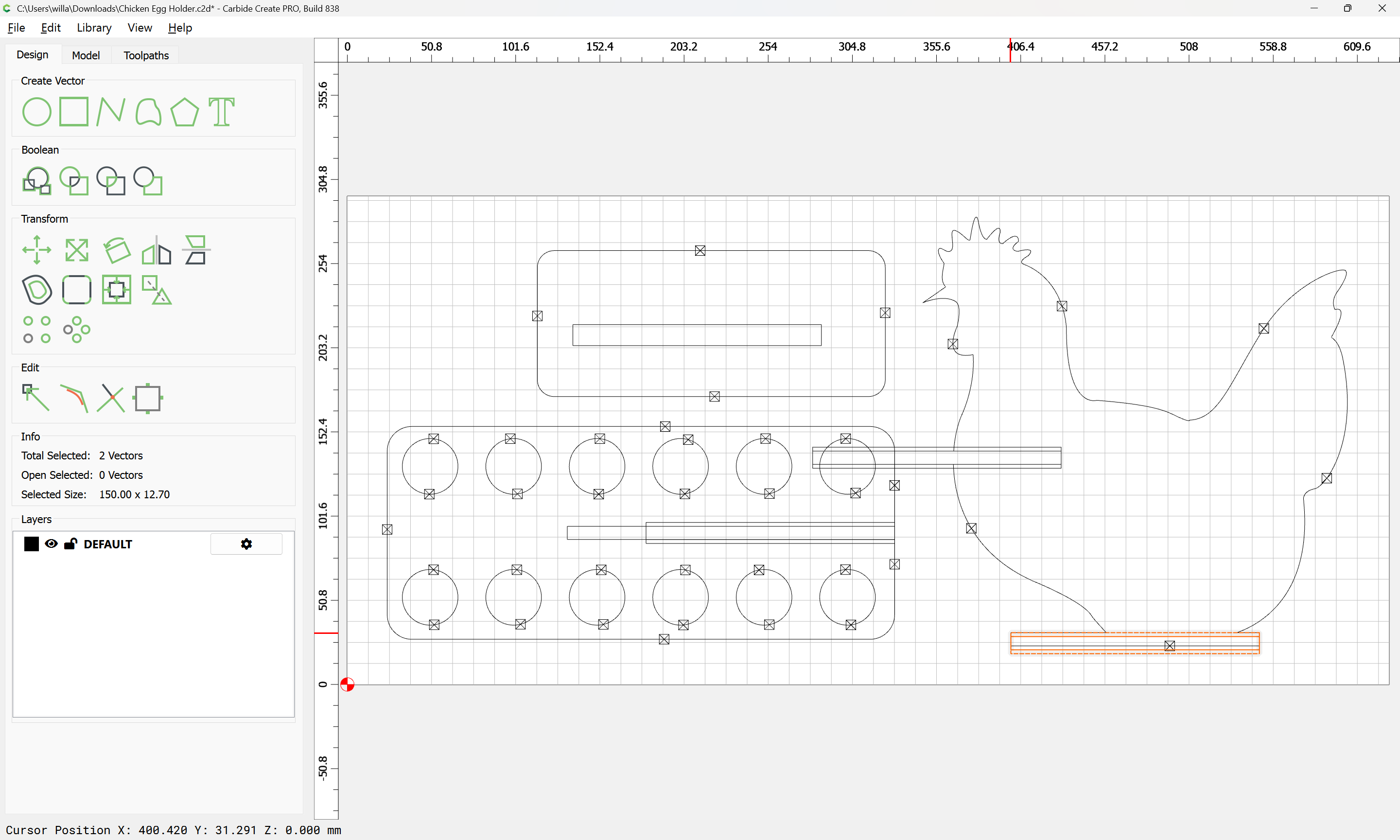
Copy-paste this construct as many times as is necessary and drag into alignment with other features:
(it will need to be resized, but this at least saves recreating it)
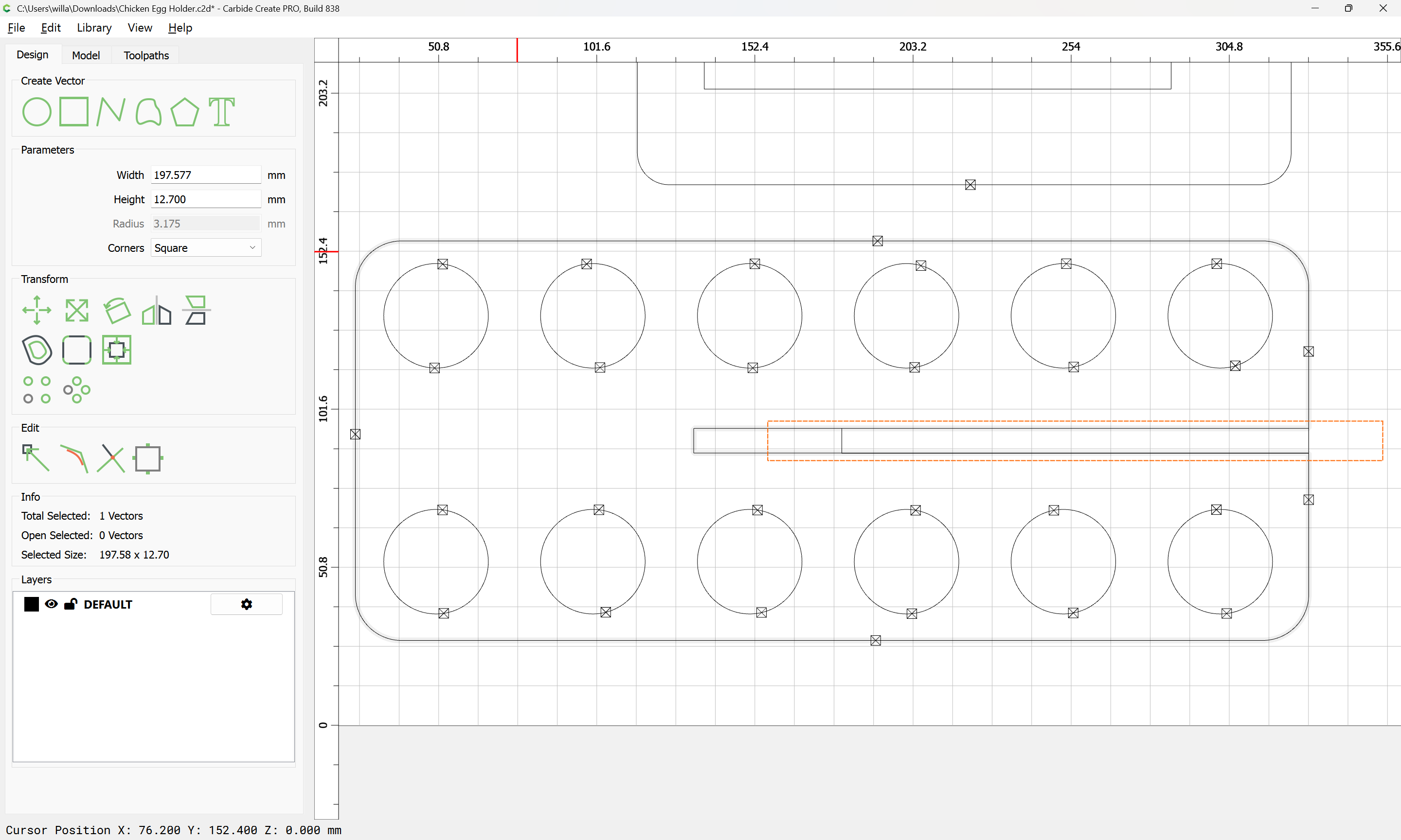
Select a rectangle which is the correct size and the corresponding geometry:
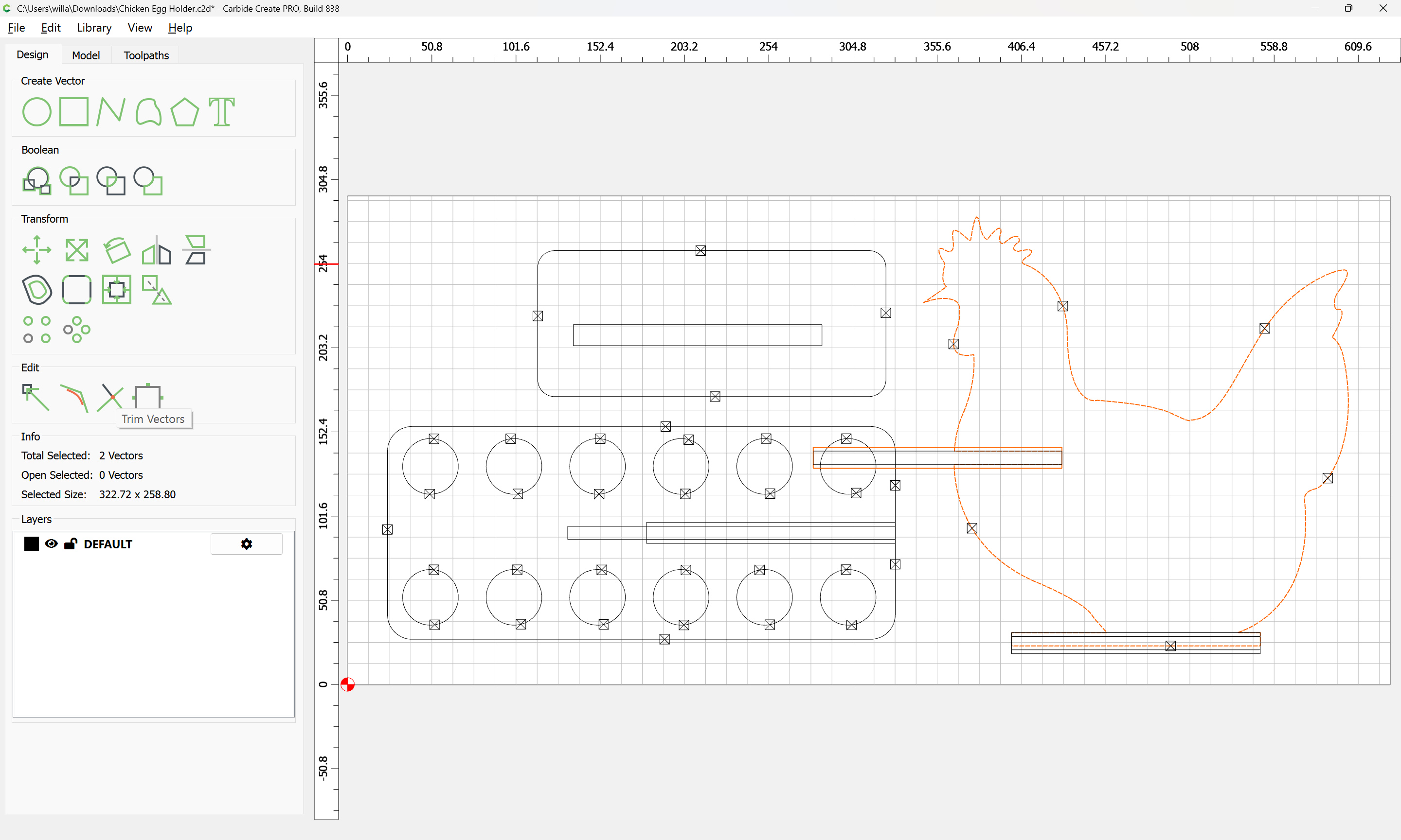
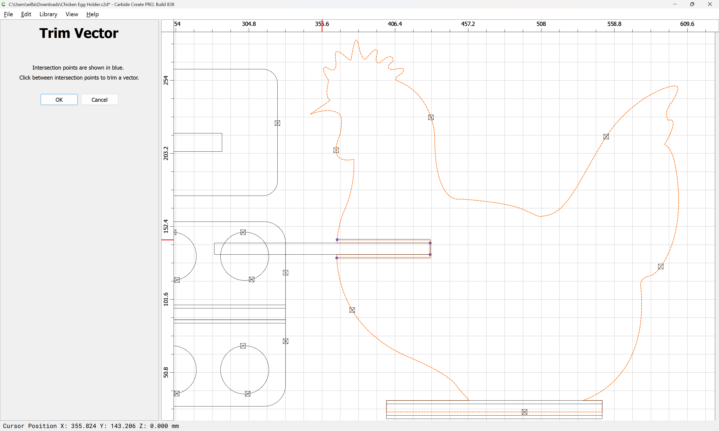
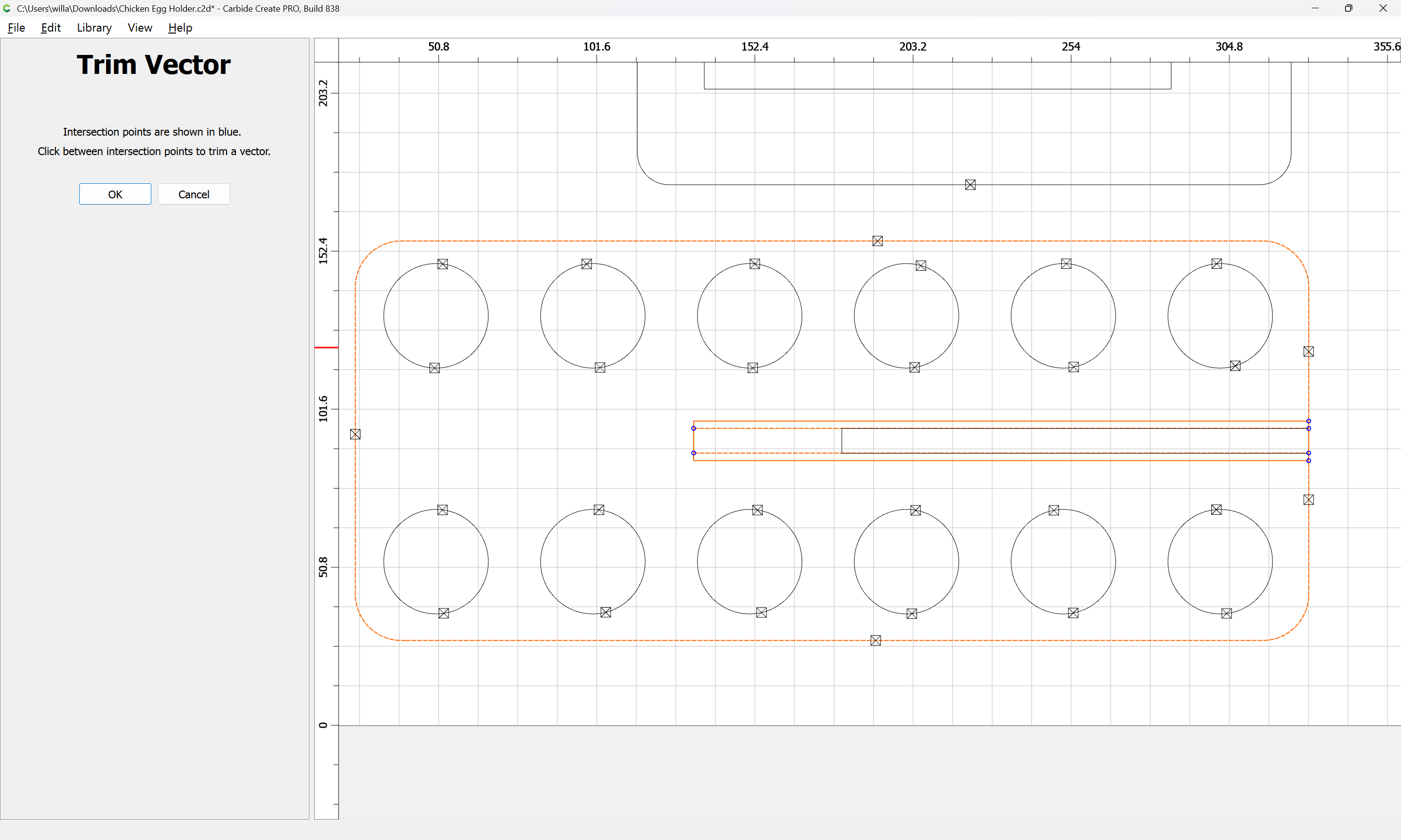
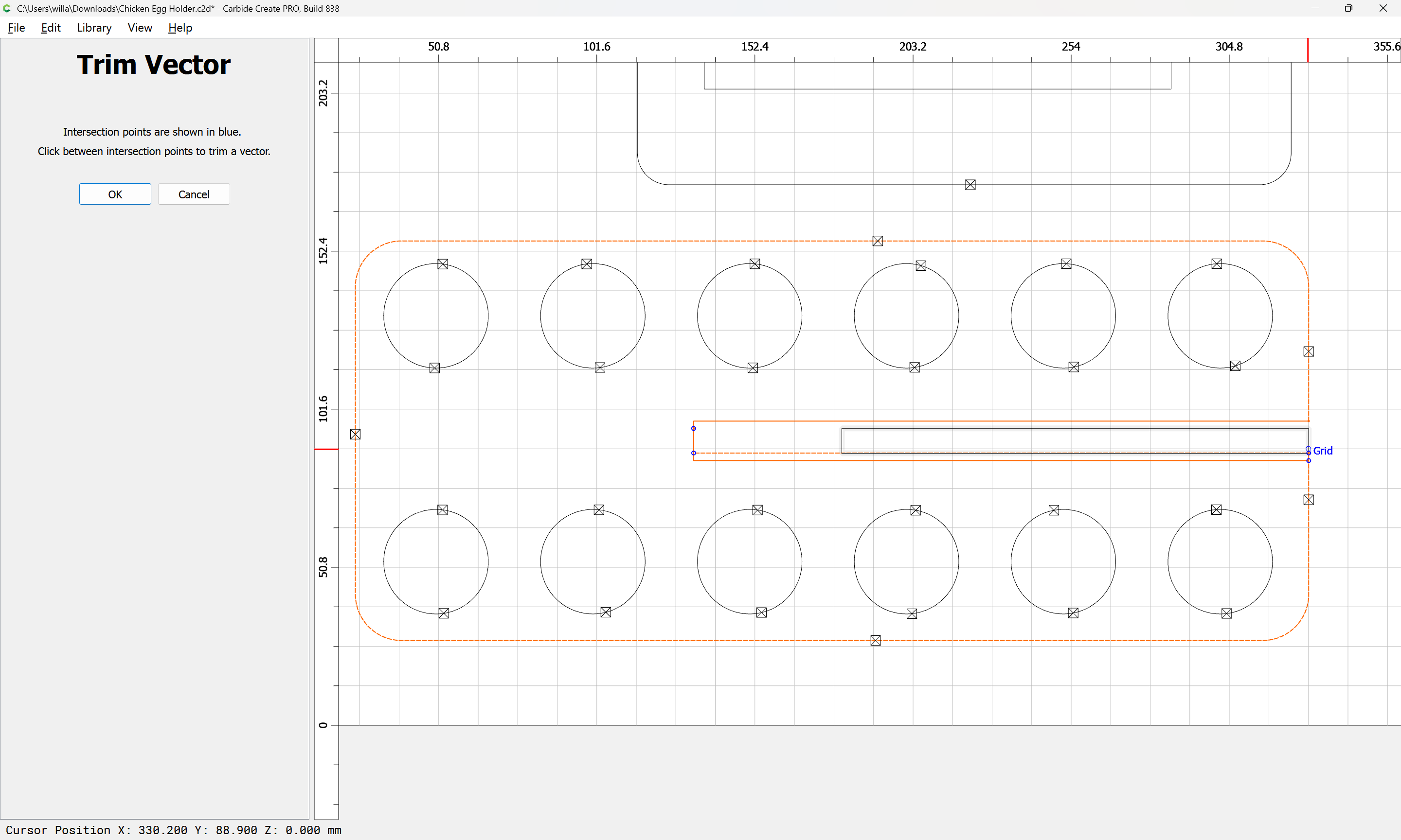
and use Trim Vectors:
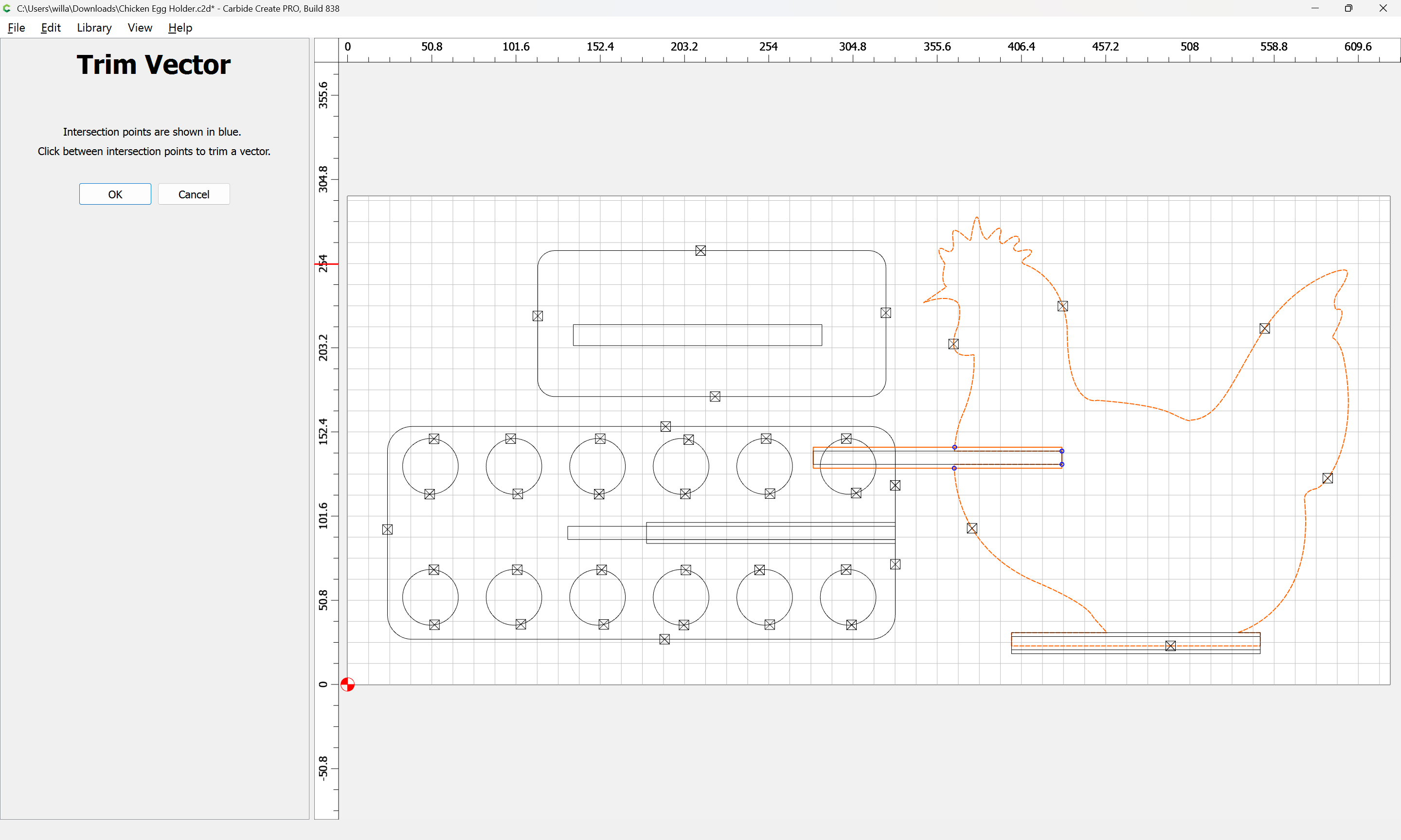
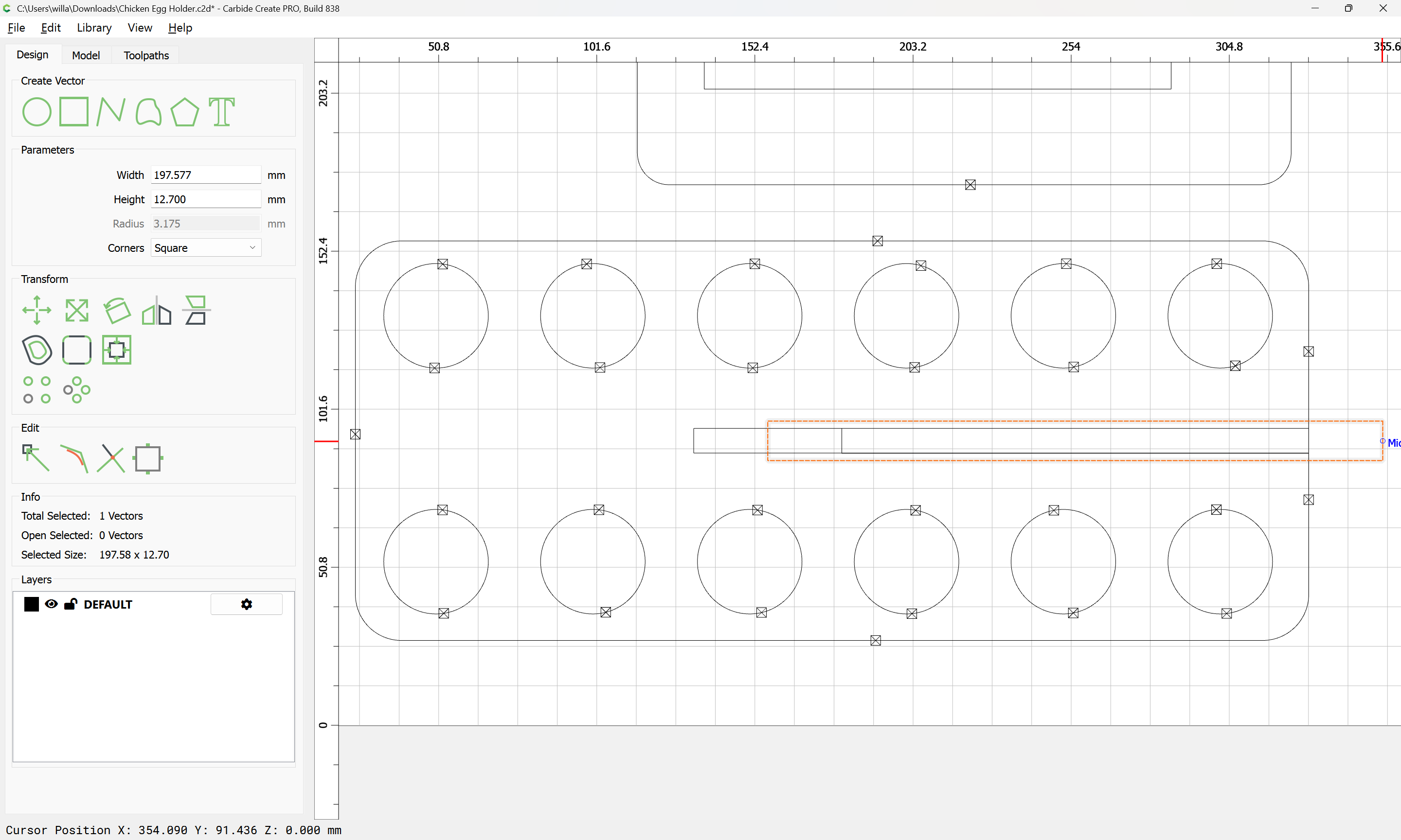
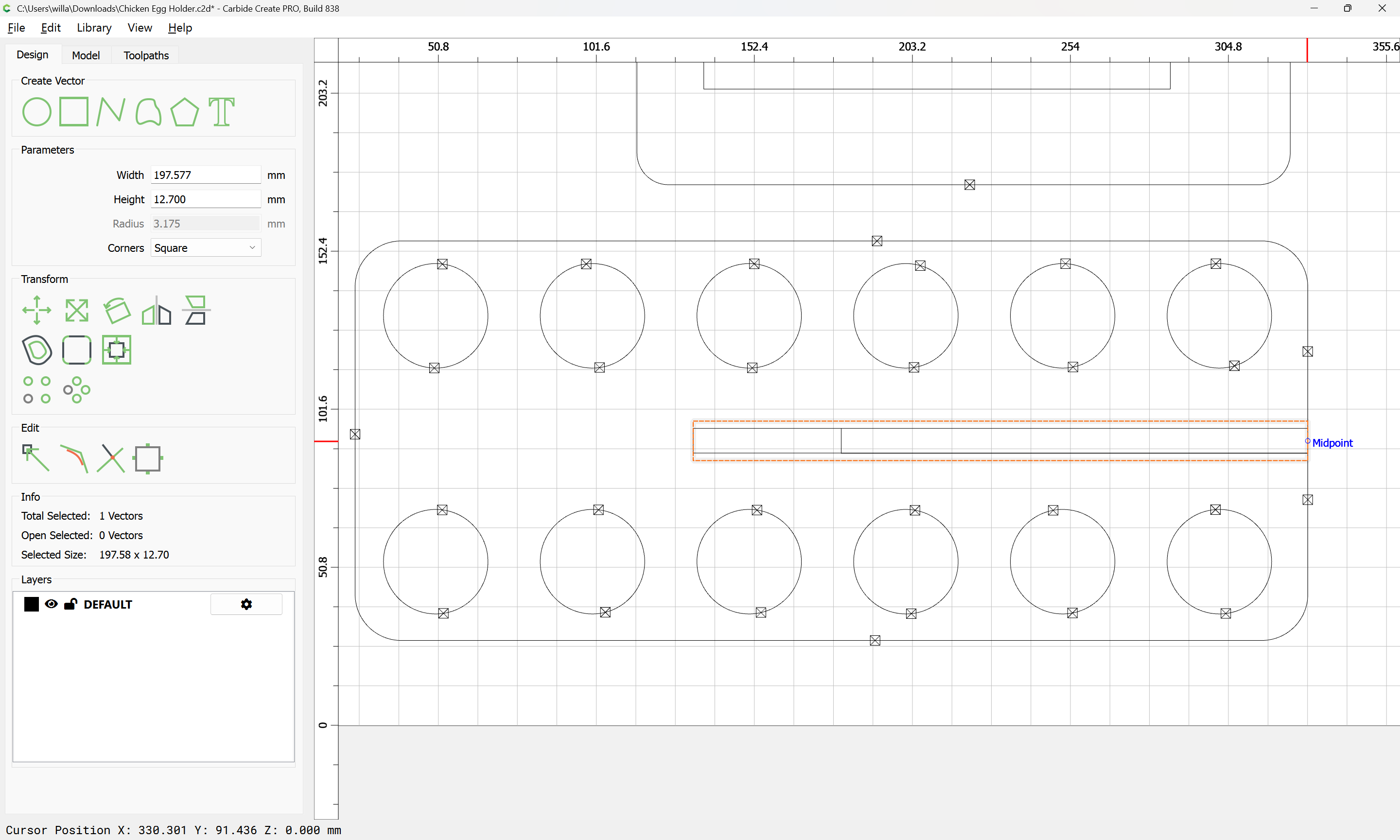
zooming in:
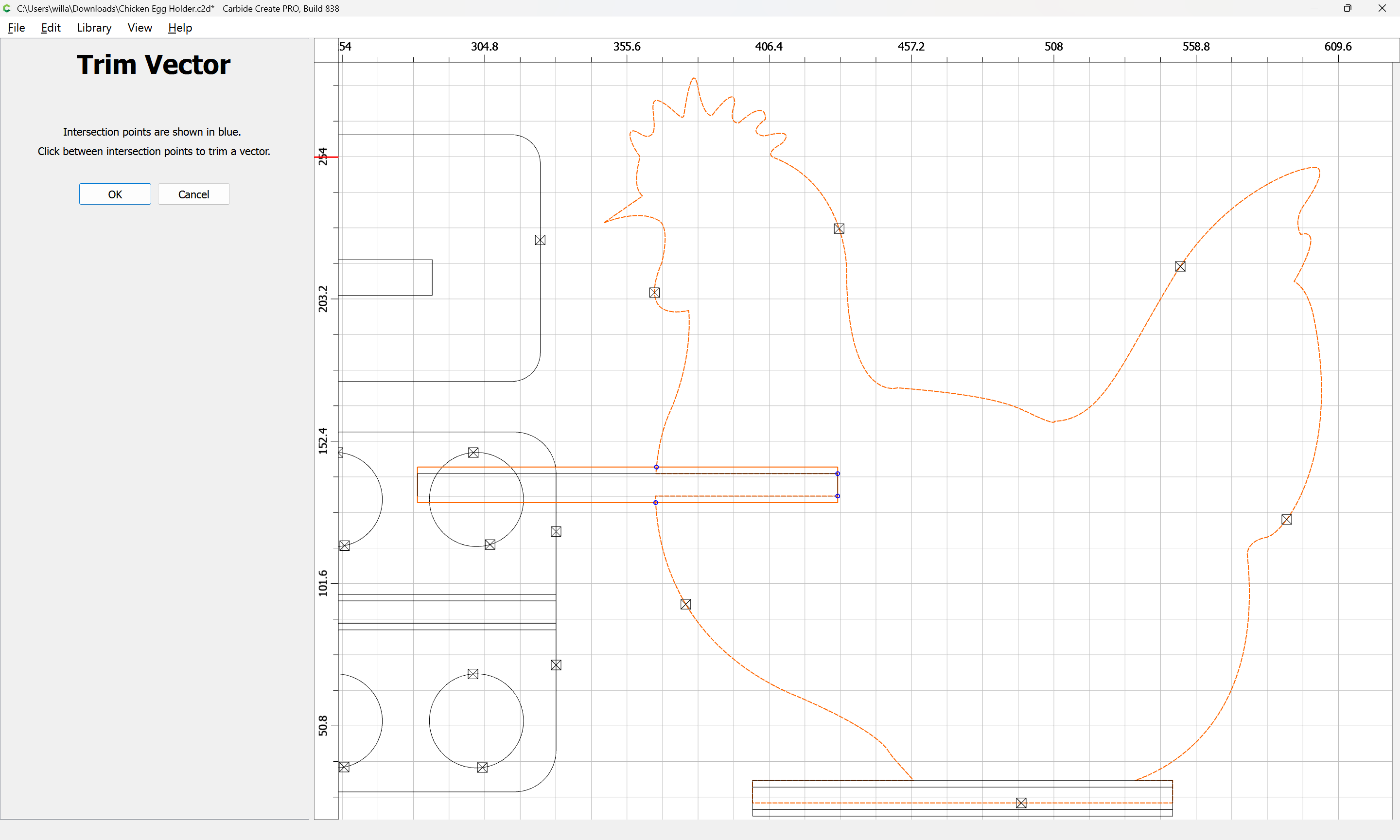
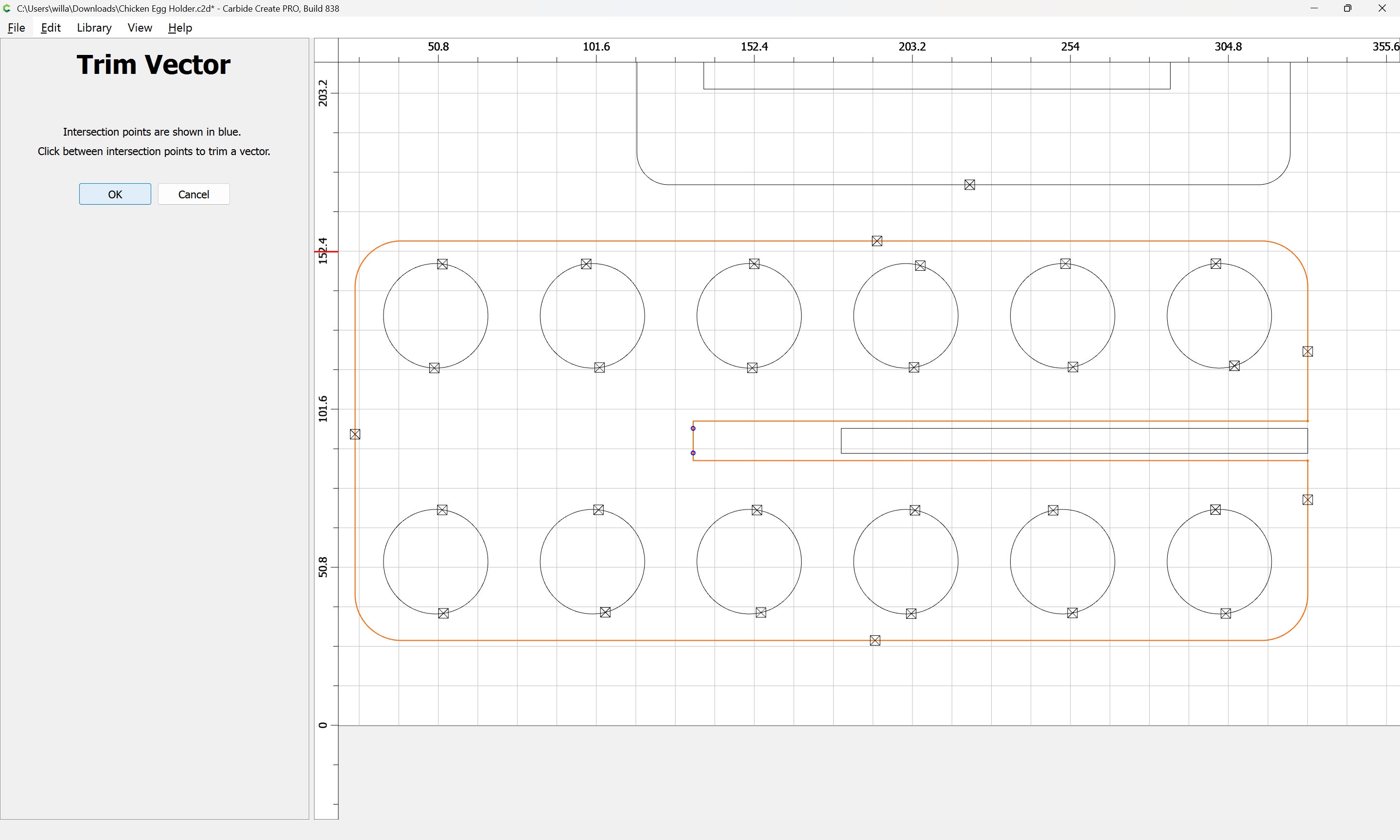
and click to remove what is not wanted:

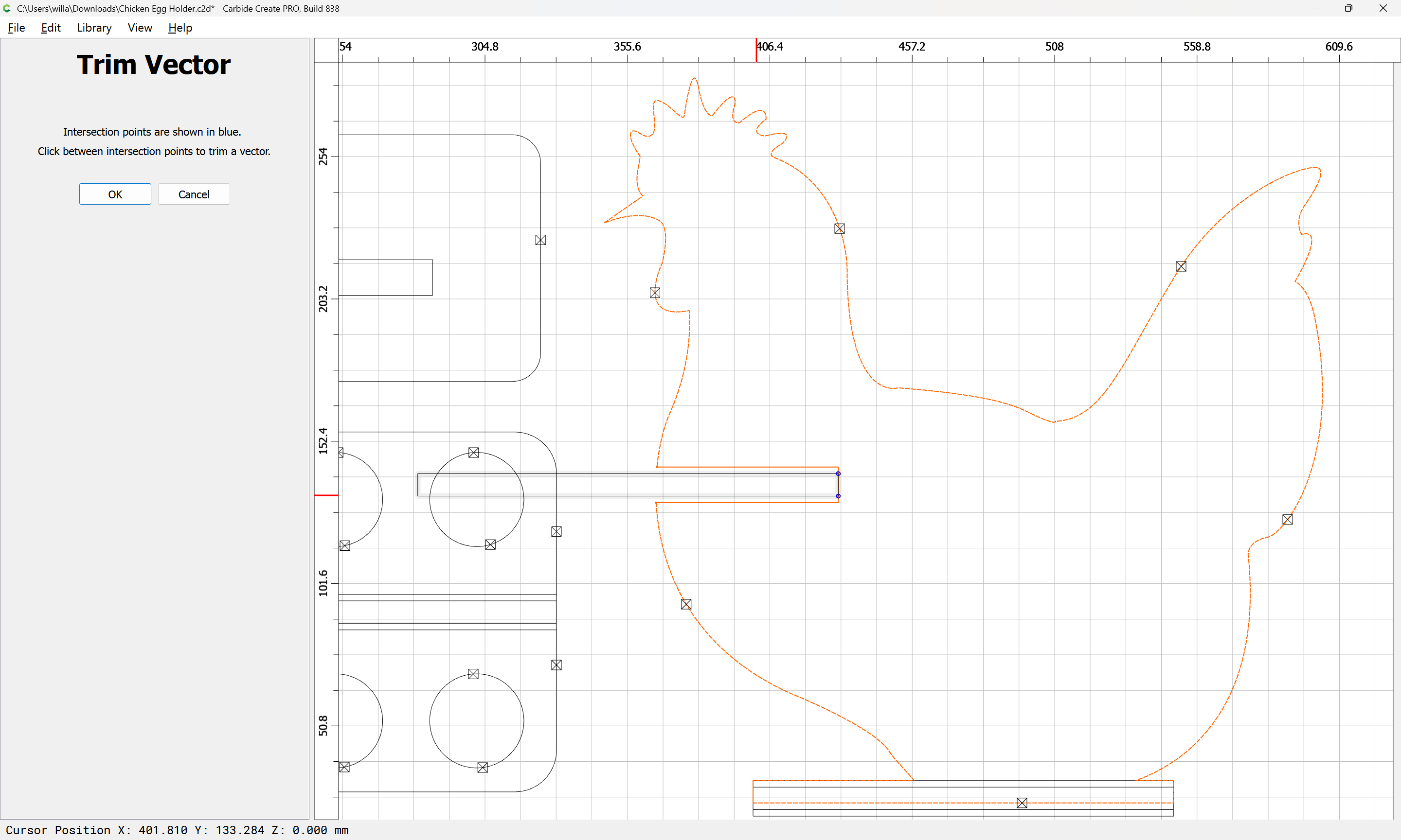
OK
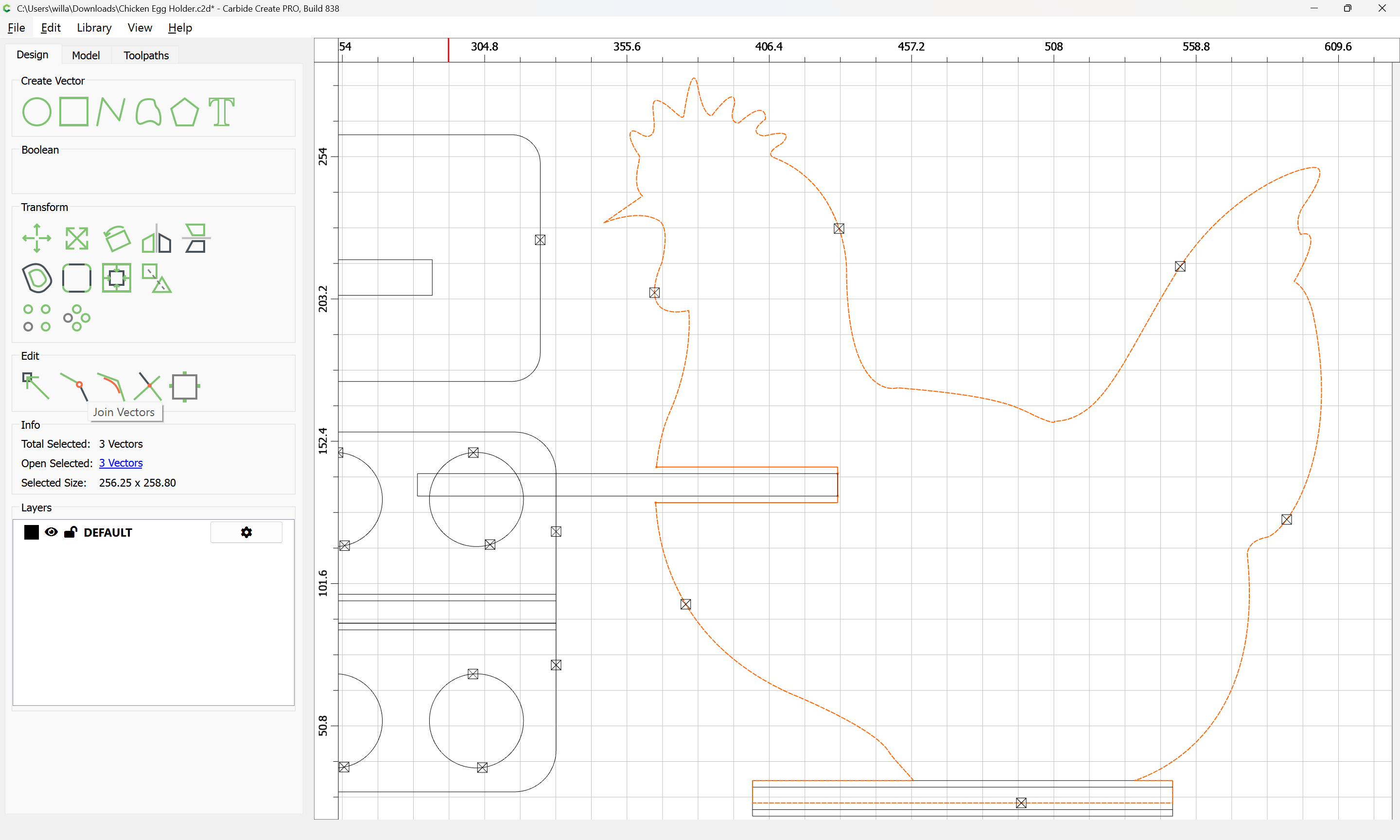
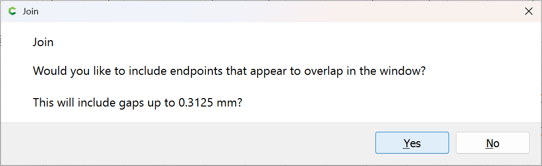
Join Vectors:
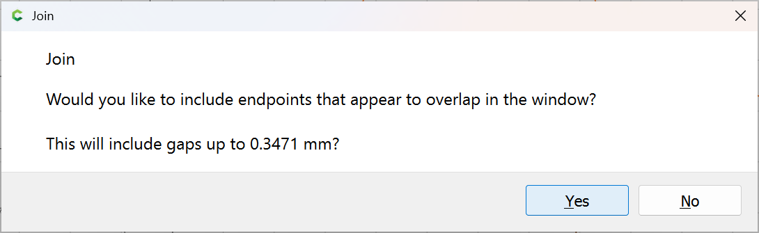
Yes
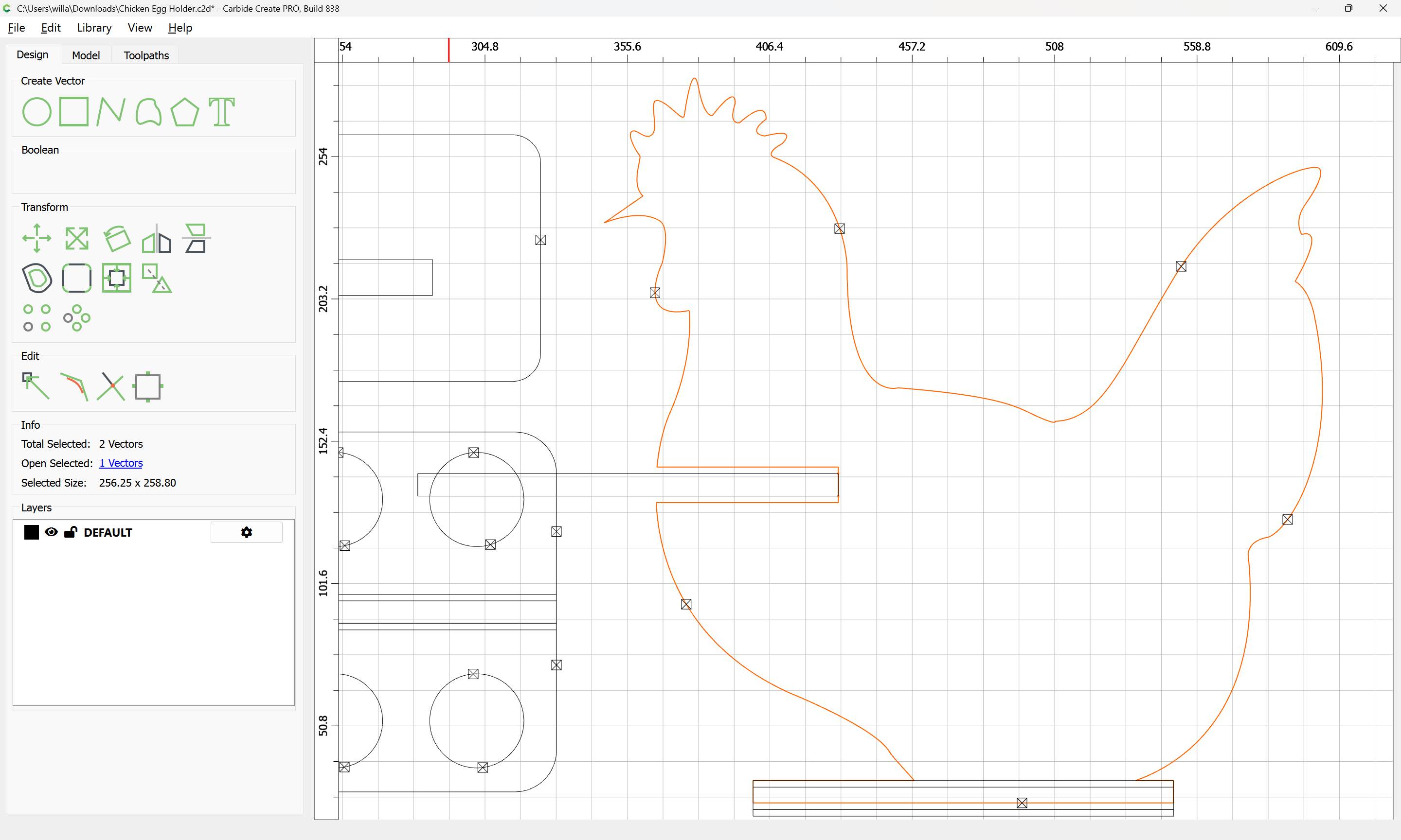
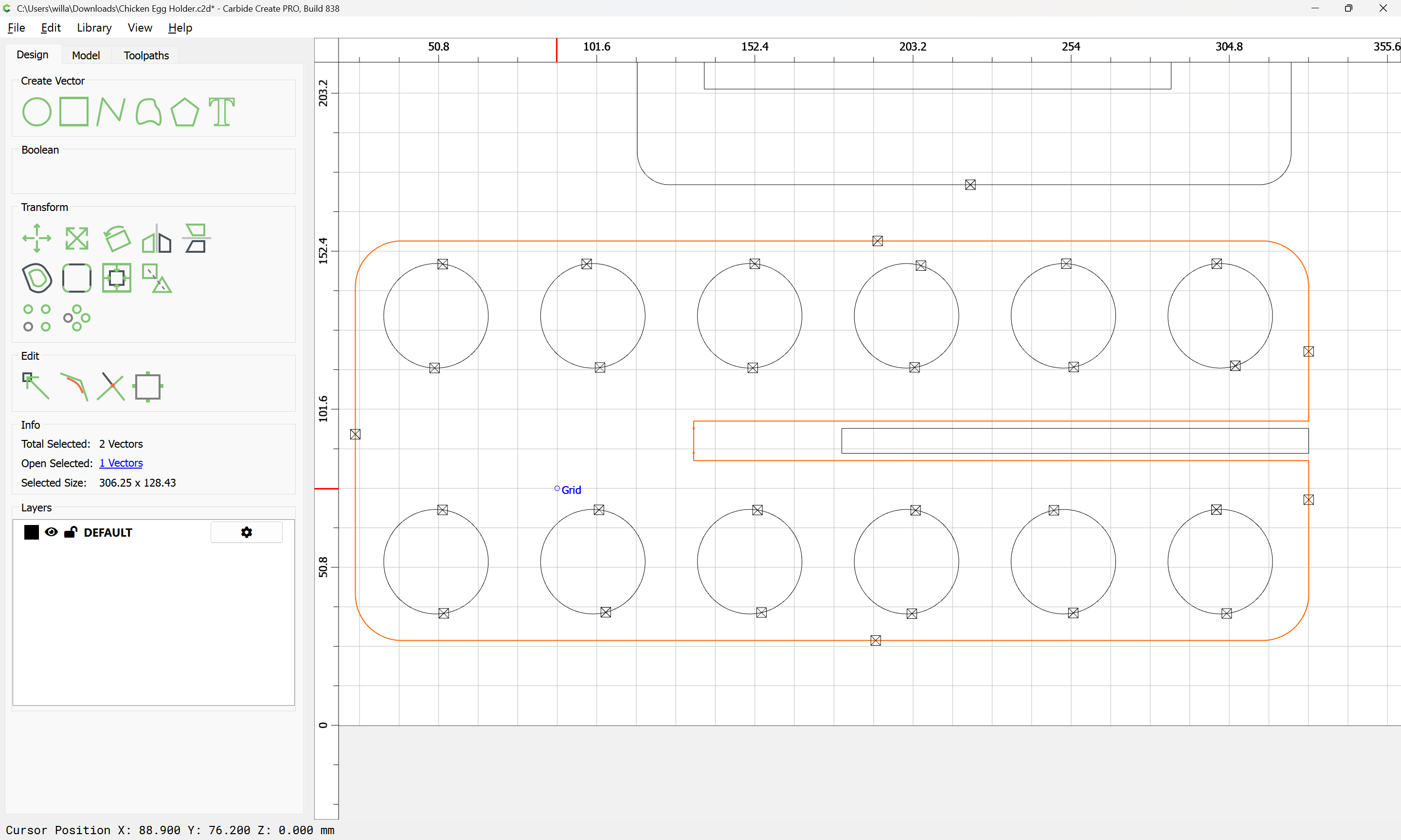
shift-click on the finished outline:

and delete the errant bit:
as well as the no longer needed construction geometry:
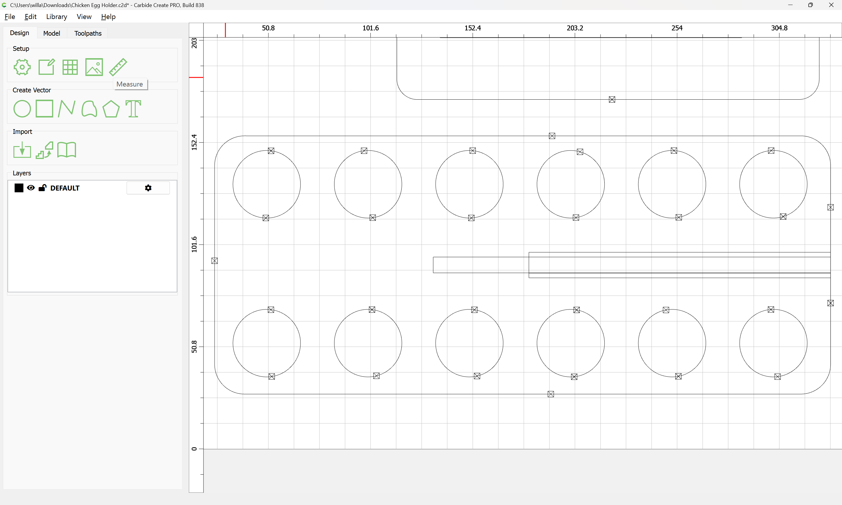
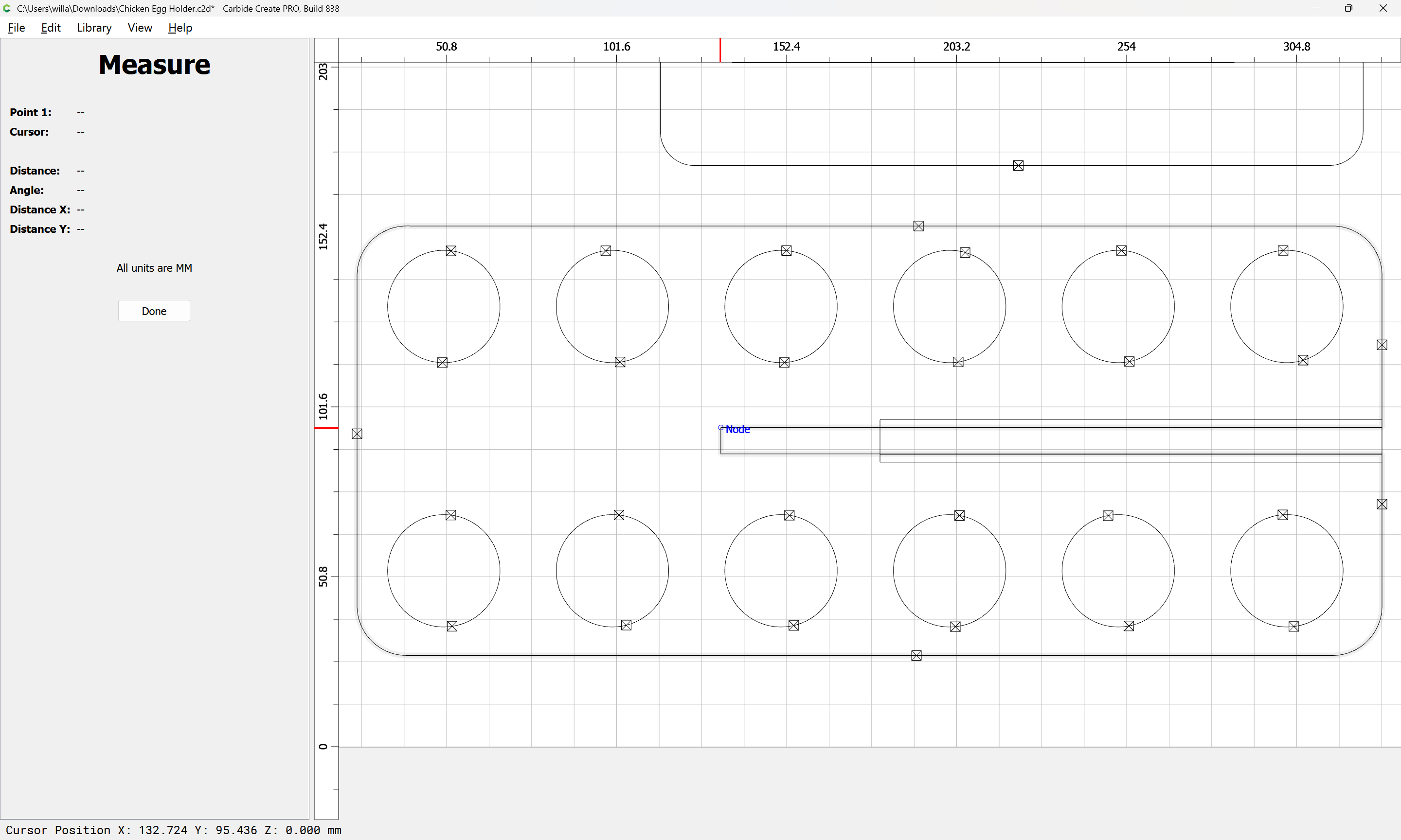
Resize the other taller rectangles by measuring:
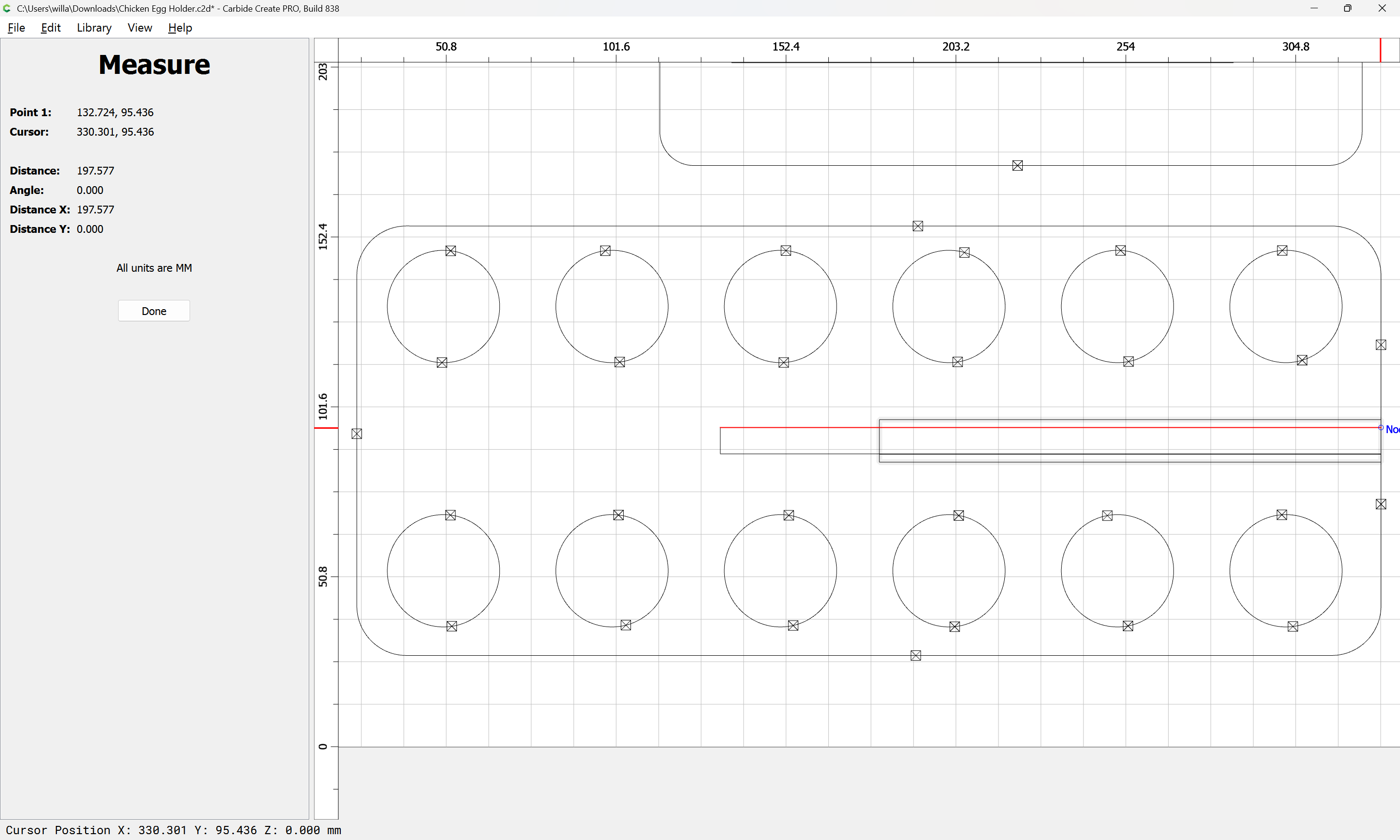
Done
Select the taller rectangle:
apply the measurement:
drag it back into registration:
Repeat the Trim Vectors operation:

OK

Join Vectors
Yes
as before shift click on the finished part:
shift-click on the no longer needed construction geometry to add it to the selection:
and delete:
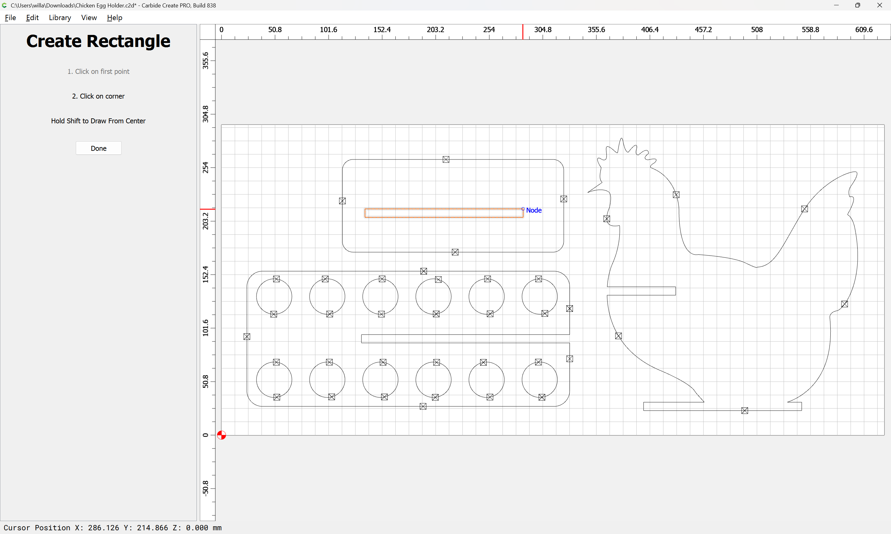
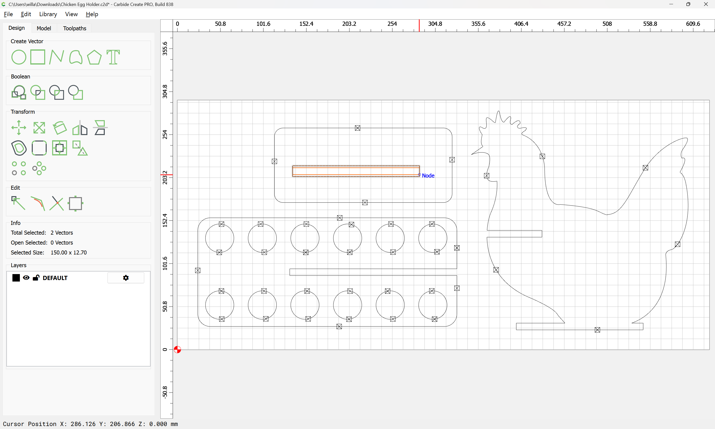
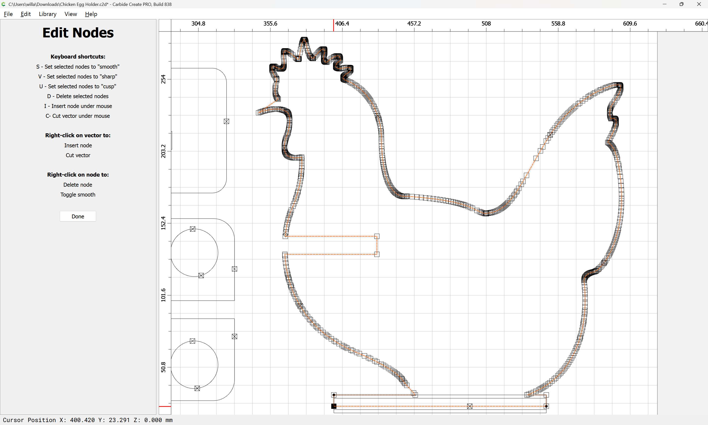
With the new snap to node feature in Node Editing it is now possible to directly modify simpler features accurately (probably this technique would have worked for the previous modification as well, but would not have worked for the chicken as readily):
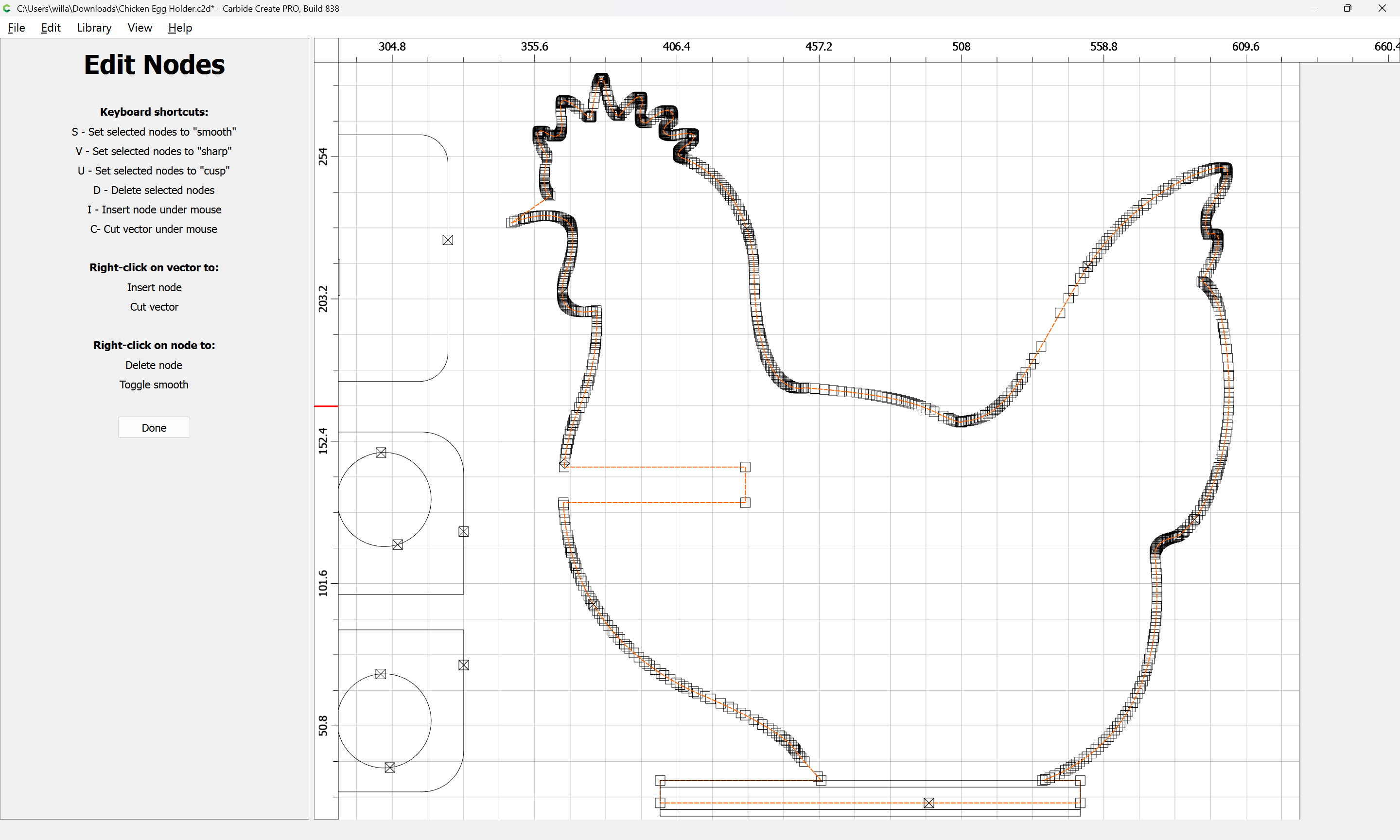
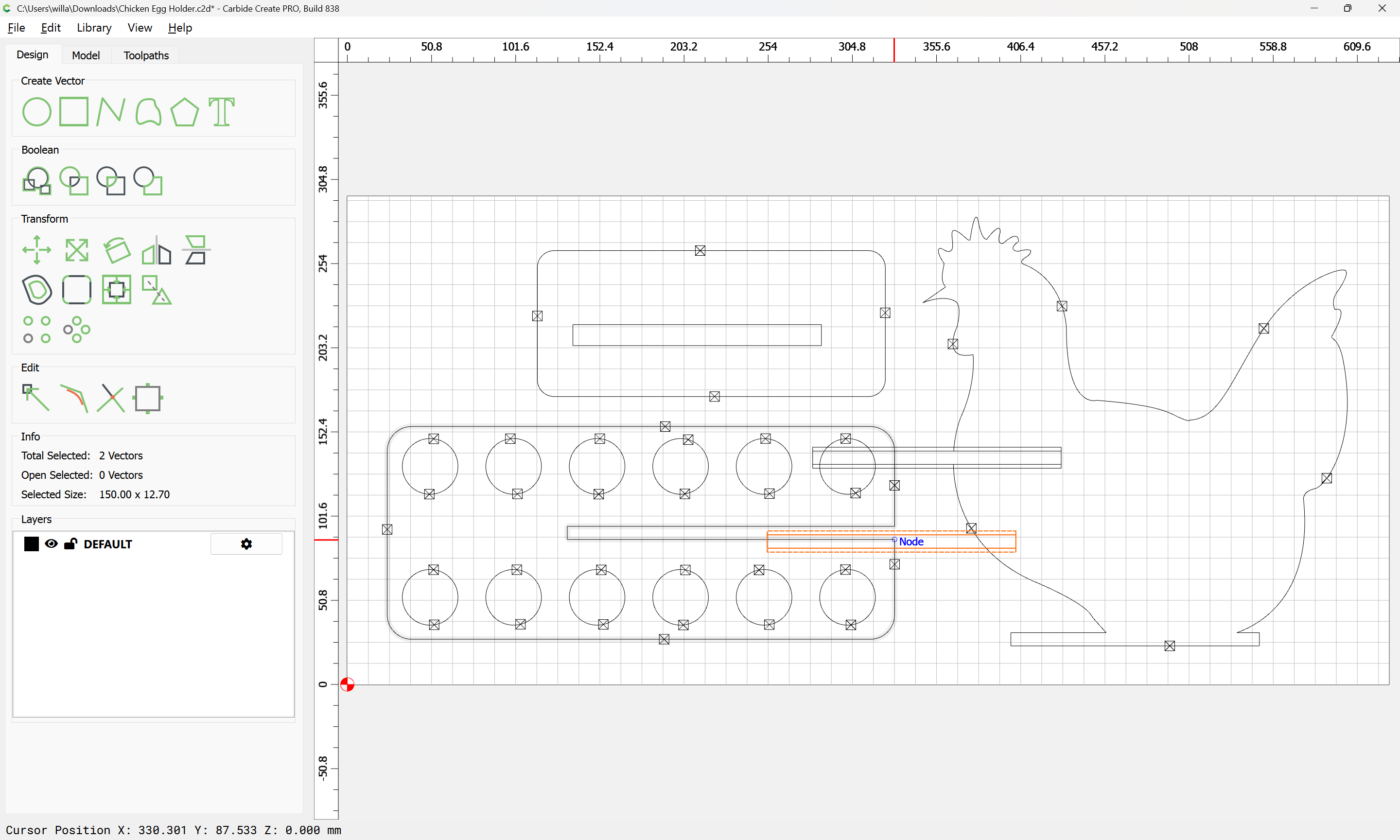
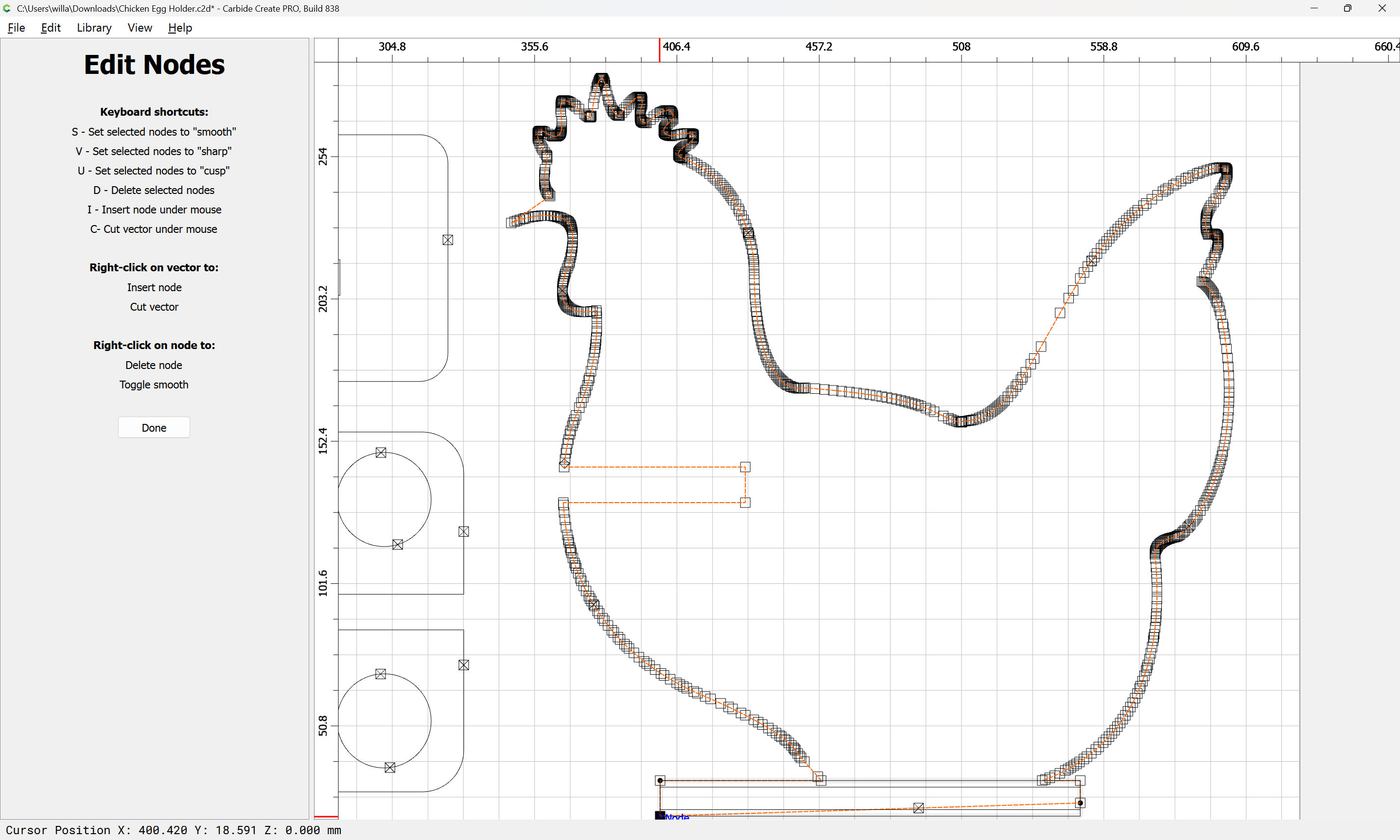
Select a node which one wishes to move:
drag it into registration with the construction geometry:
Repeat for the other:
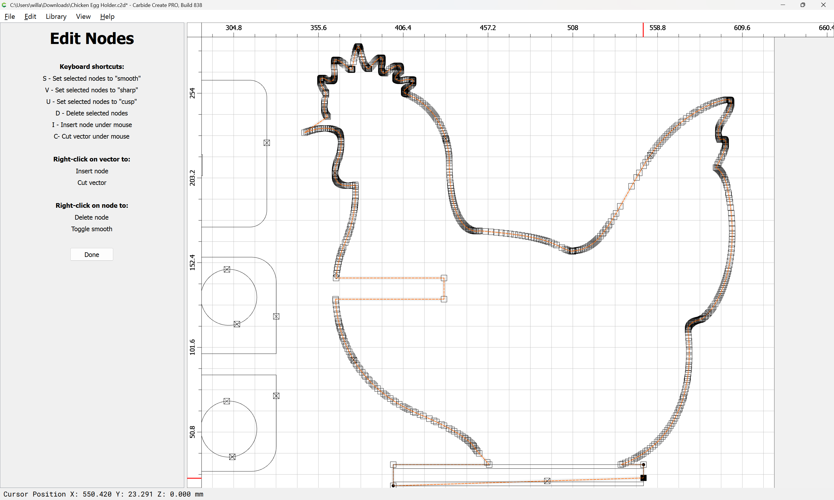
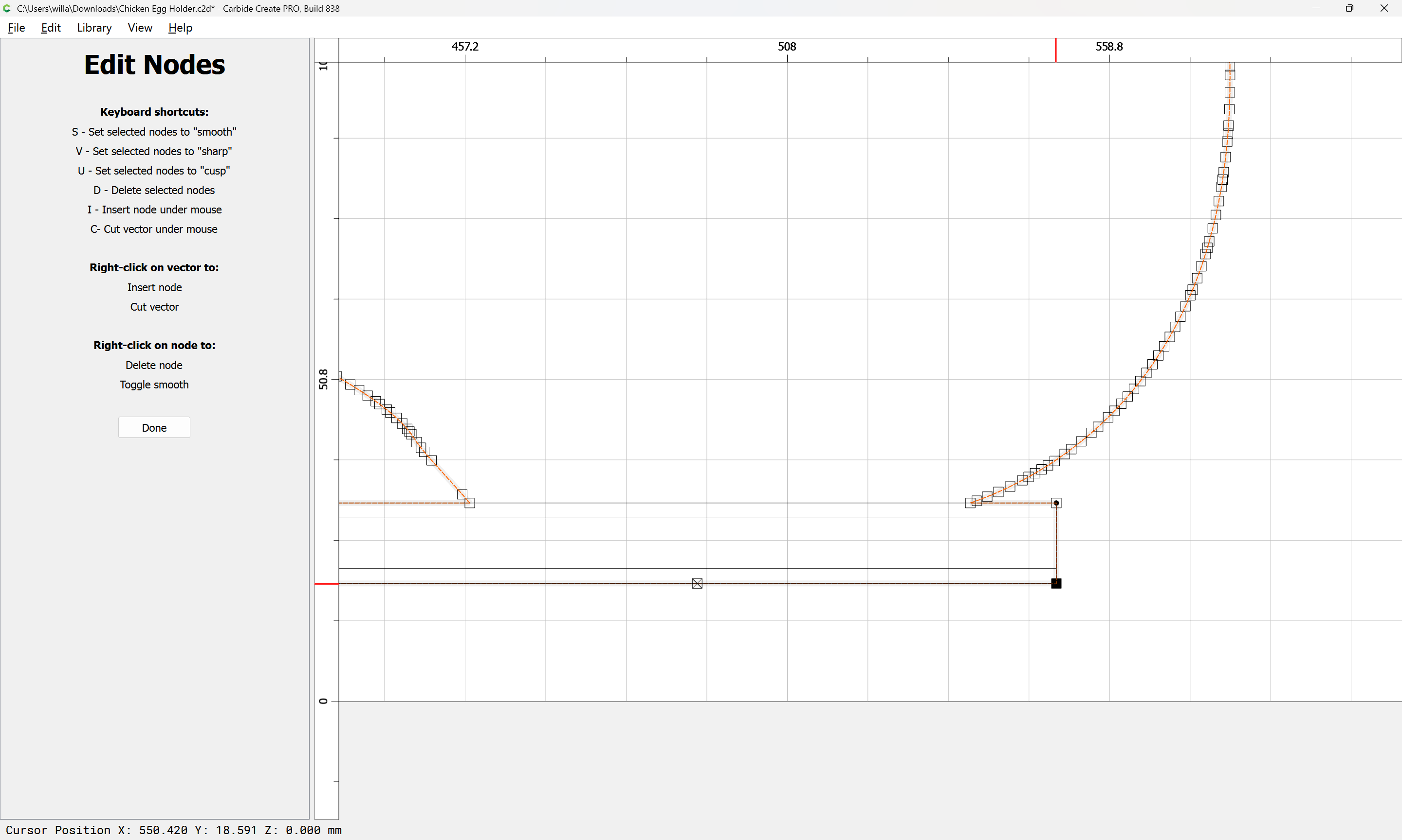
(if need be, zoom in)
Done
select and delete the construction geometry:
Reassign toolpaths as needed:

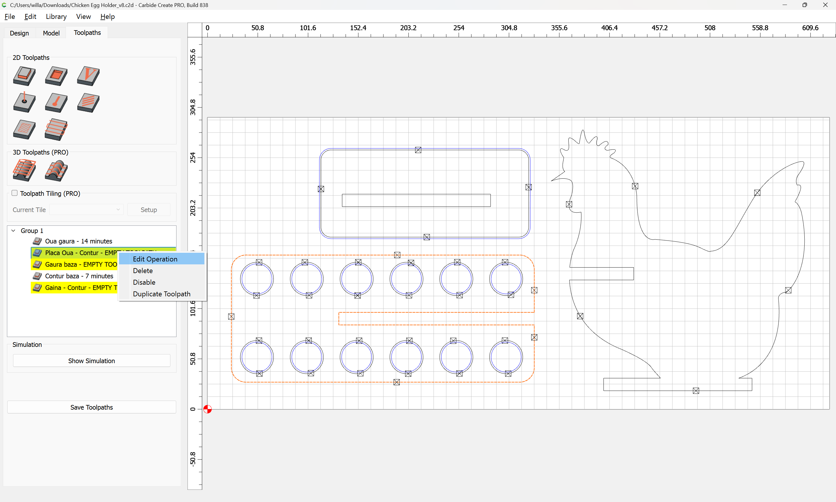
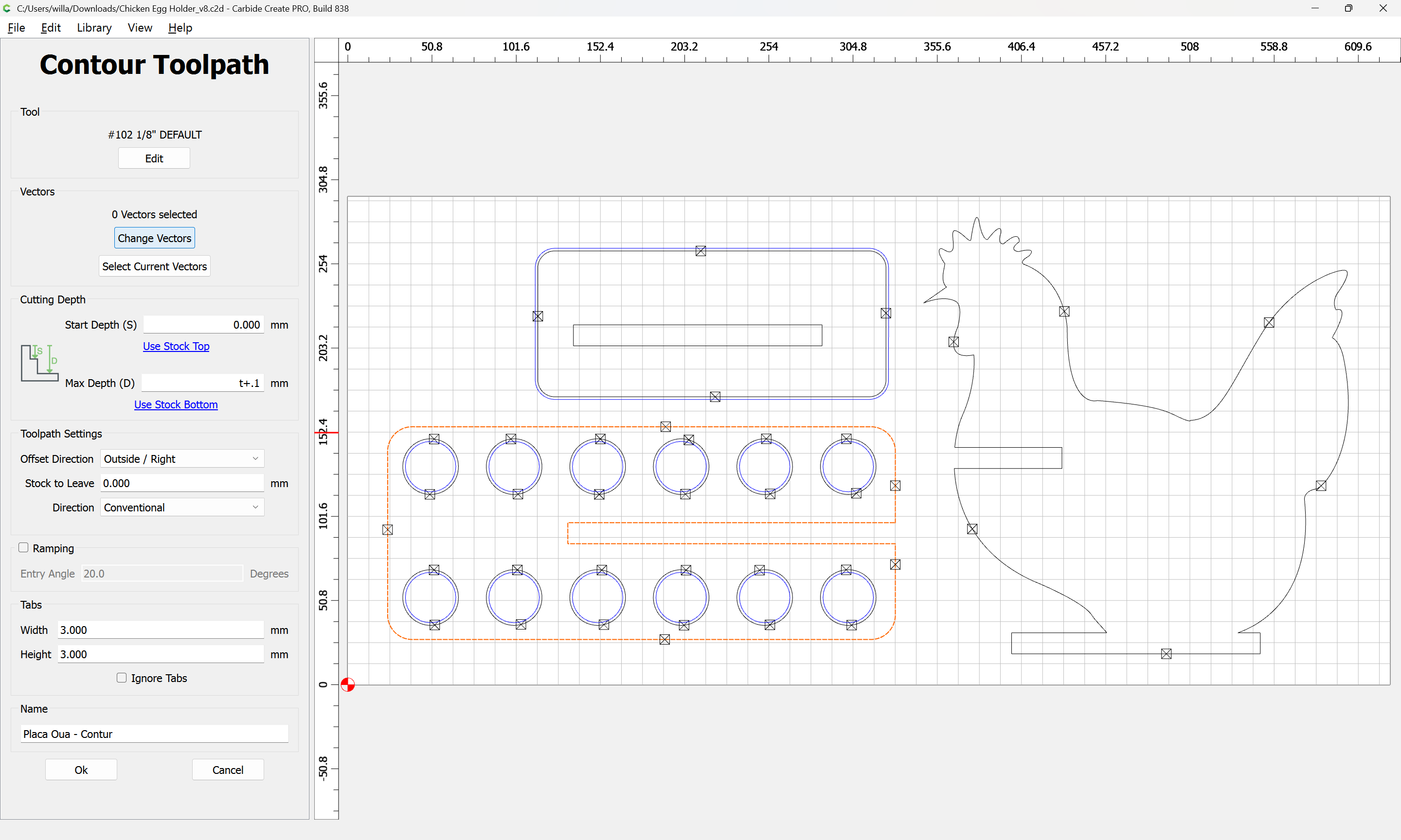
Change Vectors
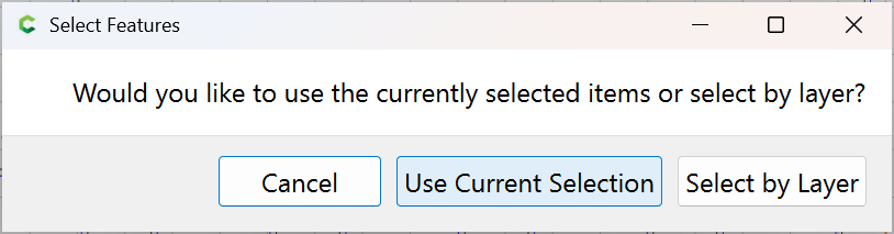
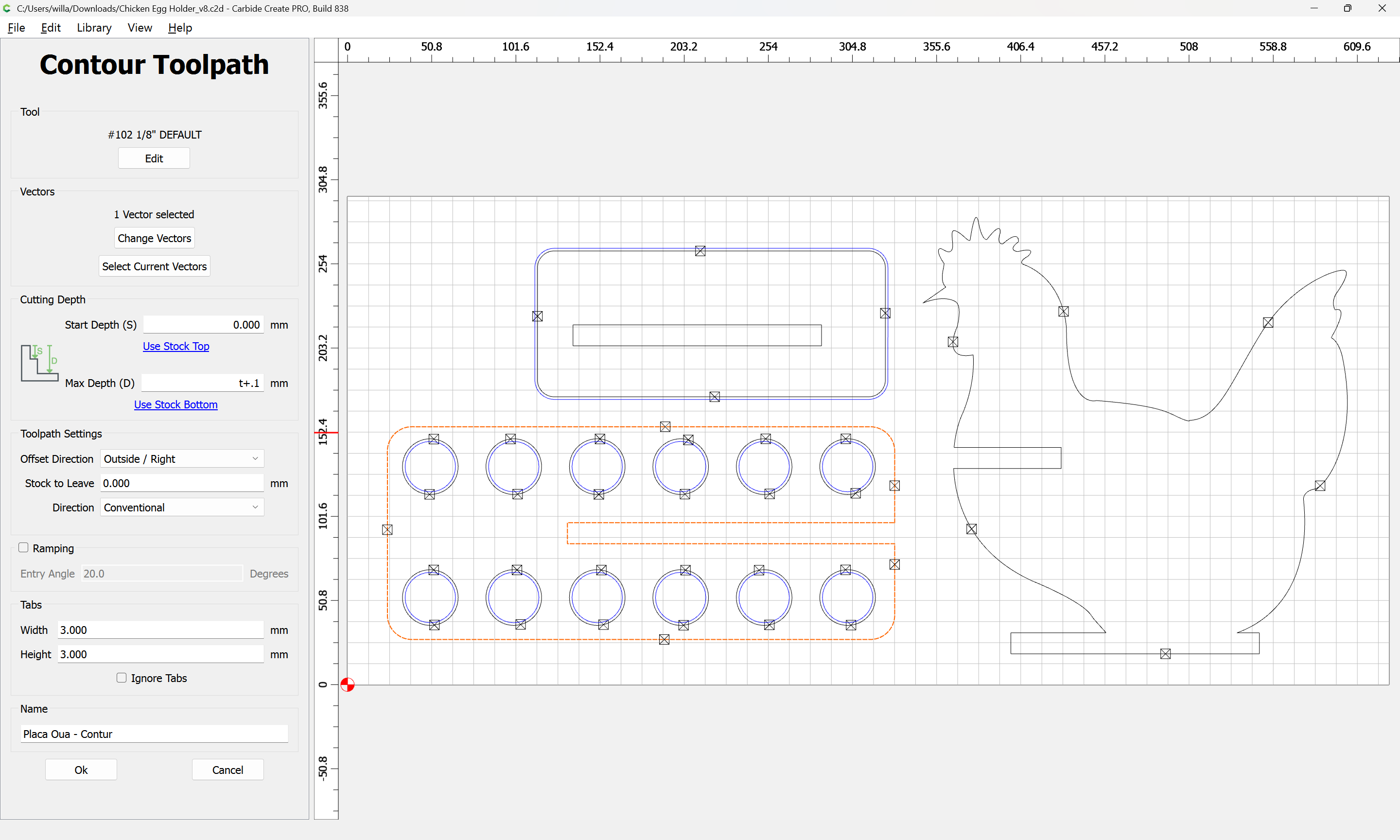
Ok
Repeat for the other elements.
Since the stock is thicker, it will be necessary to add offset geometry and cut as a pocket — where possible avoid slotting and add geometry and cut as a pocket (Making vacuum hose adapters and/or Adding geometry to cut as a pocket with a finishing pass ) and consider leaving a roughing clearance and taking a finishing pass.
Similarly, feeds and speeds should be adjusted to match the tooling used and material cut: