And He's Buying a Railway to Heaven: A Linear Guide Rail Story

So what’s the Story?!?

I don’t really do any outrageous projects that truly warrant linear guide rails, but something about the modification seemed achievable and the benefits, undeniable. I’d love to write a full blown tutorial; however, my documentation from this install has a bit too many holes. If my local buddy that just picked up an SO3 XL feels like investing in linear guide rails, I’ll be sure to do a better job at picture taking and making notes. Be warned: this is a glorified brain dump!

I have plans to install the Y-axis rails, but decided to complete the X-axis rails first so I can experience improvements in performance while milling the Y-plates.

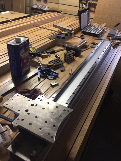
STEP 1: Fabricate the Z-Adapter Plate, Spacer Plate, and X-Axis Motor Mount/Guide Bearing Plate
Download the Files (Dan Story’s Thingiverse Post)
Make Any Desired Design Changes
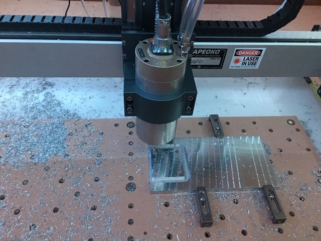
Plan Your Stock Type and Workholding Strategy

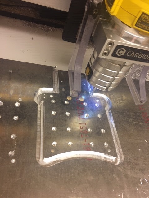
  • .375" 6061-T651 Type 200 Tooling Plate Aluminum for the Z-Adapter Plate (locally sourced from SMC Metal)
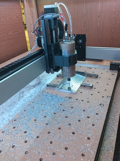
  • 5"x10" 1/2" ATP 5 Cast Aluminum for the Spacer and X-Axis Motor Mount/Guide Bearing Plates ($16.75 + shipping at the time).
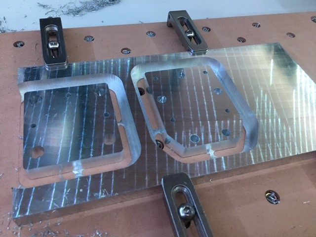
  • Oversized stock with C3D Gator Tooth clamps.

Program Toolpaths
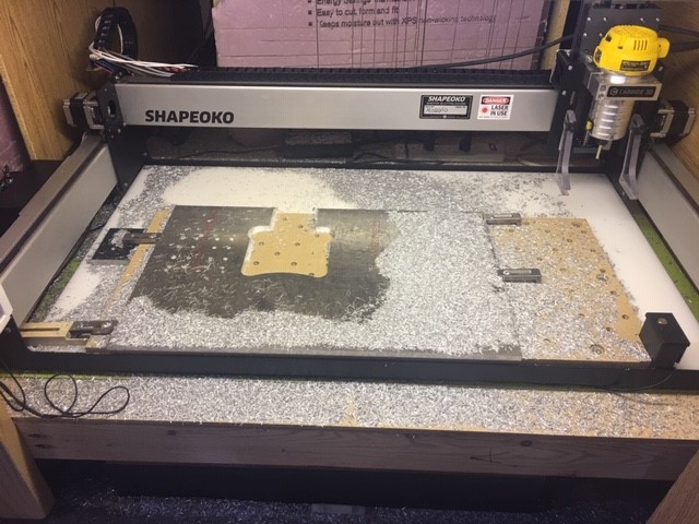
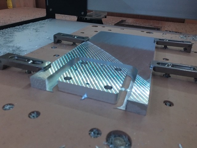
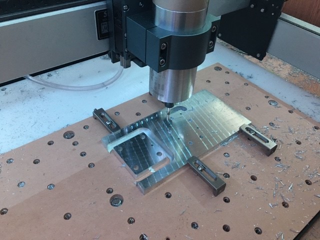
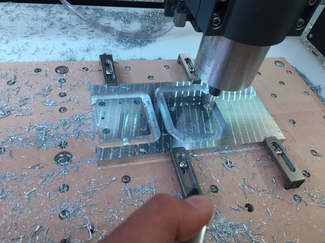
Mill Adapter, Spacer, and X-Axis Motor Mount Plates

Milled HDZ Linear Bearing Block Adapter Plate Aftermath


Milling X-Axis Motor Spacer 2 Milled X-Axis Motor Spacer
Starting to Mill X-Axis Bearing Guide Plate Contour Milling X-Axis Bearing Guide Plate Milled X-Axis Motor Spacer and Guide Bearing - Motor Mount Plate
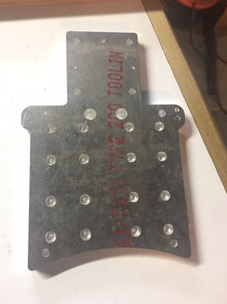
Drill and Tap Threaded Holes in Plates

STEP 2: Install the Linear Guide Rails
Remove X-Axis Extrusion
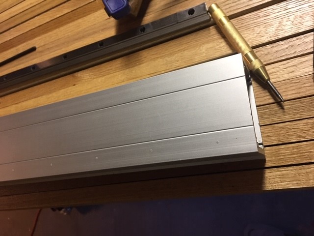
Mark Linear Rail-One Mounting Holes

Transfer punched X-Axis Extrusion
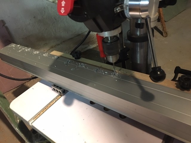
Drill and Tap Linear Rail-One Mounting Holes
Drilling First Row of Linear Rail Mounting Holes
Install Linear Rail-One

Mark Linear Rail-Two
Drill and Tap Linear Rail-Two Mounting Holes
Install Linear Rail-Two
Install Bearing Blocks
Install Adapter Plate

Re-install X-Axis Extrusion
X-Axis Extrusion with Rails and Adapter Plate Installed

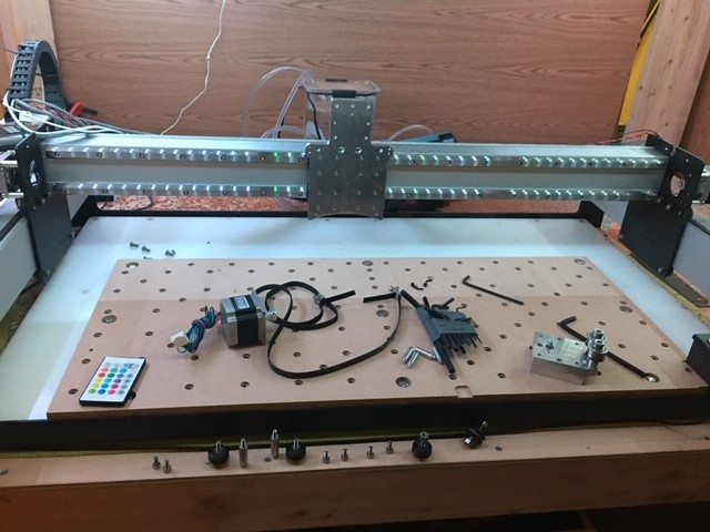
STEP 3: Install the Z-Axis, Spacer, and Motor Mount/Guide Bearing Plate
X-Axis Linear Rails Finished Install
Installing Spacer and Motor Mount Plates


Looking at the steps and pictures above, it makes it seem like everything was easy and smooth sailing, but there were a few bumps and bruises along the way. All-in-all, a pretty good experience.

Fabricating The Plates

Installing the Linear Guide Rails
I didn’t really have any issues here, but wanted to drop a bunch of notes for those interested in the details.

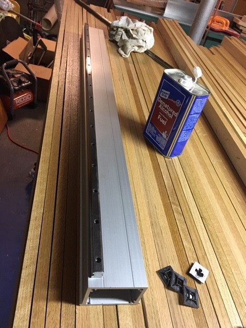
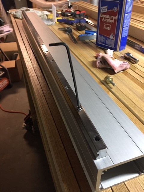
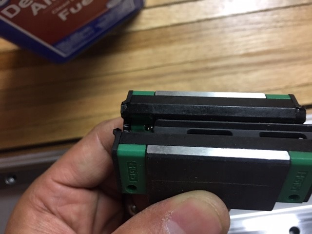
  • I ordered 1500mm rails (cheaper and readily available at the time $75 for two rails and four bearing blocks - eBay) and had them cut to size via surface grinding zip wheel and Bridgeport mill.
    Surface Grinding Ends of Linear Rail

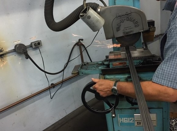
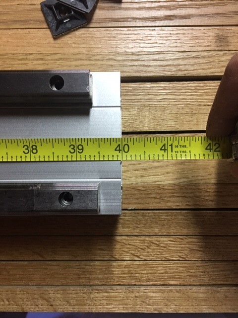
  • I chose a length of 39 inches, but I think you could get away with avoiding any cutting by buying the 1000mm standard rail length. Caution: If you flipped your OEM X-axis end plates you have to pay attention and design around the PEM nuts and M8 bearing guide SHCS.

    Bearing Block Bearing Gap
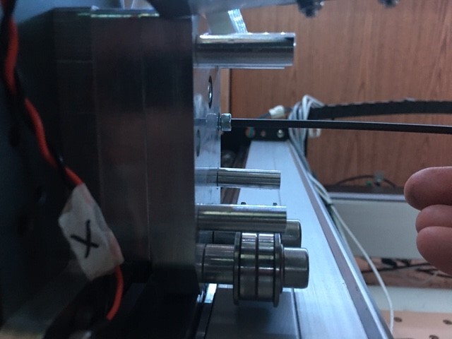
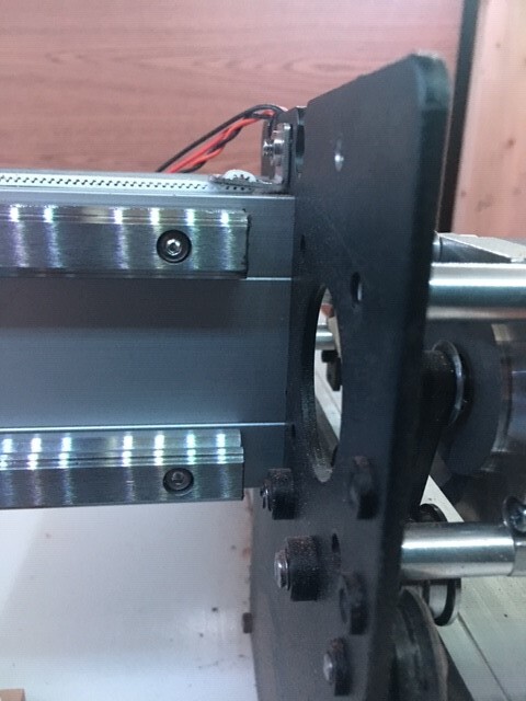
  • I rotated the X-axis extrusion to have the v-wheel rails face the back side of the machine mainly so I didn’t have to remove my stickers, but it also made it easy to register off of a flat edge.
  • I used F-style and quick-grip clamps to secure 1-2-3 blocks to the extrusion as a datum then assembled the necessary gage block stack heights to space the linear rails accordingly. I bought the Wen steel gage block set ($95 at the time) specifically for this project.
    **TIP: It can be difficult to assemble the same gage block stack heights because you have to use different combinations for each stack, so I employed my feeler gage set in tandem with the blocks to help me achieve the necessary spacing - they’re cheap and handy.
    ***TIP: If you are willing to modify Dan’s Adapter Plate’s bearing block hole spacing, you could install the linear guide rails using @BartK’s method of installing the bearing blocks on the rails and registering them against 1-2-3 blocks - this would effectively circumvent the use of gage blocks/spacers. SO3 on steroids - build log
  • I wholeheartedly nominate the Pittsburgh transfer punch set ($10.99) as being one of Harbor Freights’ best buys. Transfer punching the holes and using a drill press fence were key to keeping the mounting holes positioned in a straight line.
  • Rail-two mounting holes were marked after installing rail one then registering three equal gage block stacks across the length according to the designed spacing which prioritizes parallelism.

Mounting
Relatively straight forward, but I think the million dollar question here is… “what can I re-use from my existing setup (what hardware do I really need to buy)?”

  • (16) M4x10mm for installing the Z-Adapter Plate to the bearing blocks.
  • (3) M4x25mm for installing the X-Motor Mount Plate through the Spacer and into the Z-Adapter Plate.
  • (36) M4x16mm for installing the linear guide rails to the extrusion. NOTE: YMMV depending on rail length or where you decide to cut your rails.
  • (6) M5x14mm for installing the Z-Adapter Plate to the HDZ. NOTE A: I used M5x14mm screws in the preexisting stepper motor holes as well as the top v-wheel hole locations; Dan suggested (4) M5x14mm for the old stepper motor holes and (4) M5x20mm for the old v-wheel holes in his Thingiverse description. NOTE B: I used button head screws because I plan on using the lower profile head in the Y-axis rail install. If you choose to use button head screws, the clearance holes in the Spacer Plate has to be enlarged.
    ****TIP: I reused the M5 SHCS with the HD eccentric nuts for the two bottom old v-wheel locations - be sure to use the bearing shim/washer underneath the head of the SHCS to prevent bottoming out the screw.
  • The motor spacers/M5 SHCS, M8 bearing guides, and items not specifically mentioned… are reused.
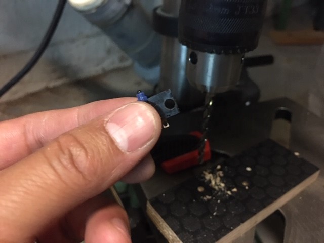
    Caution: Those that are using the mechanical homing switches, I assumed that the mounting holes on the Z-Adapter Plate bumpers would allow me to use the existing M3 SHCS and nylon nut. It may have been a machining mistake that I did; however, the holes are too close to the back plate of the HDZ so it won’t allow a screw to pass through the hole. I had cleared the holes too big to tap the hole for an M3 SHCS, but fortunately the hole was large enough that I could tap an M4 thread in place - this meant that I had to enlarge the hole in the homing switch (proof of concept on a spare switch then snipped and soldered in the switch with the enlarged hole). It worked out! EDIT: Dan confirmed that it is designed to be a tapped M3 hole in his reply below.

    Drilling .25in Hole In Homing Switch

Miscellaneous
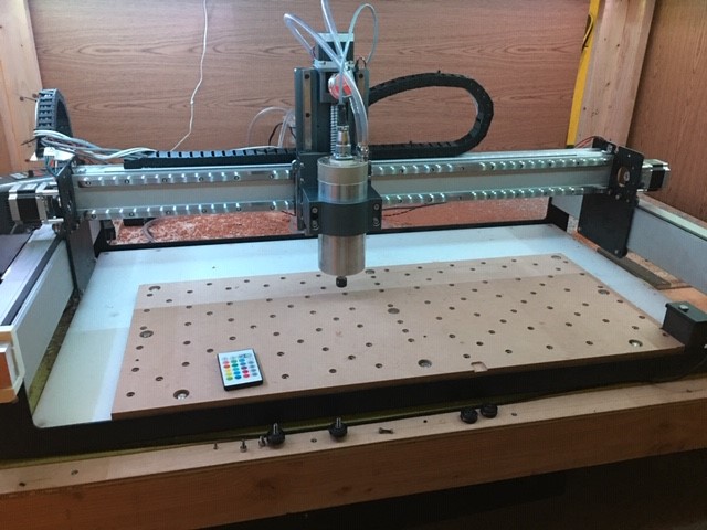
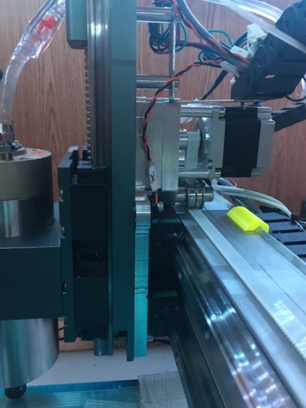
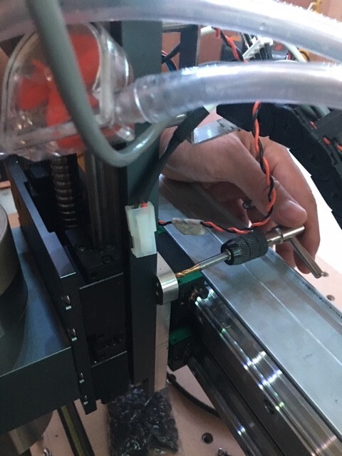
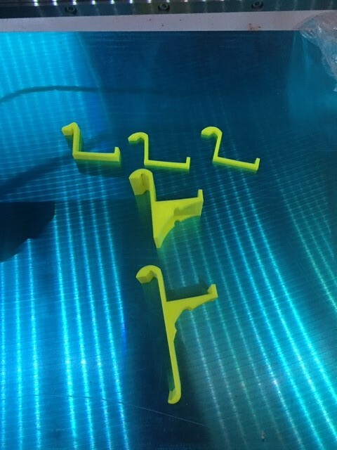
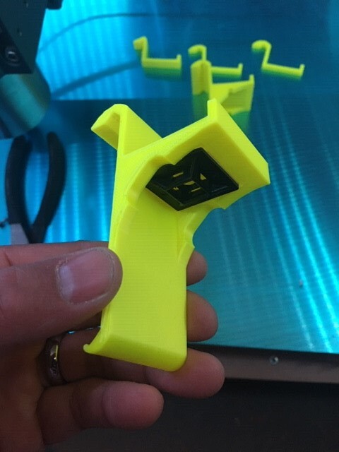
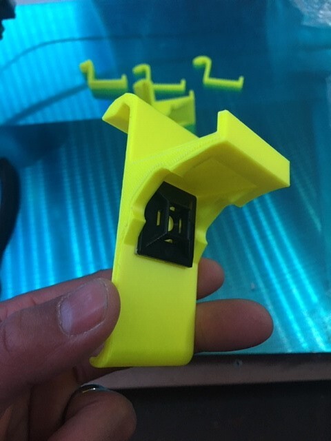
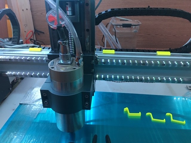
Since I rotated the X-extrusion, the v-wheel rail on the backside interfered with the drag chain by forcing the chain to be a little closer to the X/Z assembly than I would have liked or wouldn’t allow the chain to sit flat. I ended up fabricating a 3D printed drag chain support that hung on the v-rail. It took a couple of tests to iron out the geometry, but I eventually gravitated towards a snap on design. I finally learned how to share Fusion 360 files like normal people.


V-Rail Drag Chain Mounted on X-axis Extrusion
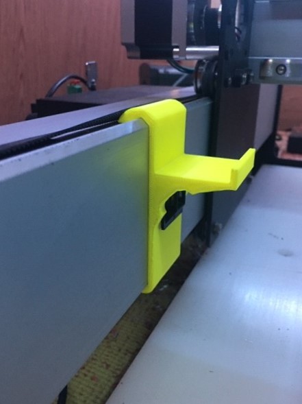
I still have to make a spacer to extend the OEM drag chain mount that’s installed on the back of the HDZ so the drag chain is collinear, but overall this gets me to the point where the moving assembly won’t interfere with the drag chain.

Special thanks to @DanStory for leaving a cookie trail to lead people like me to the promised land; @BartK for giving the community a peek into your process; @Vince.Fab for showing us what’s possible with our machines (and linear guide rails); and people like @fiero1, @diegocolonnello, and @ydrefalk for motivating me to give living on rails a go. @Julien

19 Likes
  1. this is awesome. I immediately edited the selection of forum threads to add this. THANK YOU.
  2. there is no doubt now, you guys conspired to come up with several great linear rail mods posts in just a few days, to test my will.
6 Likes

I was trying to come up with something to really egg you on, but I figured you would know exactly why you’ve been tagged haha. I’m looking forward to @LiamN’s build now that he showed us the goods.

5 Likes

Well…

I think you’ve already done a really nice job of showing us how to mount the rails for the X axis which is what I’ve bought those for.

I’m doing a bunch of measurements of mine before and after the rail installation to see if I can put numbers on it.

Right now I’m reading lots of posts about how to cut Aluminium with the Shapeoko and figuring out if I need ZrN coated cutters, cutting oil, air jet etc. to cut the parts for the upgrade.

2 Likes

Yeah, it’s meant to be a M3 tapped hole on the bumper, one thing that is lacking is a drawing of which holes are tapped and of what size. Sorry about that, documentation is hard :laughing:

Awesome work btw and thanks for the additional write up! Love the idea of the drag chain support clips too.

5 Likes

Deep down in my heart I must have known this, but too much time had elapsed from spot drilling those holes and milling the plate that I was able to convince myself that I could just clear the holes; and that the M3 spiral tap I specifically bought for that hole was for something else haha.

You’re not kidding; it’s easy to forget to capture all of the details.

@LiamN I just wish I had remembered to grab some photos when I had all of the gage blocks and clamps secured on there. I feel like the way the pictures (or lack there of) look, it makes it appear that you can just drill some holes in a straight line and the fit of the mounting holes will align the rails. In actuality I had them looking like the leg braces that the character Vincent had to wear after his surgery in Gattaca image

I’m still kicking myself for not taking the pictures, but I use this technique where I leave my phone somewhere that way, my wife and children know that I’m not just on my phone and also maybe they think I’m doing something relatively quick in the basement/workshop. @neilferreri also has three young children too, he’s got to know what I’m talking about.

Since I still have an MDF wasteboard currently, I just stood by with an air compressor and nozzle to blast the chips away. The ZrN coated end mills are nice but breaking a few isn’t; I am very impressed with the performance of those cheap non-coated single flutes I hyperlinked.

3 Likes

I do everything late, when everyone’s asleep. My bosses (wife and the kids) have me overbooked the rest of the day. I went outside in a downpour yesterday to “check the gutter” just to catch my breath. Ended up sharing the umbrella with two kids I was carrying and almost losing an eye because I let a 4yr old hold the umbrella. I know what you’re talking about.

8 Likes

Dan,

From your original rails thread you mentioned trying out some different grades of tooling plate to see what was flat enough (to meet the parallelism requirements of the rail blocks?), what did you find there? Did you have any particular spec for flatness?

I’m figuring out whether to have the main ZX adapter plate made on 3D hubs or try to cut it myself and if I go 3D hubs I’m going to have to supply some sort of spec for the flatness and parallelism of the faces. If I make it myself I need to choose a grade of tooling plate to buy.

Thx

3 Likes

Hey Liam,

I’m not sure what resources you have close by, but I bought 6061-T651 Type 200 Tooling Plate local to me (added more detail in my original post). I bought the plate to size (.375") measuring with calipers in multiple areas, the thickness was on the money, it didn’t reveal any rocking or gaps when laying it on my table saw’s cast iron top, and if I recall correctly I slid a mounted dial test indicator around the plate to look for any glaring deviations - nothing jumped out at me. I also bought the ATP 5 Cast Aluminum Tooling Plate to thickness, and that seemed good enough for me too.

Since you’re also using an MDF wasteboard, it may or may not be of interest to you that I used @RichCournoyer’s method of dial test indicator and 1/4" shank holder mounted in the spindle indicating on a plate of glass to tram left-to-right and front-to-back to <.005". Using this method, the indicating radius is probably around three inches or so. Dialing in the left-to-right was much easier than the front-to-back.

4 Likes

Thanks,

I look forward to the day when tramming is the next problem to solve in this adventure :wink:

I printed myself up a spindle bracket for the dial gauge so yep, I’ll be tramming on the bed that way. Did you find tramming left right with the eccentrics at the bottom to work well?

BTW, there’s an interesting limit to the flatness of float glass in manufacturing, the local curvature of earth’s gravity.

2 Likes

To clarify, I meant that’s what I dialed the tram to prior to machining the plates for the project. I still have to tram since the rails have been installed. I’ll mess around with the eccentric nuts (where the v-wheels were) if I have to though - that’s a good idea.

That’s the tolerance you should specify to 3D Hubs + or - the local curvature of Earth’s gravity.

4 Likes

And I just noticed in the CAD files that the motor spacer and mount plate aren’t 10mm, they’re 1/2 inch…

Grrr, Queen Victoria’s Imperial units nearly struck again!

1 Like

Yeah, one of my regrets is the design has a mix of metric and imperial units. Sorry about that :frowning: I prefer metric, easy on the math but my mind can only picture imperial. The motor spacer and mount plates aren’t critical as long as they’re thick enough to clear the vee groove but not too far that misaligns the belt too much.

As for tolerance, being no machinist and an amateur at best I didn’t define them, nor sure where to start on how to procure them. Being through-hole mounting of the Shapeoko and my designed parts, they allow for some slop in the system. The biggest factor is the flatness of the plates that mount to the carriage blocks and I wasn’t able to find an specification from HIWIN on the surface mounting outside of the rail height differentiation allowance which is about 0.005" for HG15 series of Z0 light preload. I originally used 1/2" 6061-T6, which has varying gauge tolerance and flatness and surfaced them with my benchtop mini mill to >0.003" flatness across the work pieces. I started to use 3/8" ATP-5 tooling/fixture plate (to cut down on work time and setups, also MIC-6 is an option) which has a gauge tolerance of +/-0.005" (that doesn’t matter as much) and flatness guarantee of <=0.015". Which, well isn’t great for our use case, but due to the short spans of the plates in use (5.5"x9" is my largest stock I start with) hasn’t be worse than 0.005".

The Y-axis is a little bit more complicated because of the dado, which you would want a snug fit (not necessarily press fit). I used gage blocks to get the dado to fit .375" gage block stack and surfaced down the mating plate to fit snug. However if using 3/8" fixture plate, you would just want to use that as your measuring tool. I used stock to leave in Fusion 360 to slowly creep the width of the dado until I got a good fit.

I also see it, It’s still on the base of a Shapeoko platform, it’s still a desktop CNC. I’m not going to try to aim for tenths precision. I mean, I used knock-off HIWIN rails and carriage blocks. They aren’t going to win awards or match HIWIN tolerances and spec’s in my eyes. But they make my CNC much more approachable and desirable results for my hobby use.

5 Likes

The other thing I did for the dado was I would sweep the floor of it to make sure it was level before surfacing the plate down. With fixture plate as the stock, I would just sweep the top, this is so the floor is parallel with the mounting surface.

1 Like

Great, thanks for that, clarifies a lot and answers a couple of questions I hadn’t realised to ask yet :wink:

The CAD files are super helpful to figure out what’s going on and to have a solid place to start, unfortunately Fusion 360 cannot change the display units in an existing file apparently so, despite many of the measurements being input in mm it will only show them in inches. I’m cloning them into mm to work from.

I’m just trying the X at the moment to see if I’m OK with the remaining slack after fixing the worst offender. We’ll see how long I can go before the Y beams get railed. Once I’ve done the X I may feel more comfortable cutting the more complex parts for the Y.

And I’m with you on the achievable precision thing, if I want microns I need a mill, not a CNC router.

3 Likes

I imagine using angled supports for the Y-carriage assemblies like @Ddemnard would palliate the importance of a perfectly snug dado. Thoughts?

1 Like

Disclaimer: I’m no expert, this is just from my limited knowledge and experience. :sweat_smile:

The dado is to prevent radial forces/load on the screws that mount the two plates together, this reduces the chance of screws from shearing, compared to a butt joint. I don’t think the cross brace will help prevent that nearly as much but would of course help forces in other directions with the additional rigidity.

And of course they’re plenty of joints on the Shapeoko that are merely a butt joint :stuck_out_tongue:

:+1: that’s been the advice I’ve given for those that have reached out directly. Start with the X-Axis, you’ll get large gains with little effort compared to the Y-Axis. You’ll then have a more solid machine to tackle the Y if so desired.

3 Likes

Looking at the suppliers over here in the UK it seems that the tooling plate I can buy retail in small sizes is 5083 which I understand isn’t the easiest stuff to machine.

Meanwhile I’m learning how to put the DG&T parallelism and flatness tolerances onto a drawing to see what the final price from 3Dhubs would be in a nice 7075-T6 anodised for the main XZ plate, leaving me to machine the easier parts as my learning path.

Any reason not to use a suitable extrusion for the Y plates rather than jointing plate?

As I read more it appears to me that quite a lot of the damping in the Shapeoko is actually friction damping at all those bolted joints helping to leech away vibration and resonance energy.

2 Likes

From my understanding 5083 is the same as ATP-5 (or at least “Modified 5083 Aluminum Alloy”). Just a matter if its pre-machined with in the same tolerances.

I’ve been told the tool plate can be more gummy compared to 6061-T6, I hadn’t had troubles with it when using single flutes but only has been with my modified Shapeoko, not before the mods.

Cast Aluminum Tooling Plate or Jig Plate
Is known by various trade names:
Mic 6® (a registered trademark of Aloca Inc)
Alpase K100-S® (a registered trademark of TST, Inc)
Alca 5™ (a trademark of PCP Canada)
Vista Metals ATP 5™ (a trademark of Vista Metals Corp.)
Alimex 5083

At least from composition, they seem to be the same:
Aluminium
Chromium: 0.05-0.25% max
Copper: 0.1% max
Iron: 0.4% max
Magnesium: 4.0 to 4.9%
Manganese: 0.4 to 1.0%
Silicon: 0.4% max
Titanium: 0.15% max
Zinc: 0.25% max

2 Likes