Not sure if it makes a difference but I do see one more vector is selected in v7 vs v8 ( 121 vs 120 )
1 Like
So I am upgrading to the 80mm spindle this week. I just bought the pro license tonight.
Figured instead of me having training
Bowl V8.c2d (56 KB)
on V7 why not the newer V8 beta since in future this is what I will be using.
So I have a slab of Curly Walnut that is 2.2" thick why not try and make a huge drop tray.
I have IDC the hog and a 3/4 ball/bull nose bit.
I also have a round over bit but I can’t find the tool in database.
Can someone look at the file and see if I am doing this right on design?
Can’t really advise on tooling which I don’t have.
For roundover tooling, see:
Thanks. Have checked and no idea what is causing that. What I have just noted is that in CC7 inlay plug mode has a tick in the box. But when I replicate that in CC8 it causes the output I show above. CC8 is making a pocket rather than the inlay part protruding up like it should. Is CC8 handling inlays differently from 7?
Thanks for the help.
Josh
Stand down everyone ![]() . User error. went back and watched the video below. I forgot to select the song TP AND its boundary! I was just doing the song.
. User error. went back and watched the video below. I forgot to select the song TP AND its boundary! I was just doing the song. ![]()
Josh
On the pocket, your depth of cut is 0.375". Seems a bit aggressive to me.
Then you start at 0.600" and cut down to 1.000". Your first cut will be at 0.975" fully engaged.
1 Like
Sitting here in the Dark had a idea Whats the chances of getting a dark mode switch programed into the software I think that would be cool. Less eye strain. ![]()
2 Likes
If you put Windows into High Contrast mode it will somewhat darken some aspects of the UI.
I use Mac I tried Night Shift but still really bright. Ill mess with it see if I can make something work
When will Carbide Create Pro Ver 8 go live?
Thanks
Probably next week if nothing gets in the way. It’s ready; we just haven’t moved it over yet.
4 Likes
I’m making a cameo from a height map, the bust is set in a recess:
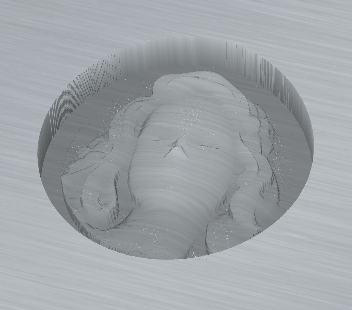
In the Model pane I have a flat ModelShape equal to thickness of the substrate, 8.0 mm. The heightmap element is subtracted from that. The perimeter of the recess is a Contour cut equal to the depth of the heightmap element. All is fine so far.
But I want to lower the carving a bit so that after it is inlaid I can safely sand the outside perimeter without doing a nose job. It seems plausible to do this is by lowering the Base Height of the heightmap. Here I’ve exaggerated the amount to show the issue:
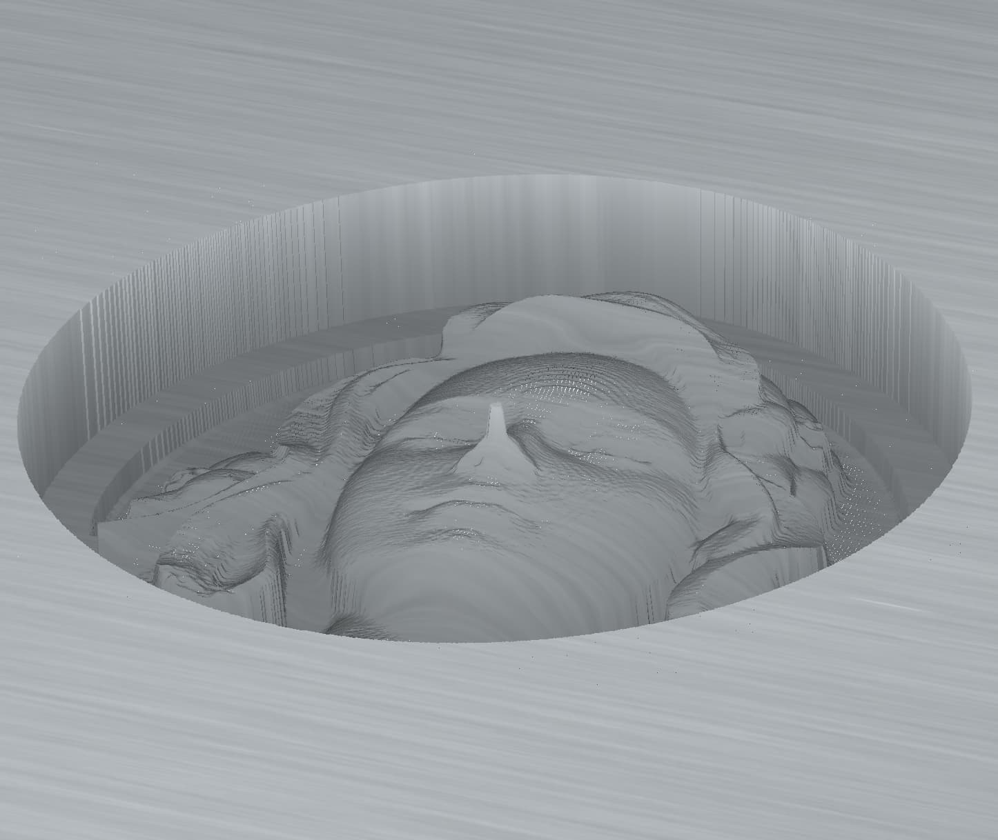
I’m still getting my “sea legs” with 3D, it’s a new thrill every day. File enclosed, any ideas? BTW, this doesn’t seem to happen when I use the STL on which this was based.
Sophie_3_htMap.c2d (872 KB)
I suspect this is a difficulty in how the 3D model is stored.
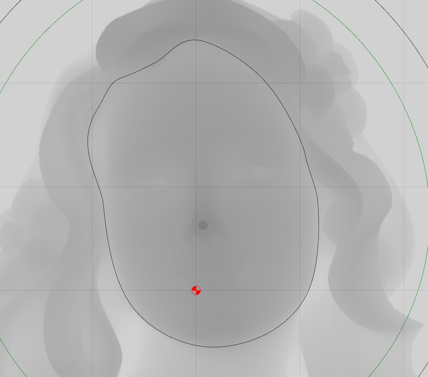
That dark nose circle in the heightmap only shows in CC when I make the Base Height non-zero. The heightmap was created in CC by exporting it as a png. It was modified in Affinity Photo, that aberration didn’t appear there either. It’s unclear to me how this, if somehow a function of the stl, could have been retained in hidden form in a png.
After further testing: I opened the png in AffinityPhoto and exported as a jpg, the problem went away. I re-opened the jpg in AP and exported as a png. The issue returned.
I then tried another png heightmap from another figure:
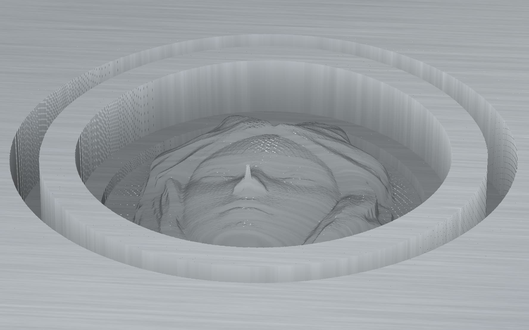
I repositioned the model, also cut out the nose so another spot was the darkest in the heightmap. In both cases the spike was emanating from the darkest region in the heightmap.
Am I possibly the first to try a carve, with a png, where the highest point is below the top of the substrate? Or is there something unorthodox in my approach?
EDIT: I painted a new file in AP, from scratch, saved as a png. Same result.

It appears, at least using my workflow (I know no other), that CC automatically forces the darkest part of a png to the top surface by creating an artifact at that position. That area does not need to be 100% black for this to happen.
1 Like
In the v8 beta you can reposition an STL model by dragging on the dashed rectangular selection box when the model is selected in the Model pane. But as soon as you edit the model it snaps back to the original position. Anyway to freeze it there?
1 Like
Sounds like a bug.
I’ll make note of it and we’ll see what can be done.
1 Like
Can you post the STL alone?
1 Like
I can if you’d like but this happened not just with the png’s created for two different STL’s, it also happened when I created a png without any STL source.
Oh, maybe you’re referring to my subsequent post involving the re-positioned STL snapping back when edited? This also happens with two different STL’s.
It appears there is a limit of the file size of 4 Mb, the smaller file is 4.5 Mb. I can arbitrarily delete some polys to reduce file size if that’s of use.
I think clicking this will fix the file you posted (basically, it leaves the sections that seem to be in the background of an imported STL file):

1 Like
Hello,
I am having an issue with tabs not being created during a design or when I am cutting the project out with a contour cut. I tried to attach the file for the project but it is too big. Not sure if I am missing something or if it is an issue with V8.
Thank you,
Mike