I would love to be able to take a vector and overlay it onto a curved surface and have it be able to follow that curve. For example if I had a dished surface and want to carve an image or word on the bottom, it would be great to be able to use an advanced Vcarve to follow the contour of the 3D surface. Similar to what’s done in this project.
Before seeing this forum this morning, I emailed the support team asking for help understanding a few features within the Modeling Tab pertaining to importing and working with STL files (I will post the email with pics below). Although I am a fairly accomplished woodworker, I am considered to be an extreme novice in CNC. I have always realized the value of using them for my projects, but I never had the money or the time to purchase one before. Finally, I purchased my first machine, a Shapeoko XDXL, earlier this year and have enjoyed learning how to use it. By watching the tutorials and by trial and error, I am steadily gaining confidence in designing and making 2D objects. I was asked to make a 3D object, and this is where I have run into trouble; read the email posted below;
Good morning. I am writing to ask if someone can direct me to the right place. For the past couple of weeks, I have been trying to make what should have been a simple design, attached below.
Vector Badge 2.c2d (744 KB)
Before attempting to recreate the coin front into a wood surface, I made sure to watch all the Carbide Create training videos first. However, I found that the guy who does the CC training videos moves a little too fast for someone who has never done this before. The videos assume that you already have a basic understanding of the settings and what they do, so he does not go into detail on what exactly each setting does and how it affects the piece. So, I decided to try watching unsponsored videos on YouTube, but there isn’t much content out there to pull from.
Going with what I thought would be correct, I purchased an STL file of the badge (attached) and began building what looked to be a fairly straightforward project. My plans were to have the badge raised to about 3mm or 1/8in with an outside ring at the same height. I imported the STL file of the badge and created a 1mm outside offset. Then, I set the height to 3mm with a Merge Type of ADD and created a 3mm pocket tool path that ran from the outside edge of the badge to the inside edge of the outside ring. After creating the lettering that was to run in the circular ring around the badge, I created another 3mm pocket toolpath that ran from the outside edge of the ring to the edge of the stock.
In theory, the badge, if rounded, should have had the edge of it beginning 3mm below the surface of the stock and the middle even with the surface. Once the interior and exterior pockets were cut, then both the badge and the ring would be raised, leaving the overall thickness of the rest of the stock 3mm less tan when I began. Since I am using 3/4 inch MDF for test pieces, that means it should have come out to about 15.3mm or .6 inches, which it did. Everything on the design worked fine except for the badge. No matter what I do, I cannot seem to get the badge to appear raised (embossed) inside of the ring. I know it is a simple setting issue because the badge is either cut way too deep or the bit barely touches it, so there is nothing but a few little lines on the badge face.
Either way, I am having issues trying to create this model, and I was hoping someone could point me to 3D tutorials that are made for the extreme novice. As I said before, I attached the STL file, but being a novice, I am not sure how to make it do what I want. I assumed that it would come with the toolpaths necessary for making it raised, but I found it doesn’t work that way. I really need a resource that explains in detail the import and shape parameters and how they relate to each other, as well as the image itself.
Please, if someone can point me towards a resource that slowly explains in detail the various settings and their relevance to the overall image, let me know. Thank you.
Please add to the new version the ability to move the 2.5D model elements after they are defined.
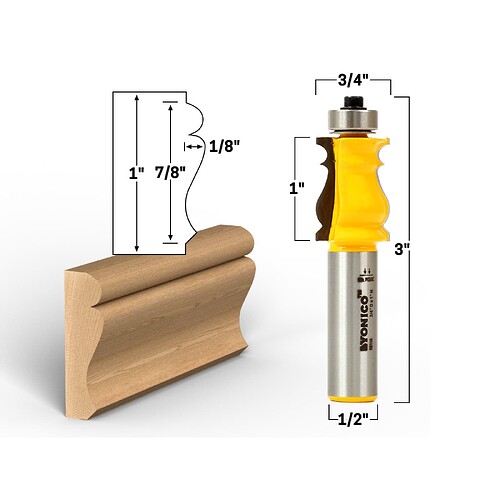
This is just a generic thought that would address many issues with creating parts and reliefs in CCP. In this example, could you make us a picture frame using this profile? I can’t seem to change radii to a contour like the middle section of this trim; a tight radius built up on one side that blends to a much wider-radiused valley. I’ve only achieved this by creating an extruded part on freecad, then exporting an stl image, with varying degrees of success.
Pulled from the alternate thread Will started on the subject.
I do a lot of basic topography projects. The software can make the project fine as it is, but a couple improvements could go a long way for my use.
They are custom requests, and I need to show renders to confirm with clients. The lighting in simulation is tough on topographic models, especially from a top down perspective, but giving the customer high-res stl’s can raise expectations beyond the resolution that the wood/chosen bit can provide.
I use primarily black walnut as stock material, but there’s no render material for that in CC, so I stick to aluminum (again, for the lighting).
I constantly have to remove the 3d model and replace it despite taking up the same boundary box. Updating/replacing a model would remove a lot of fiction for set projects only needing a new stl file. Right now I need disable/delete the old one (which sometimes deletes other models, but I don’t have a way to replicate that), import a new one into the same boundary line, put in the same height settings/scale info and then save/run the project.
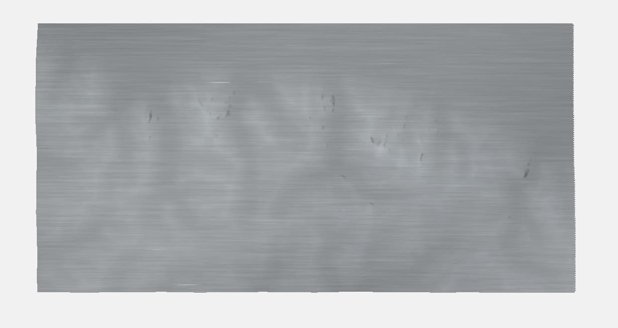
Top Down:
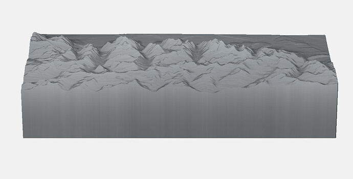
Front Side:
Really poor capture of CC Pro v774 deleting 2 models at once: https://imgur.com/a/644640H
I’ll admit, I haven’t tried to make these yet, and likely could with the existing tools, but these are some of the 3D projects that I’ve been wanting to try.
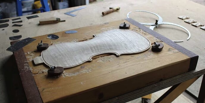
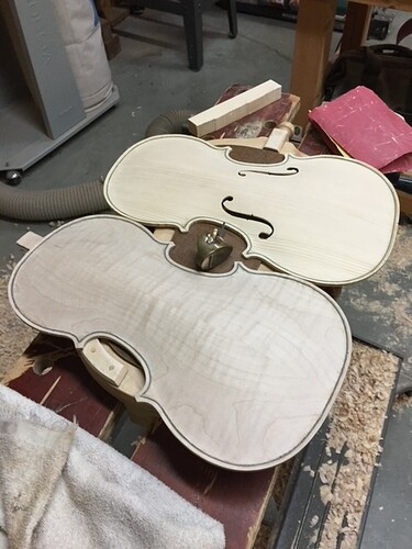
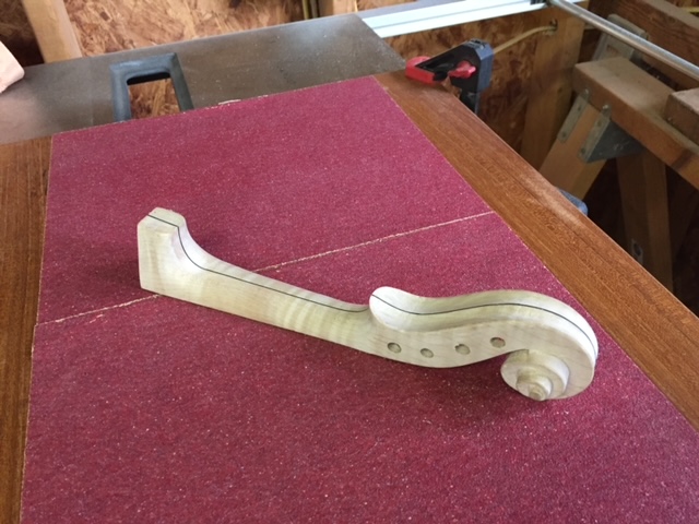
Custom, 2-sided profiles that I’d then turn into bowls, instrument tops, or just carvings from 3D files. (Violin image is not mine)
Continuing the discussion from CC Pro - What do you want to make in 3D?:
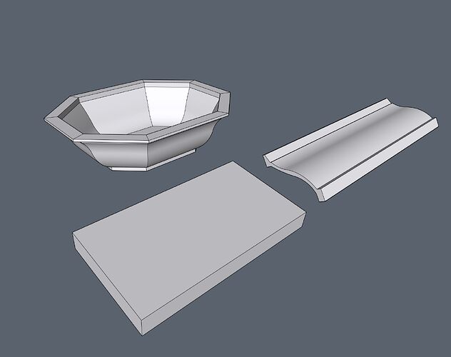
I would like to be able to make more complex and stacked 3d designs like in other CAD programs. I have attached the image from the web as an emample. If the software could stack shapes and then let them be moved in a 3d grid it would open up the capabilities significantly. Also having the option to split the design into multiple pieces would be great to allow for machining of complex profiles.
Cheers, Julian
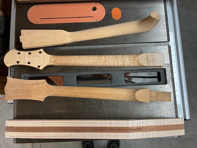
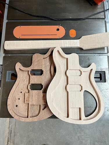
I build guitars (mostly electric these days), and I use the 2.5D capabilities of CC Pro to design and cut the (many) pockets and positions for hardware - and I am very satisfied with what I am able to do (so far). What I am very, very interested in having is the ability to accurately design and cut a full-scale guitar neck. There are many factors that require close-tolerance precision in part placement as well as shape(s). “Kinda round” and “sorta the close angle” are not in the luthier’s handbook, so definable thicknesses and precision placements are a must. I know it exceeds today’s capabilities, and might not come all-at-once, but with @robgrz making a very kind request, I thought I’d shoot for the moon. Thanks!
I keep running into the same problem with the Model facility. There seems to be no way to use tabs. At least I haven’t found it.
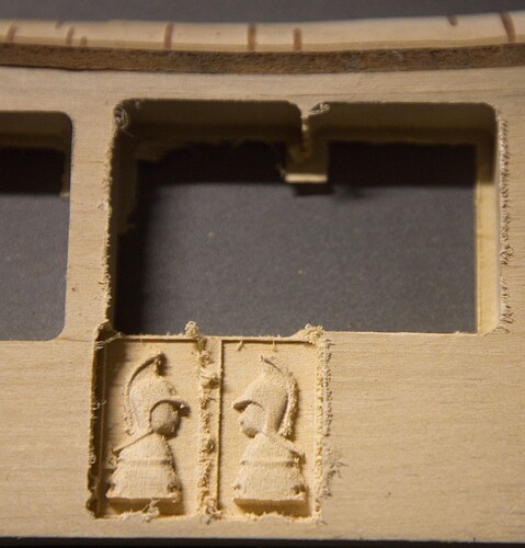
I’ve tried carving several different 3D objects in two separate sides - each 50% of the complete volume. The carving below illustrates. (My apologies to all who have posted fine examples of craftsmanship, but this shabby little object gets to my point.) These little objects are intended to be halves of a tiny chess pawn under 3/4" tall. I could use the tape and CA glue hold down, but I’m not confident the tape would hold enough to carve all the way to the bottom of the stock. So I added a flat base within the model. However, now I need to remove (resaw?, router?, sander?) the base without destroying the pawn parts. Tabs seem like the logical CNC solution for any such work in which the perimeter of the object needs to remove stock to the bottom.
I am fairly new to CCP but have found the 2D option to be pretty straightforward and simple to use, but the 3D option is a different animal altogether. As I started a project that included a 3D police badge, I found some impossible limitations to overcome. It may be due to my lack of knowledge of the operation, and someone with more experience may be able to complete it without any trouble, but I had to abandon the 3D portion of the project and opted for the 2D version of the badge.
I was trying to make a simple plaque with a 3D badge in the middle, so I purchased an STL file online. I loaded it into CCP, and it cut the image fairly well. The issue I have is that I cannot find a way to add text to the badge. I downloaded Blender and Inkscape, hoping that I could add it through one of those programs, but it was not to be. Again, it could be that I just don’t have enough time behind the mouse when it comes to operating the CAD programs I mentioned, but it would be nice if there were better options in CCP for 3D file manipulation.
Part of the problem is that nothing is ever created with the layman in mind, such as when importing and then using an image by way of the 3D Import feature. For example, once you have a file that is capable of being read as a 3D file and import it into CCP, it becomes extremely confusing for someone who has never used the option before. It would be helpful to the 3D newby, such as myself, that when hovering over any one of the Import Parameters, the program would let you know what the settings are and what they mean.
I might not have looked in the right place, and I might have missed something, but after watching all the videos, I was no better off than when I started. Although the guy doing the videos is very knowledgeable and obviously knows Carbide Create inside and out, he moves so fast in his explanations of each function that if you are not already familiar with how everything works, you are easily lost. As a result, I turned to YouTube and various other random websites to try to figure out what I was looking at and how to use it. The lack of specific information on each subject is very frustrating and could cause someone to turn to a program other than Carbide Create, although I have no idea where one would turn.
I think that Carbide Create would do well to create a series of videos that specifically target those who are new to CNC and have never used the 3D carving option before. The videos need to move slowly enough for someone new to the CNC world to follow along. Either that or build the software to display a pop-up when hovering the mouse pointer over a setting that explains what the setting is and how it affects your carving. As the CC training videos gave a good general overview of the functionalities of my Shapeoko XXL machine, it has taken me forever to find out the meaning of Height, XY Scale, Remove Z Height, Merge Type, and Base Height, and I am still foggy on a few of them. I might have figured them out by running the carving a half dozen times on scraps, but I am not confident enough to put it into a good piece of wood.
With that said, does anyone know of a website or someone who is skilled at working with STL files who can help me with adding text to to the image? The learning curve for any of the CAD programs is insane. I only need to add three words in different places on the badge. Two of them are curved, and one is straight. I would attach the file to this post, but it is too big, even when zipped. If anyone has suggestions where I can get some help, please let me know. Thank you.
If you can upload the file to google drive, one drive, or any other cloud file storage that let’s you share, then you can just post the link here.
For 3D you can build components individually and add, subtract, etc… them to make a single shape.
Or you can import an STL that has been modeled. Then if you want you can add shapes to that.
So if you have a STL badge
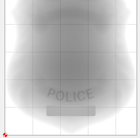
And let’s say you want to add the badge number under “POLICE”
Create a text object for the number and center it in the spot you want it.
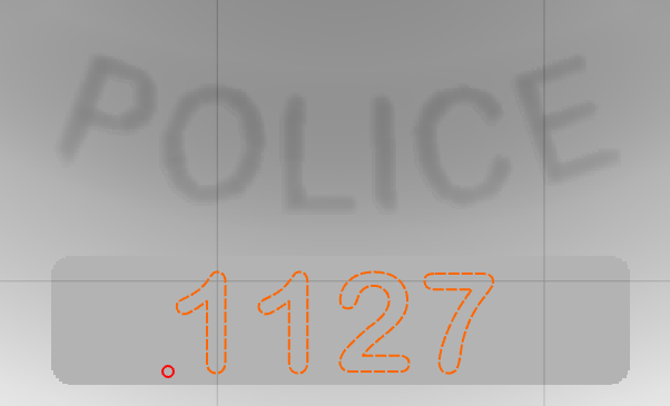
Now use that text to create another 3D element and add or subtract it from the model.
The project that turned me on to CNC machining—and 3d printing and making in general—but that I have not yet accomplished: custom, shop-made watch dial!
I was going upload the 3D file that I had been working on, but the file is too big to upload. Says I can only upload a file the is 4mb or smaller.
It has been awhile since I used 3d, basically I tried it and gave up.
-Crashed quite a bit in 3D for me.
-Ability to make changes without deleting. ( that was a big pain for me )
-Importing the original Z height seem cumbersome if I remember. you had to give it a height in units verses a percentage or original IE if STL was made 100% to fit by an external program. I believe you have to go back into the other external program and write down the original height then maybe convert it and then enter it into CC pro instead of just taking it in as 100%
I believe the drag tools did not snap to grid
When using the drag tool there is no real time indications of the scale it is being stretched to, or the rotation until you dropped it. It would be nice to see the scale and rotation real time as you drag them.
The ability to use the tools “3D cutting Parameters” in 3D tool paths.
The ability for the “cutting parameters” to use formulas and percentages. IE stepover =15% or =0.15 x (tool diameter)
The other item for me was the Engrave. I believe this has caught several people with the one pass depth. Setting the “Depth per pass” in the tool then setting the “Cut Depth” changes the “Depth per pass” in the tool without informing you. And it also gets confused with “Max Depth”. Max depth is a multi pass while cut depth is single pass. I finally figured it out but wow what a learning curve.
I would very much like to see engraving support multiple pass engraving so it supports not only drag engraving but PCB engravers. I engrave lettering in aluminum face panels. which require 3-4 passes.
I believe I ended up setting 4 tool paths. each one a but deeper.
Hope some of this helps
I’ve only dabbled in the stl import stuff for a little bit. It’s not very intuitive and I don’t like how you have to stretch or define the z axis. Can we not import an stl as it is designed? Like if I need to make a mold for a propeller, I wouldn’t exactly be able to figure out the appropriate z height with how 3D is currently setup. It’s very possible I’m missing something so please correct me if I’m wrong. Just seems like the 3D aspect of CC Pro is used for random art that doesn’t matter if it’s dimensionally correct.
Kind of surprised how different 3d printing slicer software is compared to cnc gcode software. I’ve used a few different cnc gcode software with 3 support and they kind of all take the same approach and it just doesn’t seem intuitive to me. Is there a reason it has to be like this? Why is the 3d printing slicer so much different other than it’s additive vs subtractive process.?
I believe that if that is what you want, then the answer is you would use a traditional 3D CAM tool such as MeshCAM:
I think you hit the nail on the head with, “…doesn’t matter if it’s dimensionally correct.”
Most of these machines have limited Z travel, and many hobby/decorative jobs just need the height to fit in the stock, rather than being dimensionally proportional to the original. i.e. the current feature works for ‘most’ projects.
There’s another thread where several have asked (myself included) for the Z scale to come in proportional to the XY scale, then allow us to change it if we want to. It already defaults to, I think 0.118" or 3mm, which at least I’ve never used, so I always change it.
If it comes in proportional, we can at least quickly calculate the original size from the scale.

