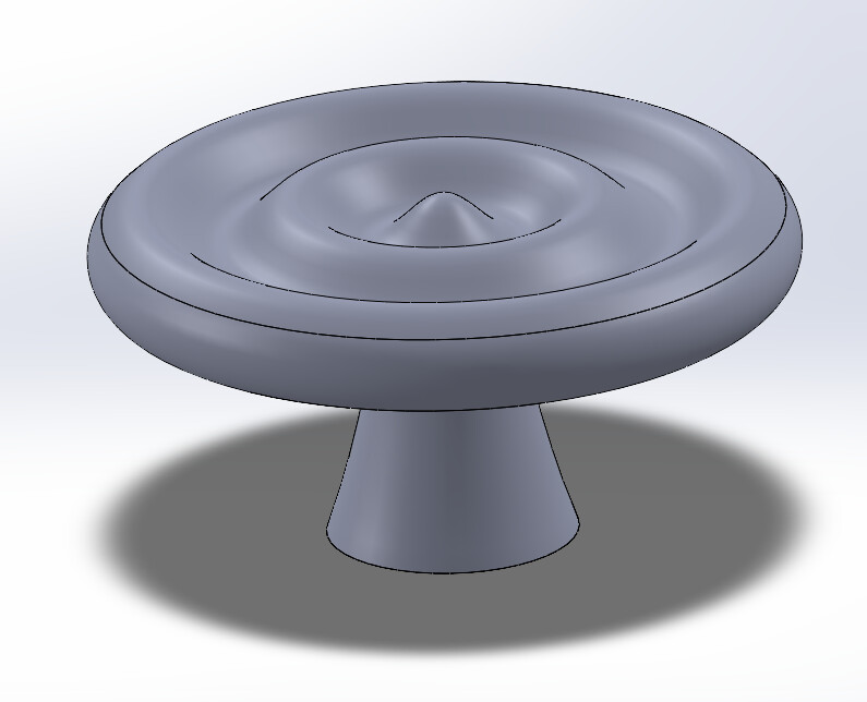
I’m trying to make cabinet pulls with a cool pattern on top. I’m about to make a post about an issue I’ve been having with the tool paths flattening the tops of them though… Anyway, the idea is to carve the ripples on top of the pulls and then cut out a nice round piece that I can then finish on my lathe for the backside. I’m also planning to use some CNC’d fixturing to mate up to those ripple lines to press the produce between the drive side and the tail stock.
1 Like
Aloha,
I bought a Shapeoko 5 Pro to prototype and test the surfboard fins I design and manufacture. I only received the machine, so I have not yet assembled it.
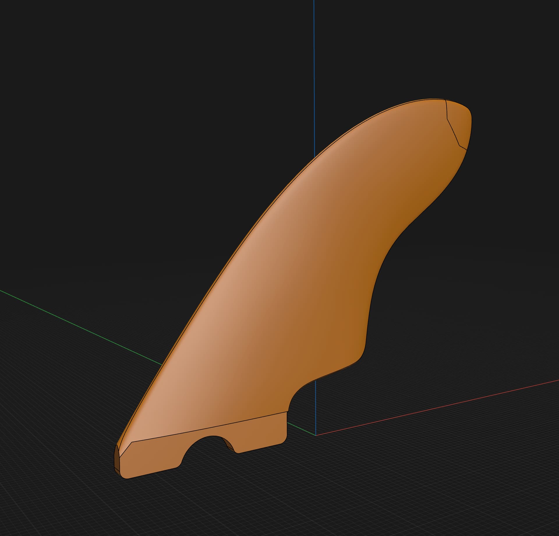
But I need to be able to 3D carve something like the attached image, which does not show all of the detail. However, it has foiling on both sides and is completely asymmetrical. The foils are reasonably complex, so I’m trying to understand how to do this in CCPro. This is just one in. There would typically be a mirrored copy for both matching fins.
We manufacture fins like this on industrial CNC machines based on scanned models of fins I create by hand. I’m trying to eliminate the need to send actual fins to our factory. Instead, I want to be able to scan a fin, then CNC machine it to see if there are any problems with the model, before sending the model to the factory for production.
I’m not sure if the image will come through, as this is the first time I’ve tried to post something.
See:
https://my.carbide3d.com/gswccpro/07/
and also see
and
— note that only binary format STL files may be imported:
if you’re still stuck, upload a sample STL and we will walk you through it.
There are some bits that can be used that will do all of this same cuts you have on this pull, and they would more then likely do it in much less time then your 3D design. I can’t think of the name of them at this moment but they have rounded tips that would cut the valleys you have in your design. They could possibly be cut in one pass.
Also, roundover bits may be able to do this design as well, but they would have a much more pronounced valley point. But anyways, hope these pulls come out good for you.
You can use a cheaper laser scanner to capture the points and turn it into a 3D mesh ( stl or obj format).
I have a chinease 3D maker device which comes with JMStudio for processing.
Both are ok, and a bit cryptic in workflow.
I have used Fusion 360 to import the mesh, and do a minimal repair on the mesh.
You can use the mesh as the model for CAM work in Fusion or export to whatever.
This is probably what you manufacturer is doing.
The real trick is how to fixture the process. I do not have a solution for that.
Yes, I just got a 3D scanner to scan myself instead of relying on the factory. I’m in the process of setting it up and getting it figured out.
4 posts were split to a new topic: Cutting Surfboard fin
Is this a two sided cut ? I see you have some tabs in place.
Nice website
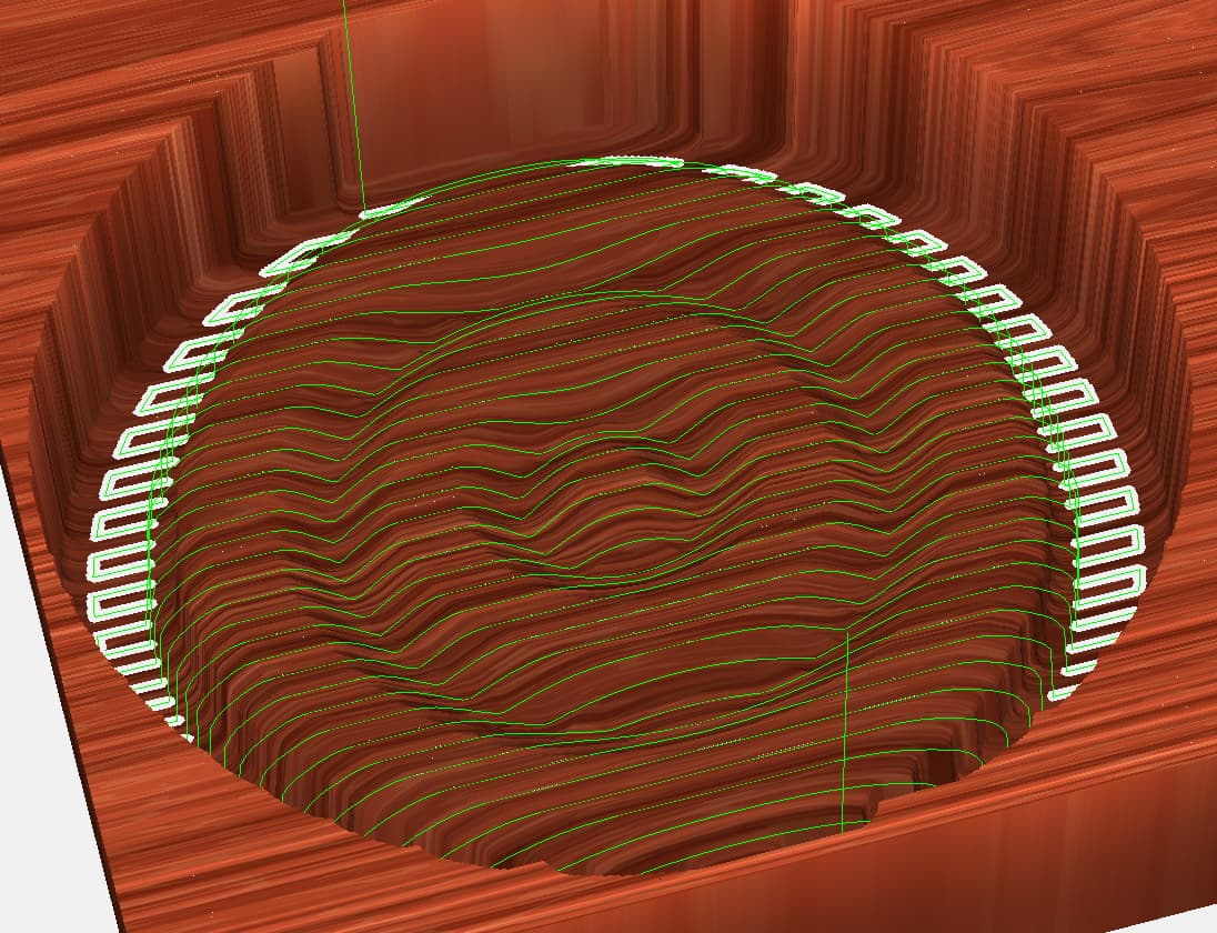
I’m using a 1/8" ball end mill, but I discovered that my “custom” 1/8" ball end mill was not rendering correct toolpaths. If I use one of the included ball end mills in the software, the paths come out like they’re supposed to. I still need to do some experimentation to determine the surface finish of the end product. I’d also like to use circular toolpaths for efficiency, and I’ve already worked out 90% of the geometry by hand. Somewhat unfortunately, I’ve decided I need to write some code to create my own g-code in order to do it efficiently, so wish me luck on that ![]()
Good luck on the programming.
I appreciate Will’s step by step instruction how to do the project, but is there a video or explanation “Why” certain steps are needed? Why would it take 3 circles to create a single dish shape? Is there a more basic tutorial that starts from the beginning?
Art, can you link Will’s instruction where it takes 3 circles? I suspect maybe 2 different radii? Or maybe the offset for the inside/outside (top/bottom)???
1 Like
Presumably one wants a lip which does not rise to a sharp point. Note that this is the same misunderstanding which causes some folks to believe The Bible indicates pi to be equal to 3.
Link to the discussion in question? We’ll gladly review this with you.
1 Like
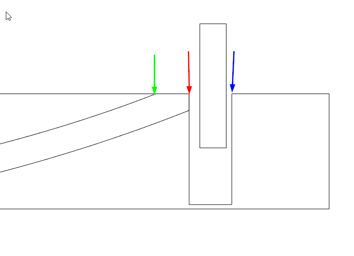
OK, I think I see which example you mean. the Fleur de Lis bowl (Instructions on How To 3D Carve using CC V7 Pro - #12 by WillAdams)
The inner circle (green) is the edge of the concave bowl shape. The next circle (red) is the outer edge you will trim to. and the third circle (blue) is an outside boundary for the trim cut so you can use a pocket toolpath rather than a contour (profile) path.
1 Like
This topic was automatically closed 30 days after the last reply. New replies are no longer allowed.