I made a edit. I tried to upload two videos but wasn’t able to. Gave me an error.
Yes, for videos one needs to upload them to a file/video sharing site of their choosing, and then insert a link in their post. The forum does not support direct upload of videos. If it is a small one you can zip it, since the .zip extension is accepted (but there is a small size limit)
Thanks. Another edit. Inserted hyperlink
I have a YouTube account I’ll be linking to very soon.
Sometime after Tuesday.
will a drip coffee stand work as a kitchenware?
It should!
Because it’s used in the kitchen!
I’m not one to argue too much, do post about your drip coffee stand!
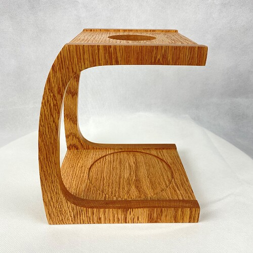
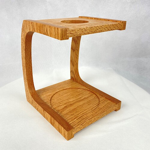
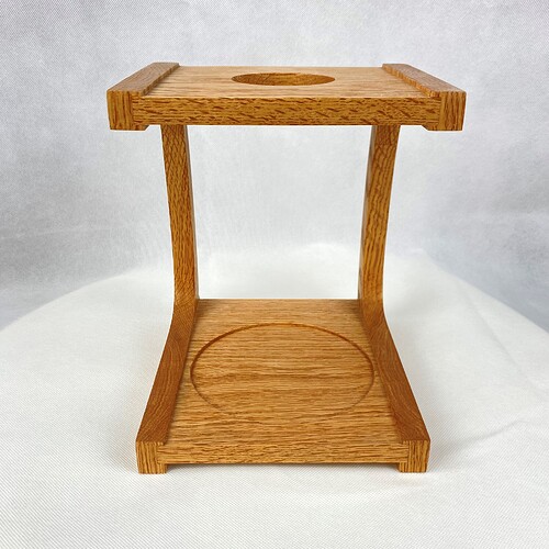
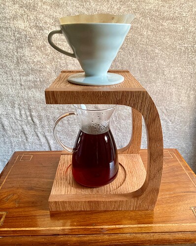
I was ways fascinated by the taste and the methods of brewing pour over coffee, recently i have bought a shapeoko pro and asked my self why not use it to fulfil my coffee addition needs by making a pour over coffee stand :). In this post i would like to share the project photos and my experience with the community summarised in the below points.
Before starting any project i usually develop a list of Design consideration and objectives, below is what i have developed for this project:
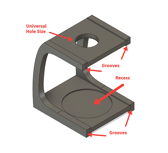
- Eliminate the use of dowels by making grooves to fit the pieces together and for better alignment during glue up
- Drip hole size to be compatible with various coffee drippers
- Make a recess to collect coffee droplets
- Able to fit a small measurement scale, to measure poured water
- Able to fit several types of coffee servers
Machining considerations:
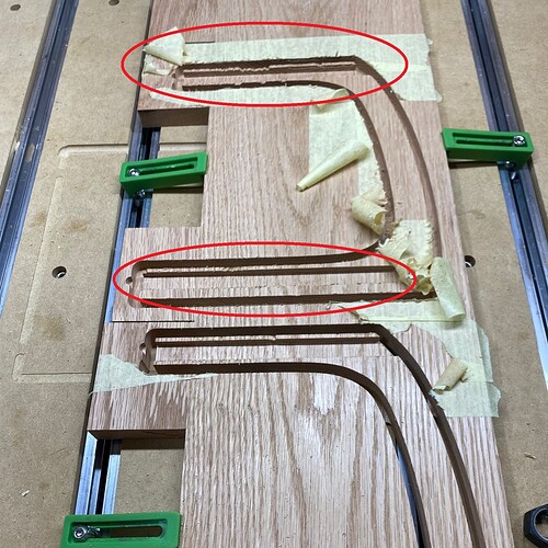
- I had few failed attempts since i was cutting across the grain in some areas with an up cut bit which splintered the edges of the wood, i had to change the upcut with a downcut bit which solved the issue.
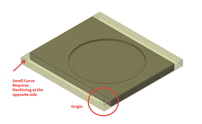
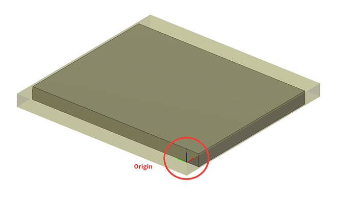
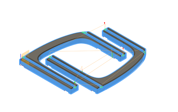
- Since some parts such as the lower plate required two side machining due to a curve at the edge. Therefore. I had to create two G-Codes in fusion 360 one for the upper face and one for the lower face. For this to work you need the origin point to be at the same location while maintaining a Z Axis perpendicular to the face that you will machine see below photos. After that all you need to do is to flip your stock before running the second G-Code.
- Parts were cut in two operations a roughing pass and a finishing pass to maximise the precision of cut parts, i left about 0.5 to 1 mm stock in the roughing pass to be cleared in the finishing pass.
Feeds & Speeds:
-
Majority of the parts were cut with a 1/4 inch flat up cut end mill, used a feed rate of 65 in/min at 18000 RPM. (Bit #201 supplied by Carbide 3D)
-
Curves were cut with 1/4 inch ball end mill, used a feed rate of 65 in/min at 18000 RPM. (Bit #202 supplied by Carbide 3D)
-
For grooves i used a down cutting end mill to minimise chipping with a feed rate of 100 in/min at 18000 RPM. (bit supplied by Amana Tool 46202-K)
Wood Finishing:
- Since i ran my stock (Red Oak) in a planer, sanding was reduced significantly. Therefore, I have used 120, 150 and 220 sanding papers consecutively. Then i have applied two coats of Danish Oil to expose the natural beauty of wood gran and for liquid resistance.
Nice coffee stand ! Thanks for participating. It’s also quite doable in Carbide Create so hopefully this will inspire others to make their own.
Very Nice Coffee Maker, Maker.
I don’t know why my mind does that?
I hope this qualifies as Kitchenware…
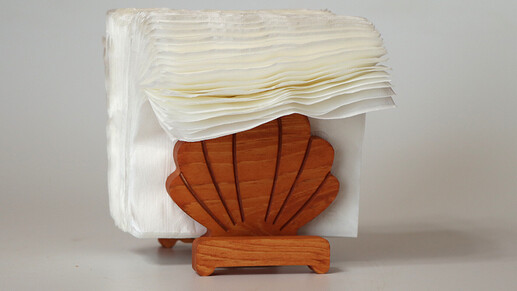
A Napkin holder.
Cut out of 3/4" pine and stained with some random orange stain I had sitting around from another project.

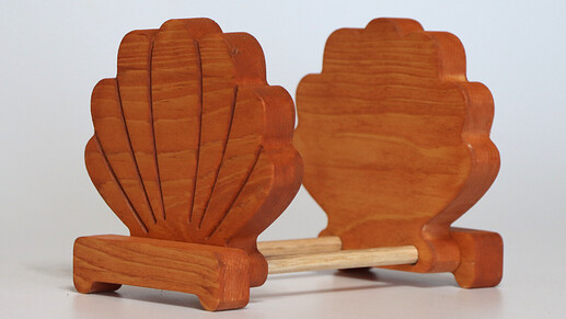
The design is super simple, the legs are both mirrored as are the shell shaped napkin ends.
Finished project stands about five inches tall, just under five inches wide and as long as you’d like. I used six inch dowels to join the parts together yielding about six and a half inches finished length.
You can download the project file on cutrocket here.
Arguably the most critical and important tool in the kitchen (maybe debatable). 
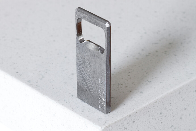
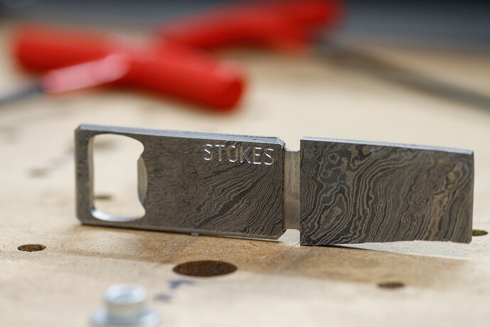
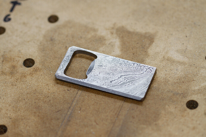
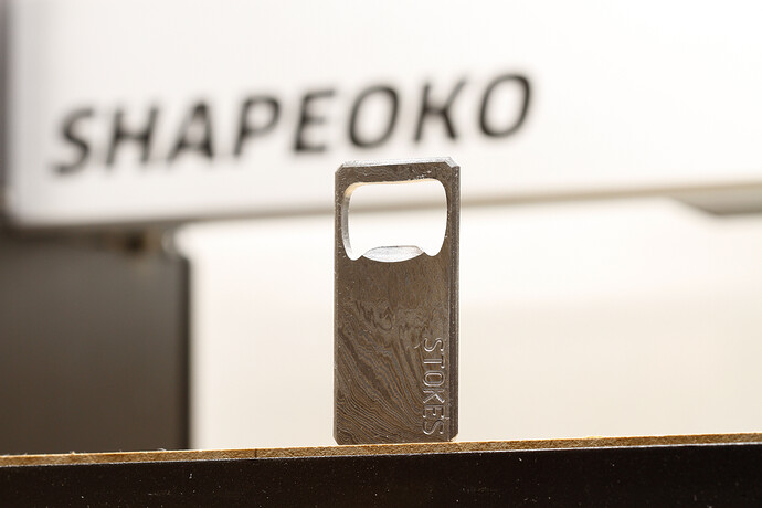
Damascus Steel Bottle Opener
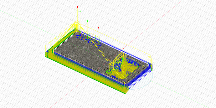
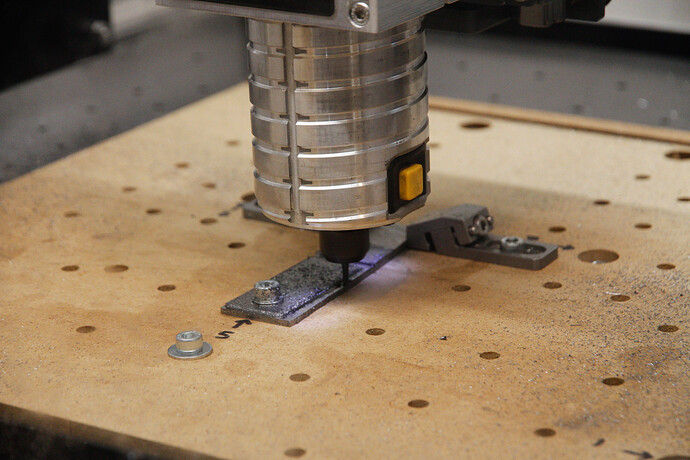
First time attempting Steel, so I used a mini 2.5mm (0.1’’) TiAlN 4F End Mill, with F360 adaptive cuts. Which was slow and conservative but hey I only had one end mill.
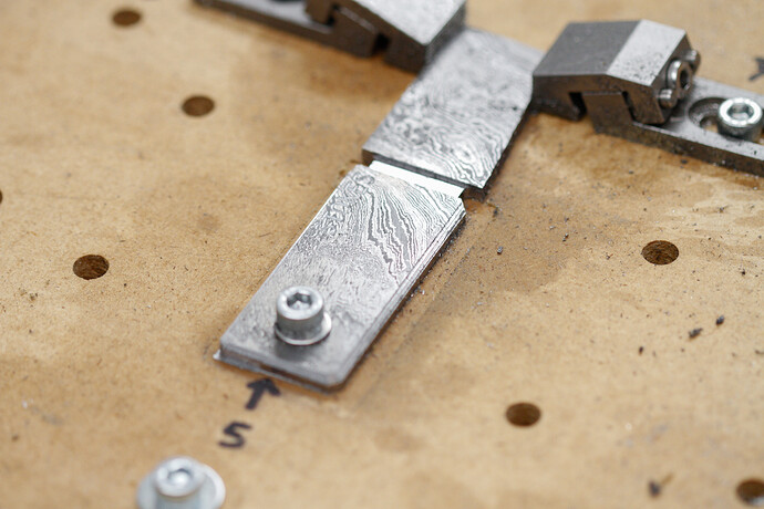
Work holding was pretty difficult, there’s probably a better way to do it. I predrilled a rough hole where the opening would eventually go, and bolted it, with tigers to clamp the stock at the rear. In total there were four operations, two on each side.
I liked the step textured contours/chamfers so I left them in as machined.
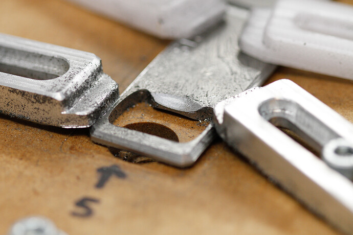
Used a ball the inner chamfered surfaces. Again a slightly janky all hands on work holding, I’m very suprised I didn’t break an endmill or a clamp 
Tab to help with work holding, which I just cut off afterwards and used as a flat surface.
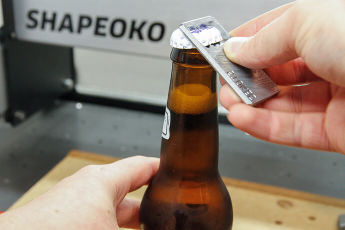
And of course, the most important test, does it work? It sure does!
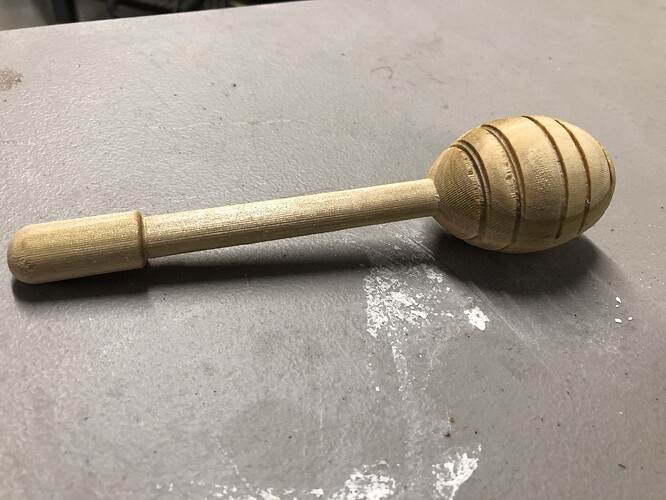
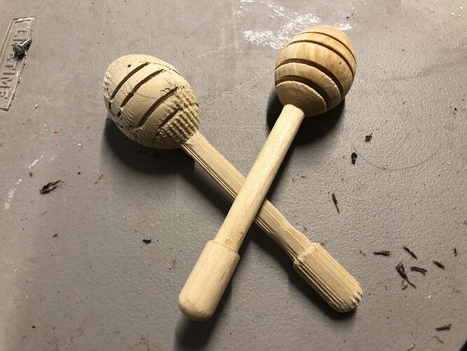
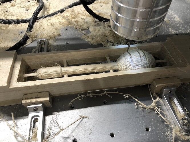
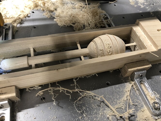
Here is my take on a honey dipper. It came out a little oblong but it has most of the features to pretend to be one. It was my first 2 sided part, which Meshcam helped out a lot in with its automatic handling of the bottom. The first attempt cut a lot better but ultimately failed due to bad placement of the tabs so it broke loose at the end and wrecked. The second attempt had the stringiest cuts ever, both were using poplar glued together.
I used Meshcam for the main geometry and used Carbide Create for stock setup (locating holes, and eventually some relief so the router doesn’t crash with the stock as it gets lower) So it was probably a bit batch of over complicating things. Was trying to steer away from Fusion after the nerfed everything.
Finished and glossed up with some polyurethane
Finished and a failure (failure was the one that cut so much better)
Need to get better at setting the Z without the touch probe, this was too tall to do it and those tabs ended up really thin.
Finished but with some left over fuzz from the stringy wood in this cut.
See the uncut video on Youtube
Top Side: https://youtu.be/fQdvlY4M5gI
Bottom Side: https://youtu.be/uZrZLeCFd3c (possibly still uploading)
I am trying to get the project uploaded on Cutrocket, but it does not appear to like to upload STL files, or Meshcam’s mcf files, or to switch from Draft to Publish lol. I will add the link if I ever get that sorted.
Here is the CutRocket link hopefully for if I ever get it sorted out lol
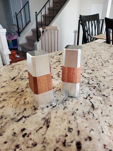
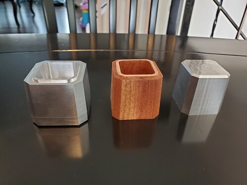
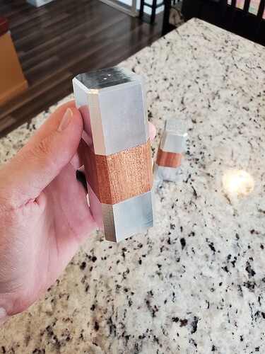
Here are my sapele and aluminum salt and pepper shakers. Each one has 3 parts with 2 operations on each one. The second op required a dedicated fixture for work holding.
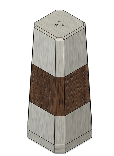
Everything was designed in Fusion 360:
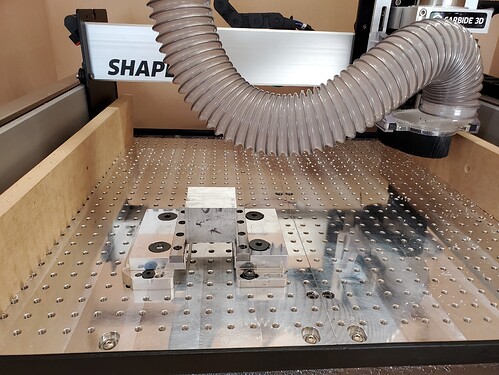
All the aluminum parts are cut from 2" bar stock held in a SMW mod vise (I can’t recommend this setup enough to people who cut metals):
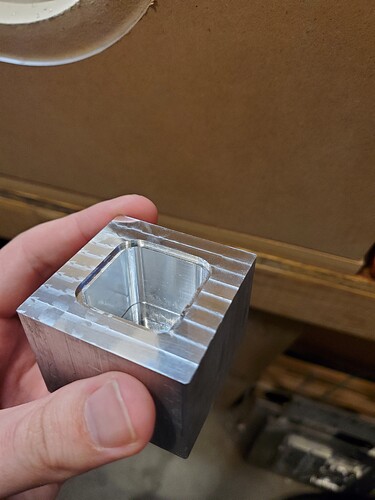
The tapered design necessitates that the inside is cut first and then use a fixture to hold it for the second op. Here is what the top looked like after the first op:
The fixture for the second op is designed to hold each piece from the inside using some mitee bite fixture clamps access from underneath. I was able to make this a very good fit. Pulling the part off would cause suction followed by a very satisfying pop when it came off.
The fixture was made using the same 2" bar stock as the parts. In the future I will be making my fixtures from stock that is larger that the stock used for the parts. The part before the second op overhangs the fixture on all sides and it must be attached before putting the whole assembly in the vise. This makes it difficult to set zero off the fixture. Here is a view midway through the second op on one of the top pieces:
I haven’t cut wood on my machine in a very long time and I had forgotten how forgiving it is when compared to aluminum. I use a 2 flute square and a 2 flute ball end mill to cut both ops. I still don’t like cutting wood because of the dust but I did enjoy how well the sapele machined. It required very little post processing to get it ready for the clear coat. Sapele is a beautiful wood that has a little bit of a shimmer to it when you clear coat it.
To rough out all the aluminum parts, I used mostly adaptive strategies with a 6 and 8mm single flute from Datron. I highly recommend the 4 in 1 single flutes from them for anyone cutting metals. They are very well balanced unlike most single flutes and therefore I can run them at my max RPM of 24000. They also leave an excellent floor finish compared to other single flutes. They are pretty spendy though. My 24/7 reliable roughing recipe for my 8mm tool is 0.03" DOC, 70% stepover, 24000 RPM and 72 IPM (0.003" chipload). For the tapered sides I used an 8mm single flute ball end mill from Datron. I did not like this tool. It is not balanced like the rest of my Datron tools and since it is so large, it cause a lot of vibration. I was able to get it work alright by reducing my RPM to 16000. I will probably go with a 2 flute ball in the future. For the holes in the top I used the smallest end mill I have ever used. A 2 flute 3/64" made by some random company that I found on Amazon. I was worried about breaking it so I used the recommended feeds & speeds from a similar tool made by Harvey Tool. It ended up working just fine. Still gave me the butterflies when I pushed resume after changing to it.
I am really happy how this turned out. The clear coated sapele looks great with the shiny aluminum. They feel great to hold because of the weight. I bought some rubber plugs from Amazon (https://www.amazon.com/dp/B08QCPDPBP) for the bottom and they work great. The whole project was a total of around 10 hours of machining. Here is a view of all the parts and a closer view of one of the shakers:
Here is the CutRocket link:
I can’t get CutRocket to save the Fusion 360 link so here is the zip file of the f3d file.
Salt and Peper Shakers v15.zip (632.1 KB)
In fact, I can’t get it to show the description either.
Disclaimer right off the bat. I’m away from my machine for the past month or so, I made this a while ago as a way to make use of my R-1/16" ballnose bit.
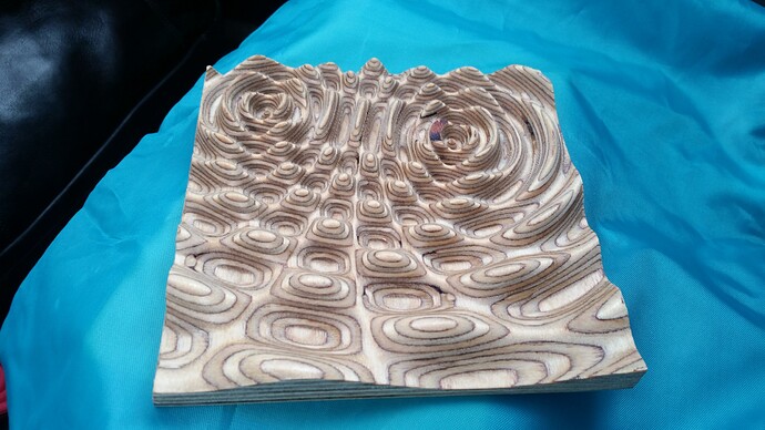
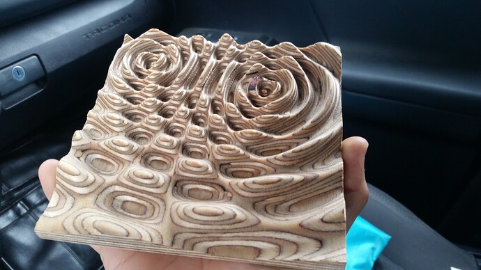
Water waves trivet
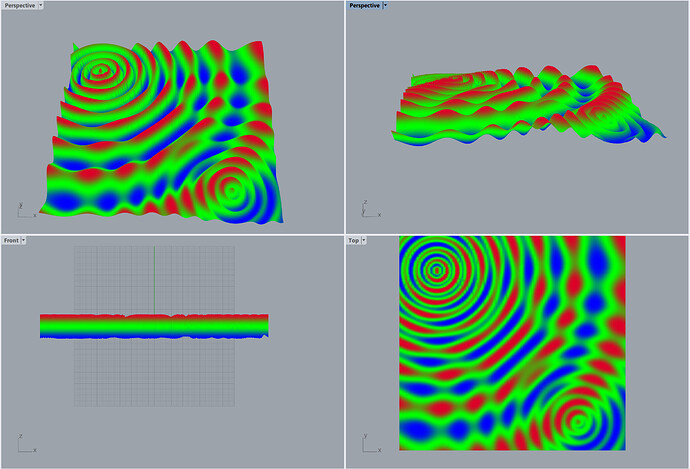
So this project was the first Rhino project I’ve completed from scratch that wasnt from a tutorial/youtube video. It started as an attempt to model the double slit experiment from physics class, it wasnt until I added the coloured gradient on the amplitude that I had the idea to bring it the shapeoko.
Rhino is an artistic modelling program which excels in organic shapes/curves. It’s used in architecture a lot. The final model was slightly different than what is pictured below, I must have changed it a after the stl. export.
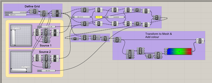
Grasshopper is a very powerful extension for Rhino that can generate incredible patterns algorithmically. Below is the visual code i used to generate this shape. The two point sources were weighted differently to make the pattern a little less symmetric You can see in the bottom left photo above that the peaks are all the same height, this would mean there is no friction or radial energy loss as the waves propagate, HUGE violation of the laws of physics. But this was necessary to hold the hot pans flat, sorry Newton  .
.
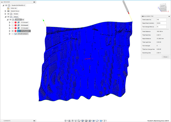
The final model measures 150mm x 150mm x 18mm. It was made of 19mm 12ply Baltic birch plywood. It took 10 mins for the roughing pass with a 1/4" endmill and 3 hours with a R-1/16" ballnose with a 0.5mm stepover. As you can see there seems to be variable step overs in the F360 tool path below, I don’t understand why some areas had more dense step overs but it didn’t hurt anything just took a bit longer.
Once complete I gave it 3 coats of Circa 1850 tung oil as that was the only finishing I had available that stood the slightest chance of standing up to the high temperatures fresh off the stove top.
You can see in the photos that there was a void in the plywood and unfortunately the upcut bit sent that piece flying in the abyss of sawdust and wires behind my machine.
I feel the plywood added a really cool topographic feel to to all and I’m very pleased with it on the whole. It protects the table well and holds up to the heat with no visible signs of wear or degradation. If I were make a larger piece for wall art I would make the waves a bigger and more sweeping, completely forgoing the plywood for a nice grain with with real character.
Cut Rocket available here
What do you think!?
So many great entries, voting is going to be interesting!
Let’s see if we get a couple more last minute entries by the end of today
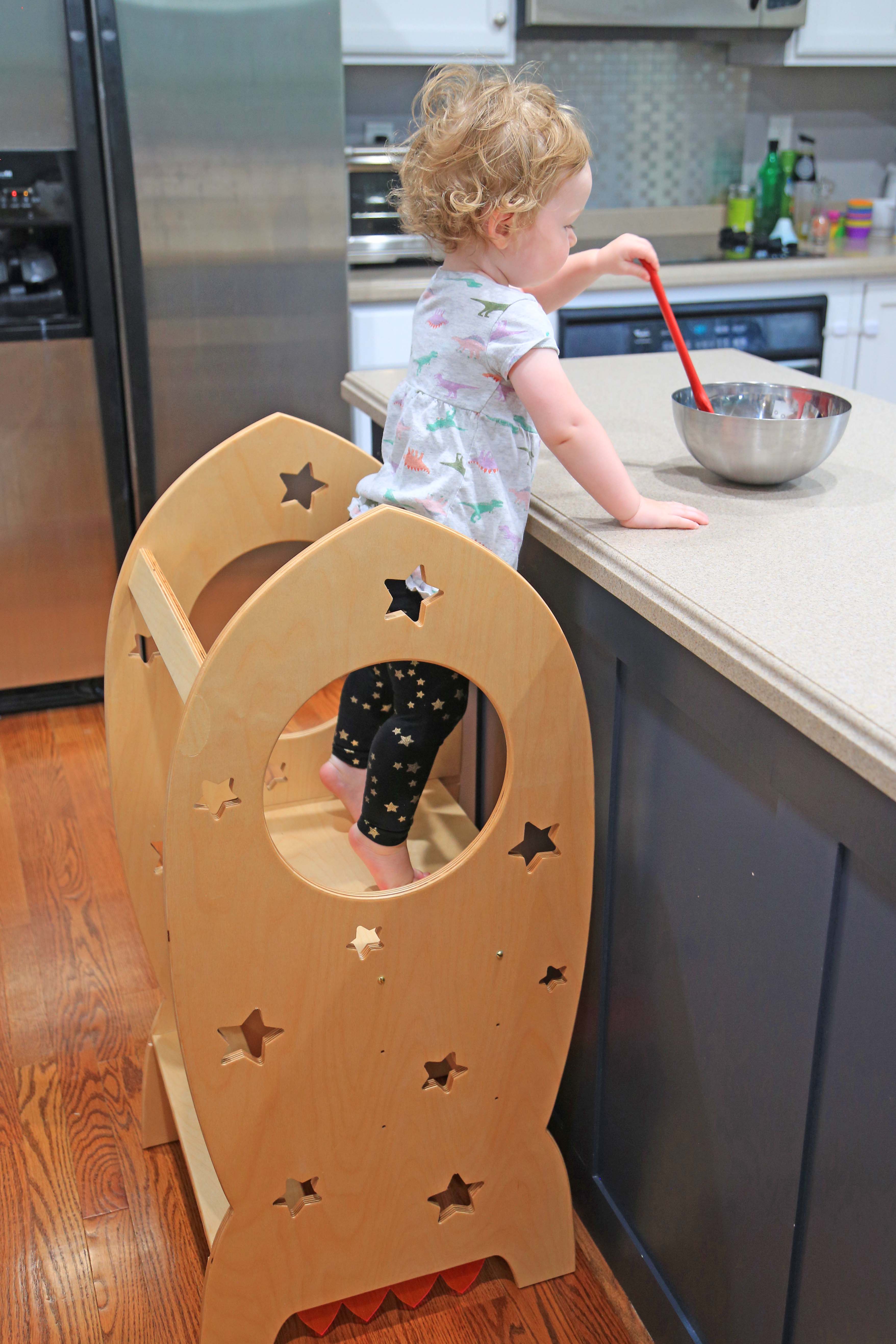
Here’s the kitchen tower we made for our toddler. She loves climbing things and always wants to try to help, so we wanted to make a little rocket step stool with some safety bars for her to be more involved in the kitchen.
This was the first piece we’ve made larger than the XXL bed, so I worked out some indexing holes with a wooden dowel spaced the right distance to go into some of the T-slot wasteboard pieces. The material is 5/8" baltic birch plywood.
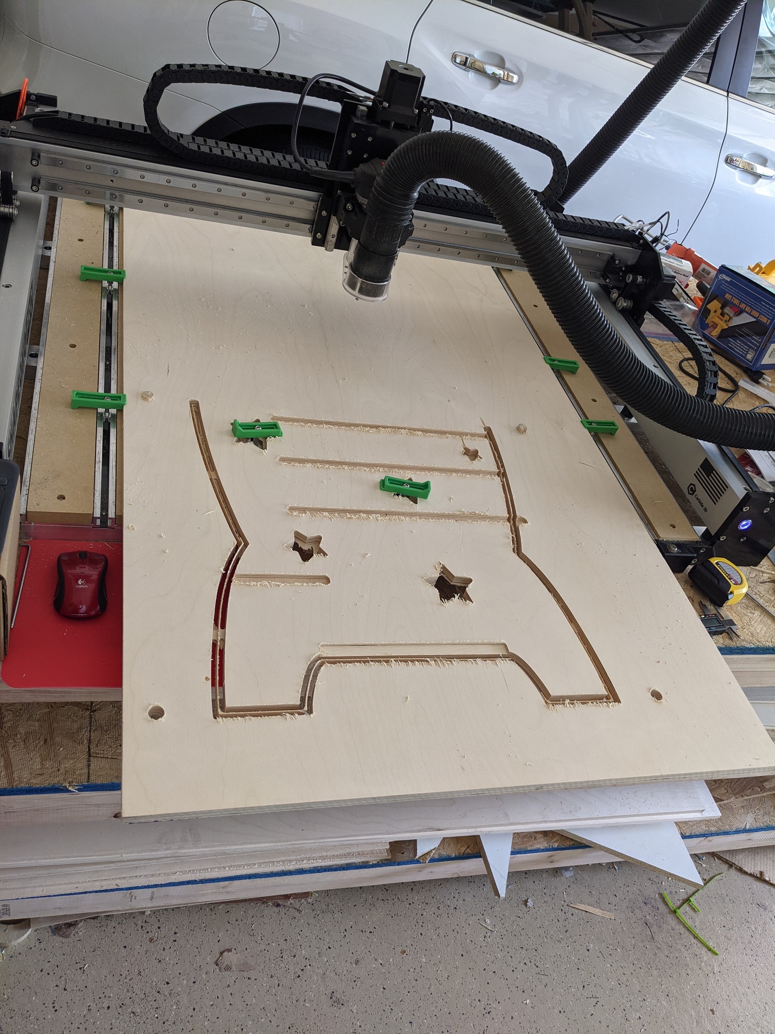
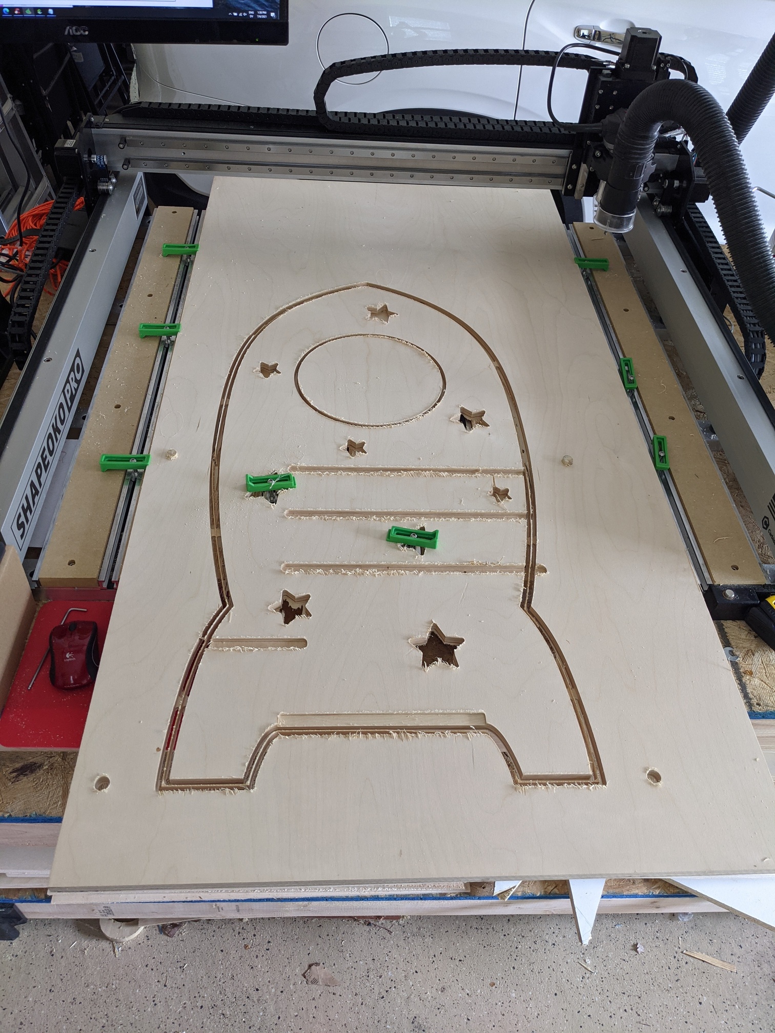
This post was helpful in making me realize how to do the outline when breaking it apart into two operations, although I probably made the section a little wider than necessary and there was a tiny strip of material in the middle of my contour. I set up the indexing holes and broke apart the sections in illustrator because it’s what I’m used to. My old version of illustrator (from before they started making you pay monthly) doesn’t seem to let me export as .svg, so I still have to remember to scale everything in CC. I’ve started just putting in bounding boxes with easy dimensions to make scaling them easy, and that helped line up my indexing holes anyways for the two sections.
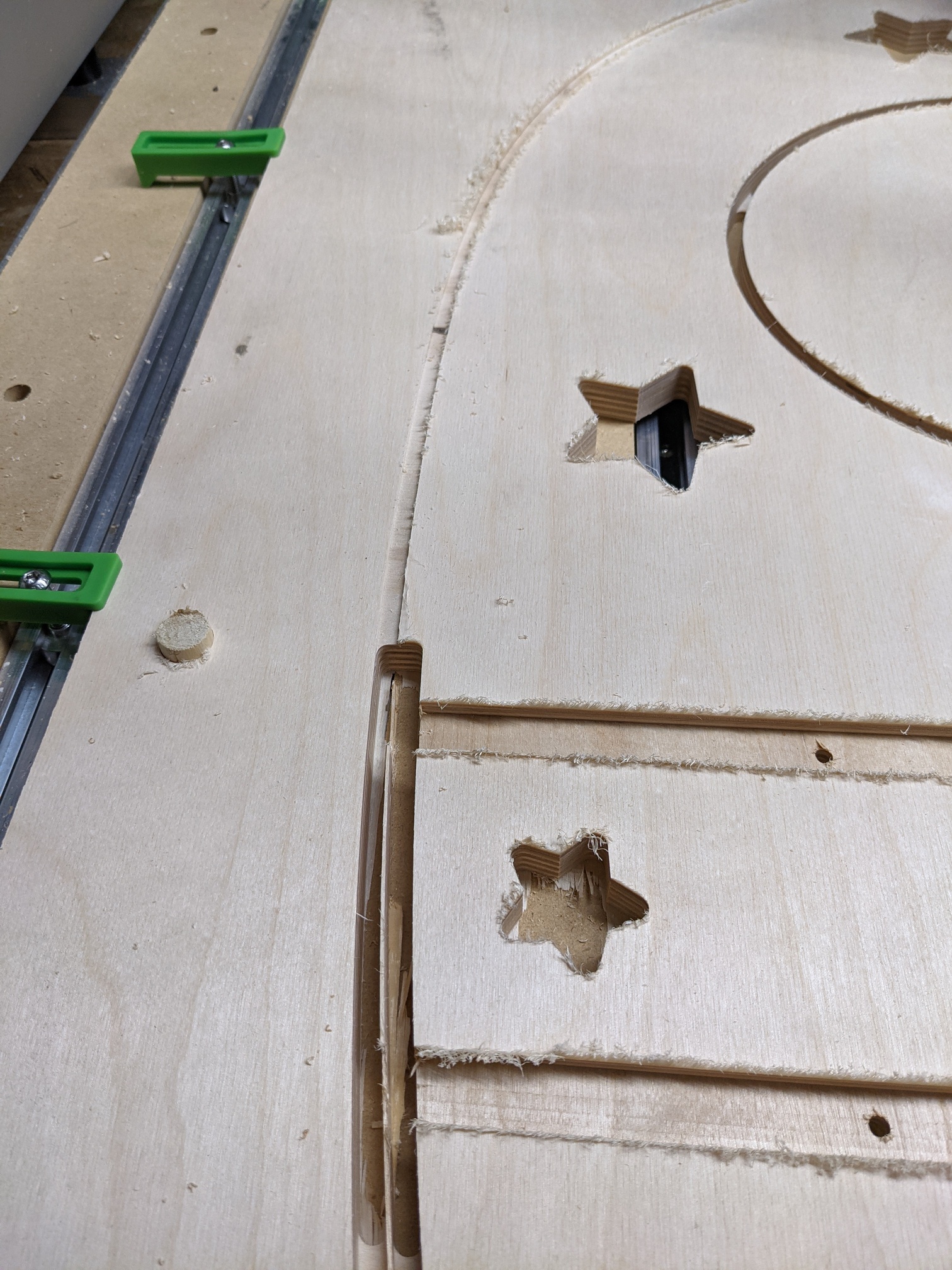
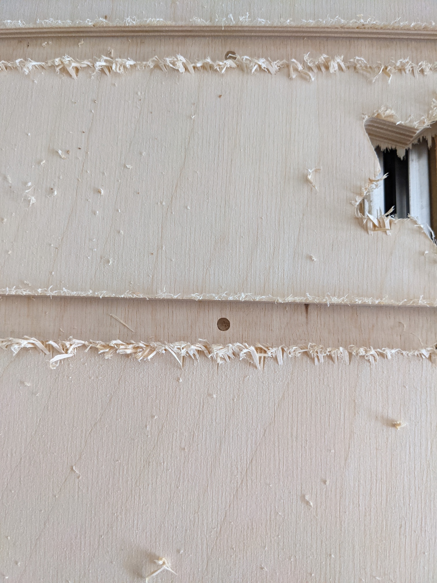
I had some issues with some of the gcode due to having an old version of Carbide Create (huge thanks to @Julien and @fenrus for helping me out so quickly!), and left the machine on overnight because cutting the first piece took way longer than expected. Some how the machine lost power between the two operations on the second side of the tower the next day. I had to rehome the switches and was worried it might mess up my indexing, but it still lined up incredibly well. The below photo is the first couple passes of the outline on the second section meeting with the outline from the first section.
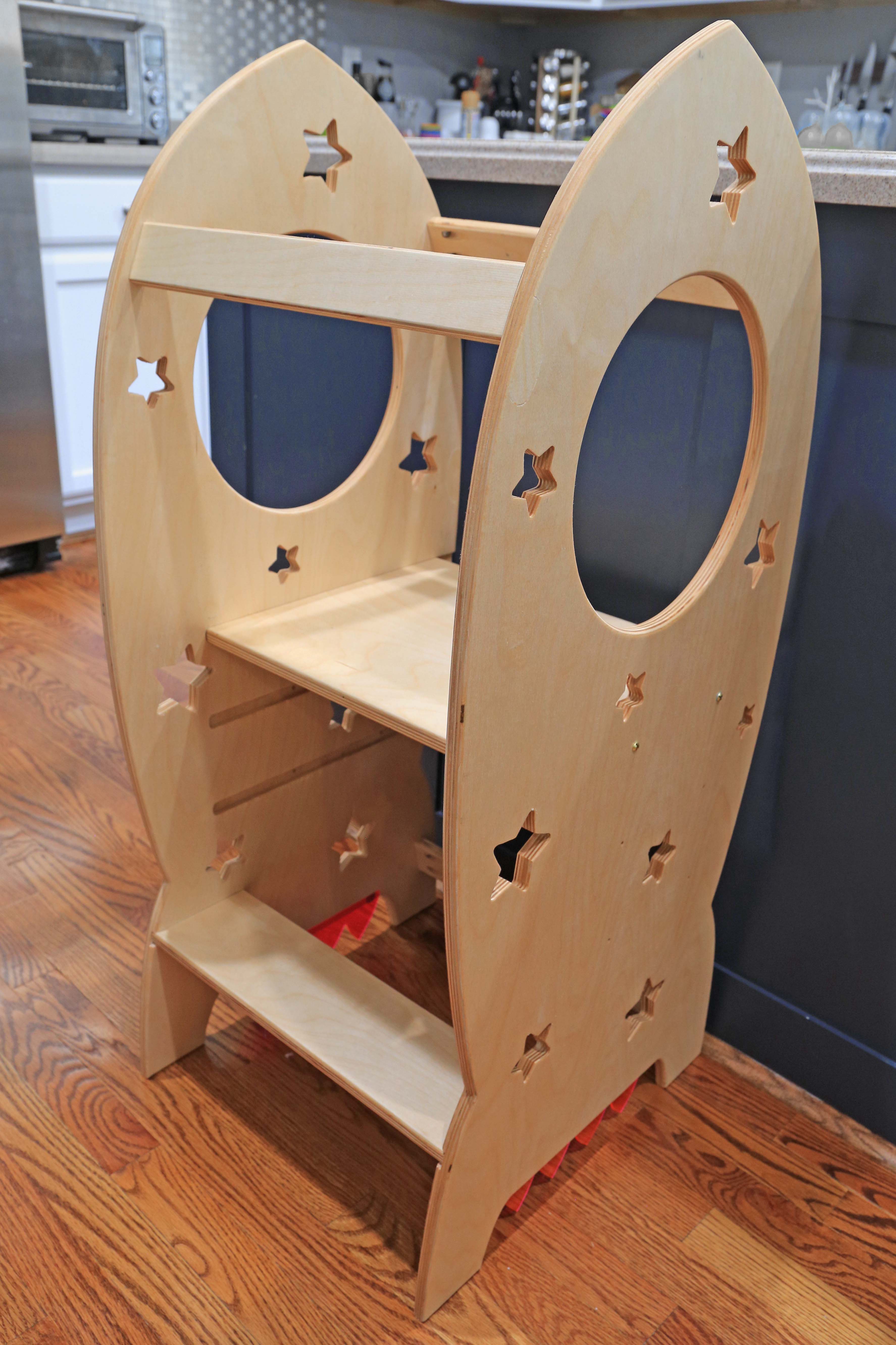
I designed the sides to have a slot for the foot step and three slots for the main shelf so we can adjust it as she grows. I also added holes in the main shelf slots so they would be the same distance apart so the threaded inserts I used in the shelf would line up with the holes for each level. If I was doing it again or had a full plan when I started, I’d have made shallow pockets for the other braces so it would be easy to line them up when I joined everything together.
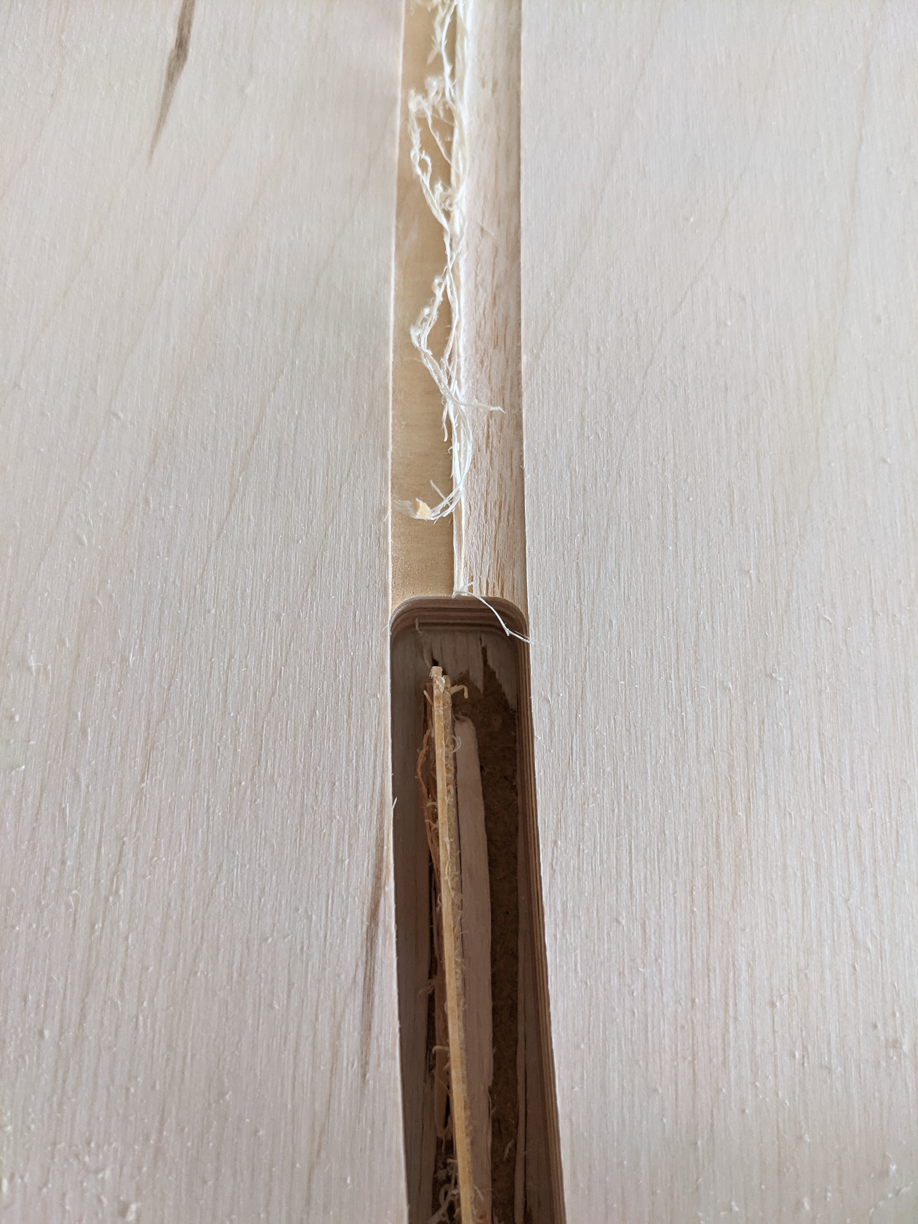
One of the side pieces chipped out much worse than the other on the slot pockets, and I’m not sure why or what I could have adjusted to make it not as bad. The first one just had some fuzzies which sanded off easily, the second one had significant flakes of the whole top ply ripped back. It was on the inside though, so ultimately not really noticeable in use.
The braces are just 2" wide pieces cut to 15" of the same plywood, and the shelves are 12.5" and 4" deep by 15.5" wide. We put all the braces and the foot shelf in with pocket holes. There’s a shallow pocket in the bottom for the fluorescent acrylic exhaust flames, which look way brighter in real life (full disclosure - I cut these on my laser because it was quick and easy).
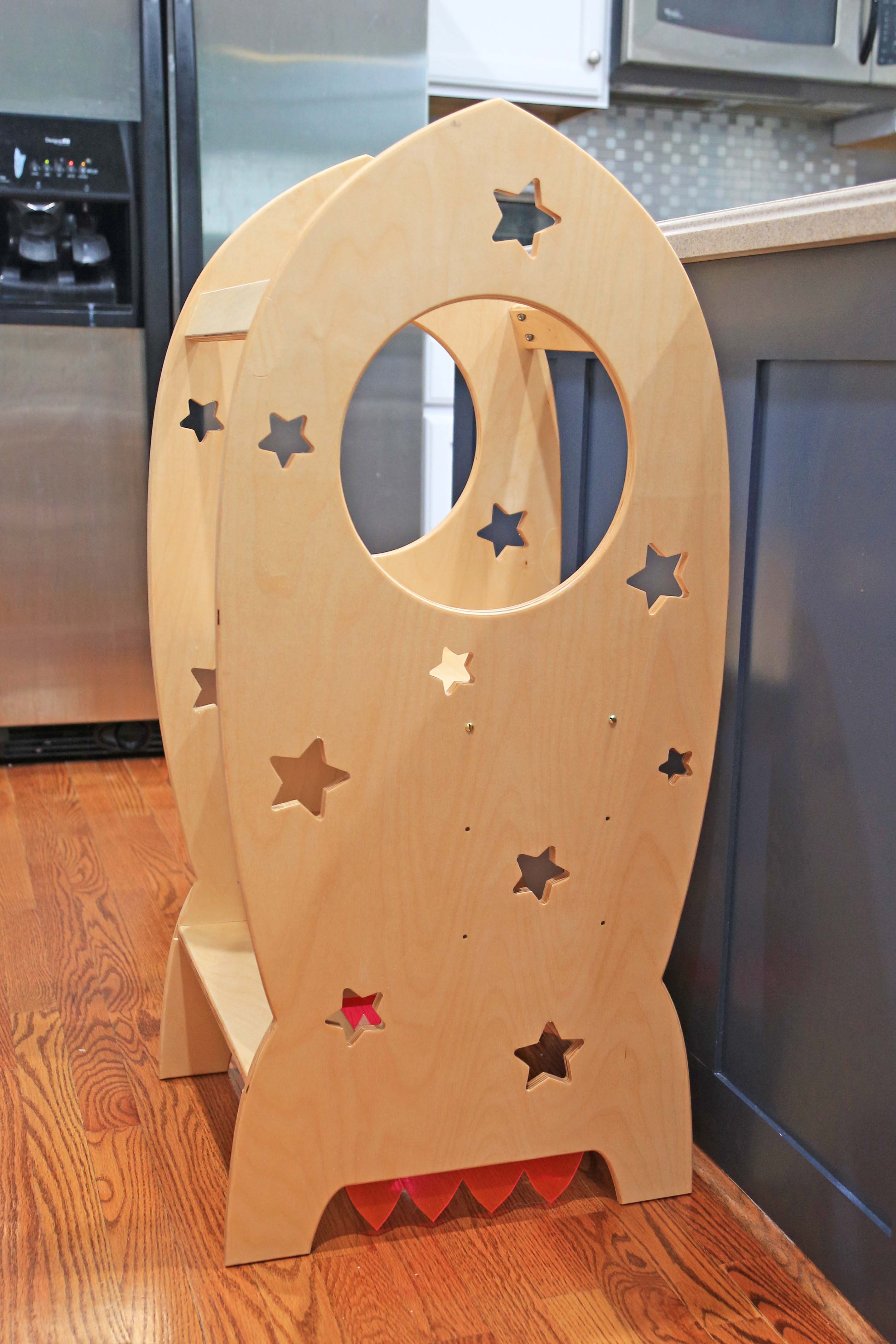
I fussed a lot over the height of the step shelf and main shelf and worried about whether she’d be able to climb up it quickly, but I shouldn’t have been surprised that she was climbing up on her own in about 5 minutes and trying to climb on the counter not much later.
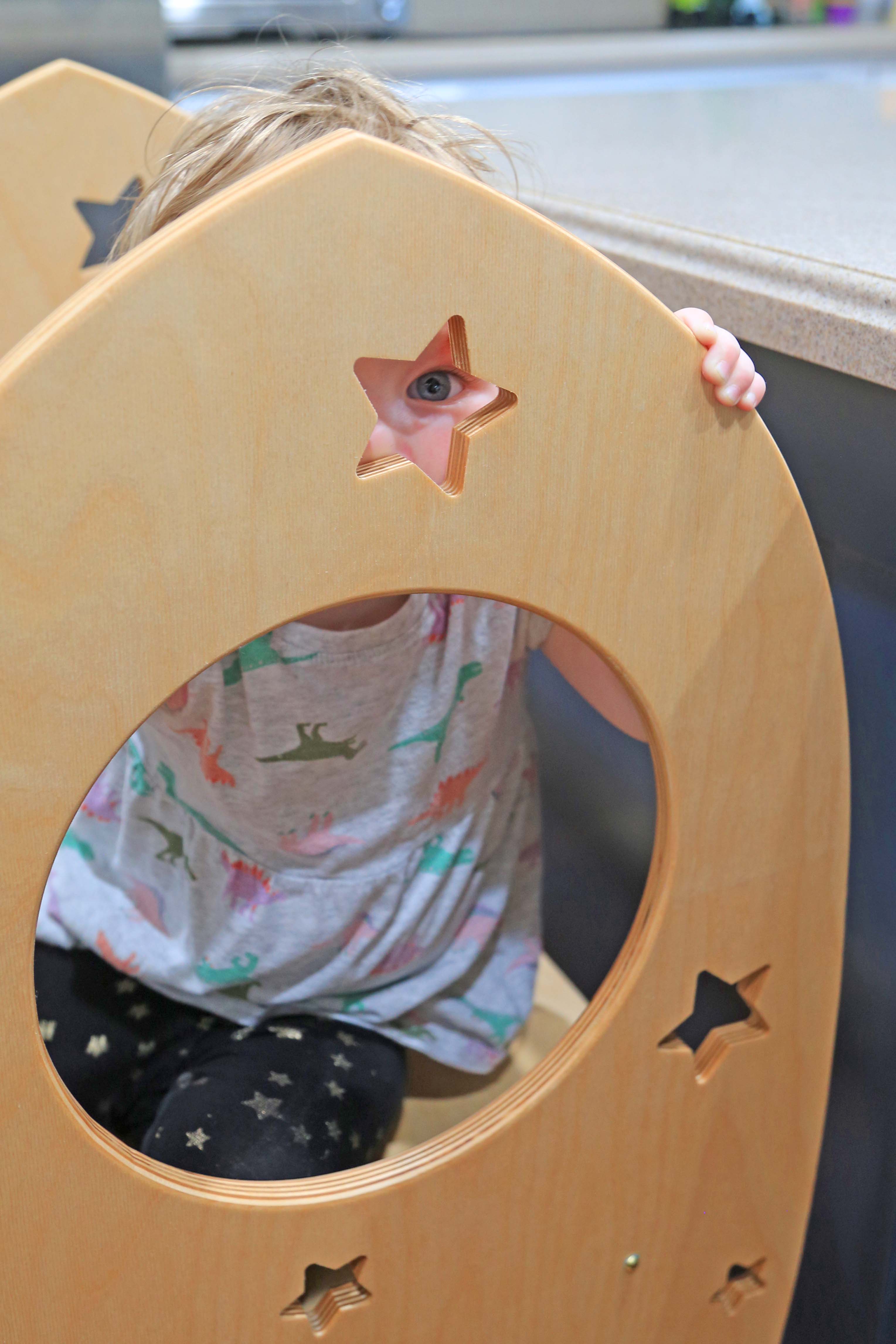
She seems to like being able to climb up to reach the counter well and seems pretty safe while she’s up there, so in that regard I’ll count it as a big success! Now we just have to do better about keeping our island cleaner and letting her ‘help’ with more things - we’ll see how that goes 
I added everything to cutrocket, but it’s only letting me save it as a draft, not publish it. The only warning I see is that I need to upload at least one design file. I have three .c2d files uploaded - does it need a F360 files and those don’t count?
It looks like I’m going to really bump up my effort for these contests. I’ll grab first eventually though 
Let me start by saying the end result is not so much the entry here. The process is the real star of the show. I only had about a day to do this project so I put the “rapid” in rapid prototyping.
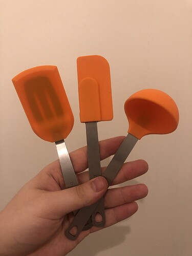
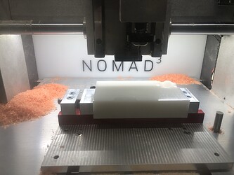
What was the prompt? Well, I have a really nice olive wood spatula that has a nice curve on the end for right handed folks. My wife is left handed. As with many things in the world, she was left wanting for a left handed version. You would think the prompt might be “make a left handed spatula” but I have no exotic woods beautiful enough for the wife, nor do I have a machine large enough to do it in one go. I just got a nomad 3 about a week ago.
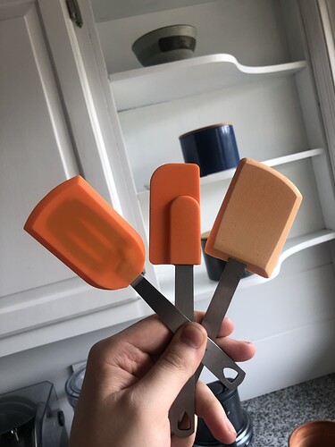
So let’s adapt. The wife has a slew of tiny silicone utensils that she absolutely adores. These tools are rare enough in the standard variety, there’s no chance someone is making a miniature left handed silicone spatula…that’s something I can work with.
I hopped into fusion 360 with my calipers and a deconstructed mini utensil that was starting to rip anyway, the wife wouldn’t miss it. I modeled up the handle first, a long thin piece of flat stock. Then proceeded to model the spatula head, the piece that would be made of silicone.
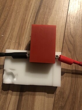
Remember how I said I got the nomad around week ago, yeah…I have no idea what I’m doing. I’ve got some blocks of machinable wax that will be my go to material for prototyping. Apparently it cuts like butter and I can recycle it easily. I thought to myself “Self, you’ve got a 1” thick block of this wax but you only need a ~6mm slice.” so I did what anyone in that position would do and threw together a hot wire cutter with my bench top power supply, a bit of nichrome wire, and a block of HDPE.
It worked surprisingly well BUT I learned that wax likes to reweld as you cut it so that idea was shot. Still, it’s something to figure out in the future. For now, we would just deal with using a less than ideal piece of stock.
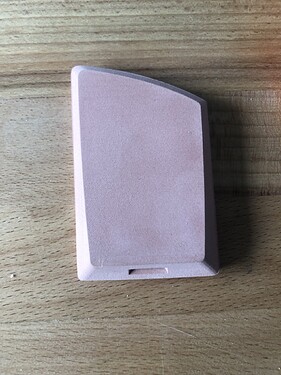
Aaaanyway, I had the thing modeled and wanted to do a test run. Cut out the shape from a piece of material the wife could hold, beat up a bit, and ideally sign off on. I have some renshape which I’ve never used. I figured now was as good a time as any (that stuff is amazing by the way). I got the model cut and into the wife’s hands where she proceeded to run it though the corners of our pots and pans. She decided the corner radius “needed to be fatter” and the angle on the front edge “needed to be flatter”. Other than those two issues, she absolutely loved it.
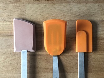
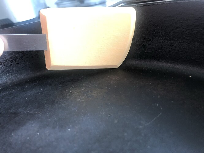
(renshape spatula: first attempt. Top left corner too pointy, front angle too steep)
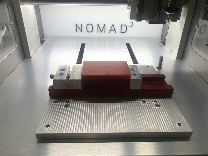
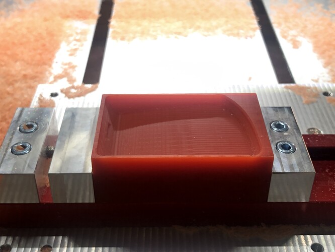
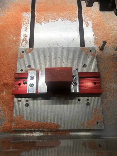
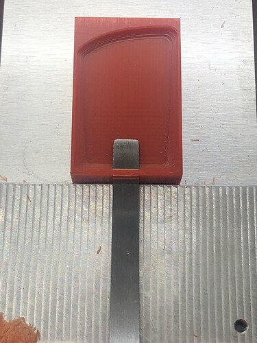
With that feedback in hand I quickly modified the model. I didn’t have time for another test piece though so I whipped up the mold that would be cut from wax and crossed my fingers. (This is another huge lesson learned: You can get much cleaner lines and edges when cutting away stock leaving your final shape as opposed to cutting the mold into the stock. This is obvious in hindsight but it was a real facepalm moment for me)
The wax also cut beautifully, I cannot wait to get my recycling operation up and running for it. So with the wax mold in hand there were two things left to do: quickly mill the reinforcement plate and overmold it with the food safe silicone I have on hand.
wax: highly recommend
Surface finish: bad. Meh, cut me some slack I’m new here
I hit the z axis limit switch because of my retraction height doing this operation
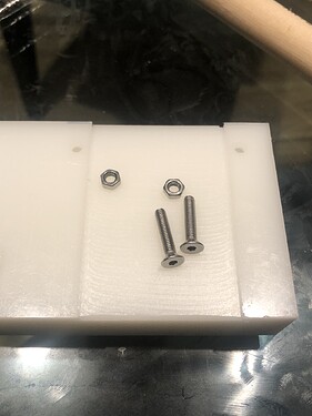
The handle fits perfectly. I just cut the little wax bridge, I’ll mill a removable one eventually.
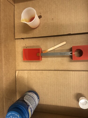
With those two items I had two issues: I have no material to make the reinforcement out of (I only have ¼” aluminum with I’ve never milled before…and I don’t have 12 hours to wait for the silicone to cure.
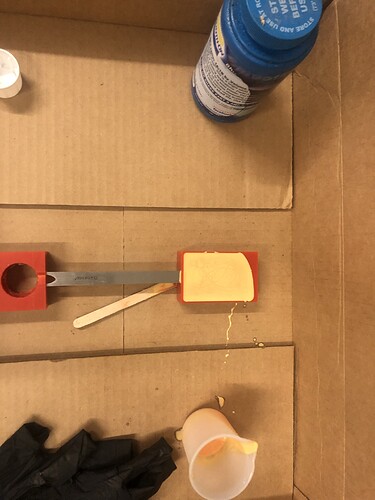
So my entry is going to be a quick cure resin proof of concept. If it looks right/feels right, I’ll get some proper thin plate stock in and I’ll obviously have to buy some orange silicone dye.
Orange dyed Smooth-On smoothcast 300. Cures in ~12 minutes
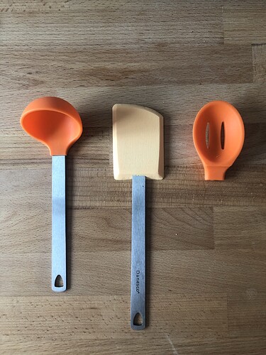
Almost looks like it belongs there
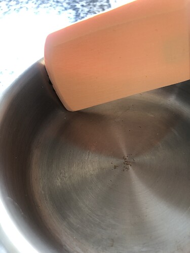
Passed the pan curve tests
The wife has requested I keep the sheet metal and silicone needed for these tools in stock. Looks like she’s really leaning into the “You can make real stuff instead of just 3d printed junk now!”
TLDR Lessons learned:
- It is easier to mill a final shape than it is to mill the mold for a shape.
- There is a z height limit that while you may not hit with the model, you can trip with the retract height…whoops.
- Validation is worth the time/effort.
- I need to work on my finishing strategies, they suuuuck.
- I need to start charging my wife for design time.
Overall this has been an incredible introduction into the world of CNC. I can crank out designs so much faster and easier than with my form 3. Now I can keep my wax stocked up and essentially iterate for free. The process will be: iterate designs in recyclable wax, validate injection molds in high temp form resin, mill final injection mold from aluminum on the nomad.
For items that will not be injection molded I can simply use the wax as the model and cast silicone molds, again recycling the wax.
Apologies for absolute wall of text/photos and the non-kitchenware related tangents. I’m just silly excited to finally jump into this  It’s going to be a good time.
@HeuristicBishop: I enjoyed your write-up, 100% what these challenges are all about!
@DrEigenbot pretty cool entry! but now I’ll have to add a rule to not include cute toddlers in the pics, it’s not fair to other contestants 
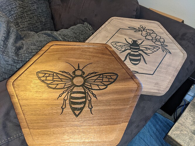
Fancy Walnut Bee Charcuterie Boards:
This is my first major project since replacing my control board with a Duet 6HC board:
Still a few minor kinks to work out with my macros, but I am really loving it. Getting used to a new work flow has not been without its challenges.
Challenges:
- Hurricane Elsa coming by Tampa Bay Florida has made the weather way too humid for applying the finish on the second board. Hoping to complete that tomorrow.
- Sanding inside the V-Carve patterns was rather difficult till I found these: https://www.amazon.com/gp/product/B0019N4TPY at my local Woodcraft store. Only complaint is that the abrasive wears off the edge rather quickly. Probably because the sand paper is bent at too extreme an angle.
- Ran into a bug in the old version of CC that made Gcode my Duet did not like. This caused the the rapids to carve through the material and forced me to resurface the piece and start over. Advance VCarve Did Not Retract During Rapids - #8 by CthulhuLabs luckily it was fixed in a newer version of CC.
- Because I had to start over I ended up having to try to pick back up zero on a hexagon. This proved tricky till I realized that with my Duet I could make a custom Macro to have my BitZero pick up the outside corner of my Carbide Corner Square and put the zero at the inner corner. With that I just butted one of the edges of the hexagon up against the bottom edge and the corner against the other.
- One of my macros worked great in my testing, but crashed my endmill into my first attempt because it was using absolute positioning for one of the moves rather than relative. It was a simple fix and kind of a bone headed bug.
I have uploaded the general design files and one of the V-Carve patterns to Cut Rocket but cannot seem to publish them for some reason. The second one unfortunately does not have a compatible license, but I will link to where I got it.
