I’m looking for help on how to set my cnc shapeoko machine so that I can just do a plunge hole of 1/8 rather than the way I have it set now as a pocket of 1/8 using a 1/16 but it keeps snapping, there has to be a way
I make crib boards, but I do not use Carbide software. I use inkscape to layout the boards, and MakerCAM to generate the g-code. If you are interested, I could put together a quick tutorial.
There are others here that use Carbide Create and also make crib boards, and they may be able to help you if that is the work flow you prefer.
What material are you cutting?
What tooling are you using?
At what feeds and speeds?
1 Like
That would be awesome if you could do that I have never used those programs tho
CNC Machines do not make good drill presses. The problem is if you use drill bits they are designed to run at a much slower speed than a Dewalt or Makita/C3d router can run. So cutting a pocket with small bits is still hard even if the router RPM is faster for a router bit. I have posted on the forum some carbide drill bits that are designed for drilling cribbage board holes and can handle the faster speed of a router. It depends on if this is a one off or a production job. If the holes are 1/8 (.125") then make the holes .126 and use the 1/8 bit. If this will be done repeatedly then buy some carbide drill bits made for a cnc.
Check out this youtube video. The presenter has his own cnc channel and is selling things so take what he is selling with a grain of salt.

I use carbide drills made for circuit boards, run them at 12K RPM, 0.10" peck (I am probably going to change it to 0.15", but for now, I still have gcode that is 0.10" peck) and 30IPM plunge. I can make 5 or so 4 player boards (533 holes each board) before needing to change the bit.
1 Like
Let’s start with designing a cribbage board in Inkscape. I finally upgraded from 0.9.4 that I ran for years, and the jump to 1.2.1 was pretty big. But since you have never used it, it’ll be no big deal.
Okay, go get Inkscape and install it.
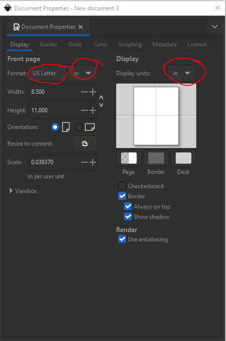
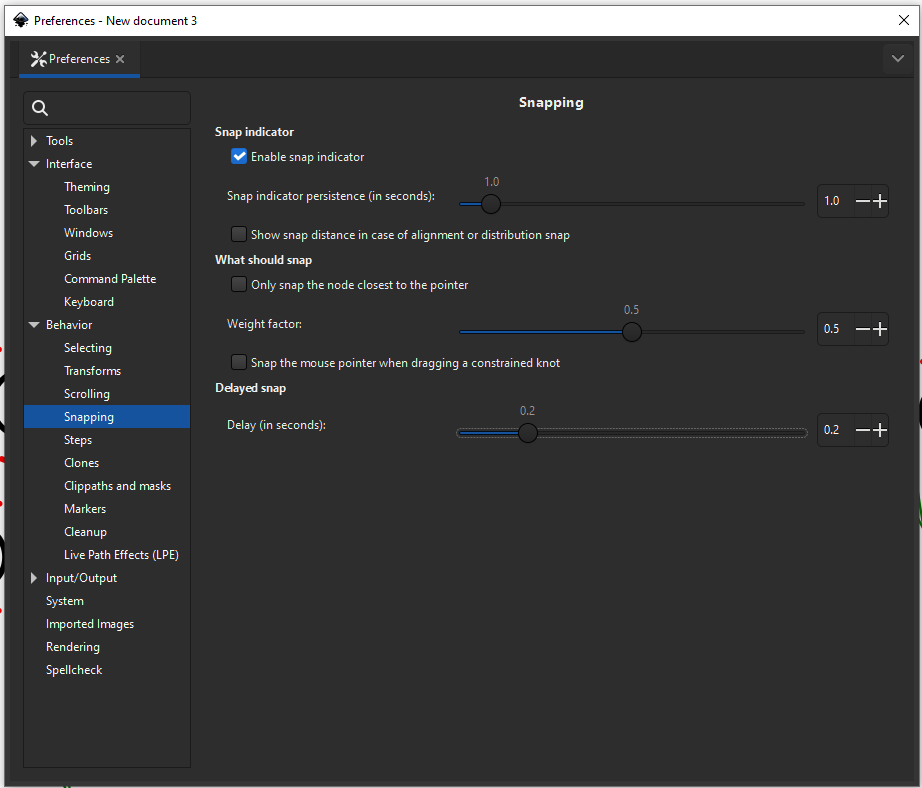
First thing I do (because I haven’t looked to see how to change the default settings) is change the units to inches and the canvas size by going to [File] - [Properties]
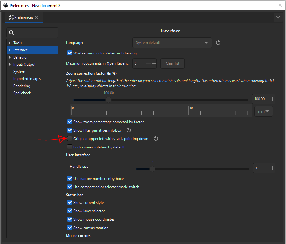
The other thing that needs to be done (but only once, fortunately) is to change the origin from the top left corner, to the bottom left corner by going [Edit] - [Preferences] - [Interface] and unchecking the check box that reads “Origin at upper left with y-axis pointing down”
Now, you are ready to begin designing your cribbage board.
I have used cribbage boards where the holes are so close, the peg heads are wedged up next to each other, and I find it unattractive. I think each peg should have it’s own “space” to exist and not be crowded on the board. So, the first thing you need to do is figure out what pegs you are going to use. Let’s go check out a peg seller. I am going to pick Pete’s Pegs, because I used to buy from the guy who owned the website before he retired. So he sold his website to whoever owns cribbagesupply.com. Anyway, I have no business interest in them, other than buying pegs from there.
I use #15 Columbia pegs for my boards, so let’s take a look at them, shall we?
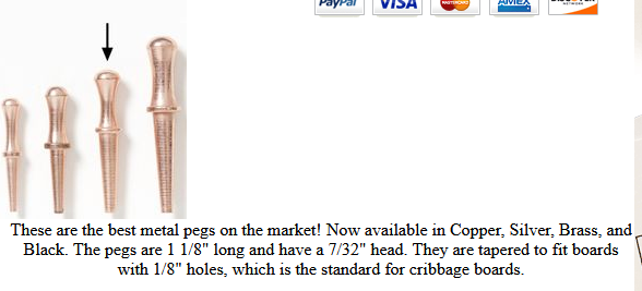
They are made for a 1/8" hole, and they have a 7/32" head. The head is the size we want to design the hole spacing for. That way, we won’t have the pegs crowding each other. This will mainly come into play in the corners, as you will see. I’ll design a “standard” crib board like this, to get you going.
Inkscape has loads of keyboard shortcuts, and while I don’t know them all, I learned the ones that really speed things up when creating arrays of holes.
[CTRL] + G will group whatever you have selected.
[CTRL] + [SHIFT] + G will ungroup whatever you have selected.
[SHIFT] + [Left Mouse Button] will allow you to select multiple objects.
[CTRL] + [Left Mouse Button] will allow you to select only one object that is in a group
There are more, but those are the ones I use the most.
[Continued shortly]
1 Like
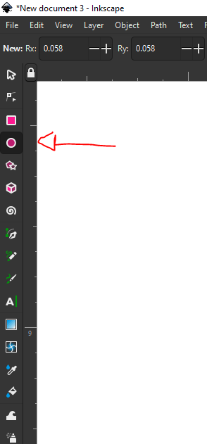
Let’s make some circles. Select the circle icon and make two circles. It doesn’t matter how big they are, because we are going to change them using the dimension boxes after we create them.
Just click and drag and make a couple of them.
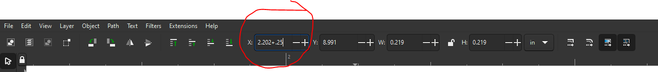
Now, select one of them, and look at the top tool bar. There, you have the X and Y location of that circle,m as well as the X and Y dimension. The dimension is what we are going to change.
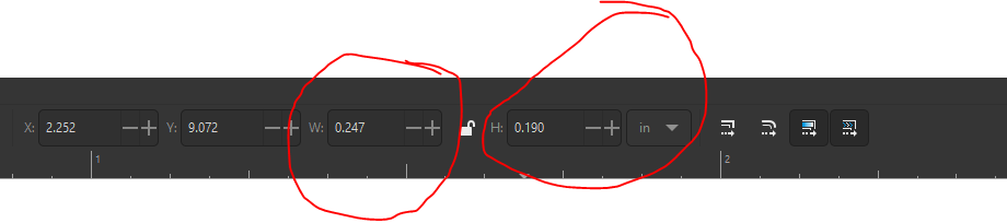
Change both dimensions of one circle to 0.125, or 1/8. Inkscape allows mathematical equations in their dimension boxes, so you could even put “(1/8)+.5” (but not the quotes) and it will resolve to 0.625
Change the other circle dimensions to 7/32 and it will resolve to 0.219.
Now, we need to change the color of the lines and infill. Select [Object] - [Fill and Stroke] to get the fill and stroke tool bar.
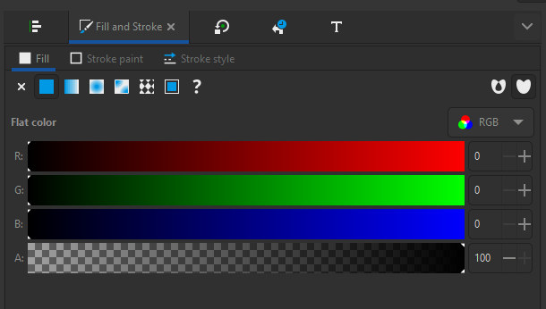
I like the RGB color space, since (at least for me) the colors are just for me when laying out patterns. You’ll see. . .
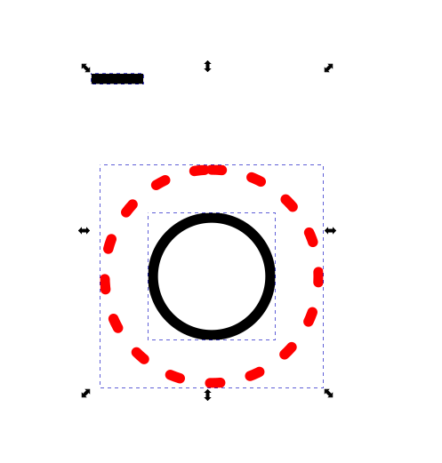
Select the 1/8" circle, then:
Select the “Fill” box, and then select the “X” to remove the fill.
Select the “Stroke Paint” box and move all three sliders to the left so you have a black line.
Select the 7/32" circle, and then:
Select the “Fill” box, and then select the “X” to remove the fill.
Select the “Stroke Paint” box and move the green and blue sliders to the left, and the red slider to the right, so you have a red line.
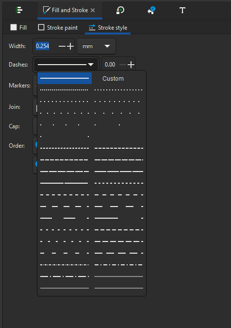
Select the “Stroke Style” box and pick one of the dotted lines.
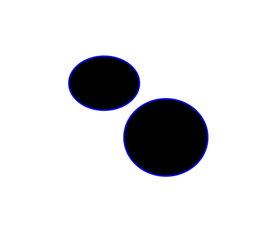
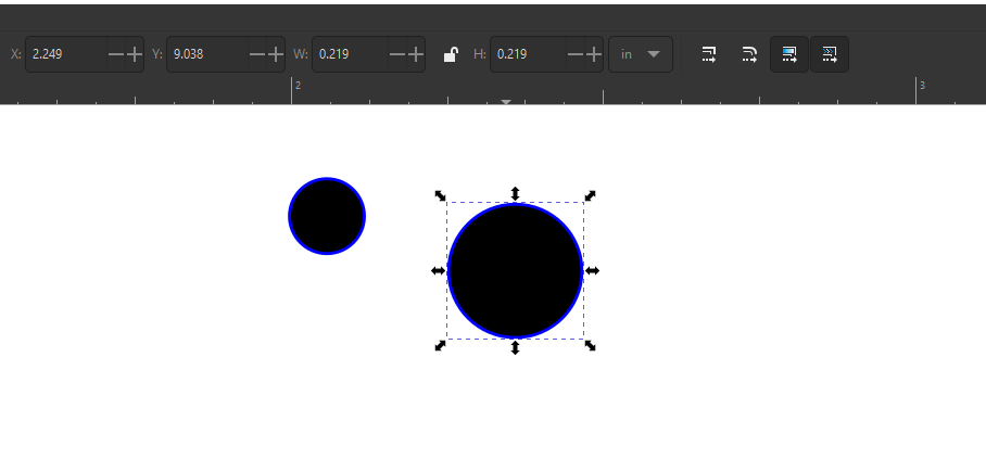
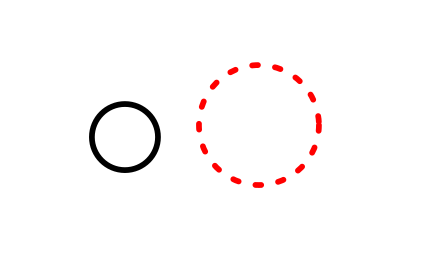
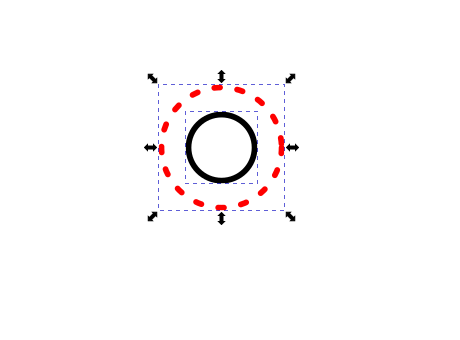
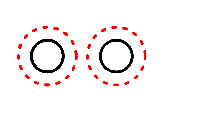
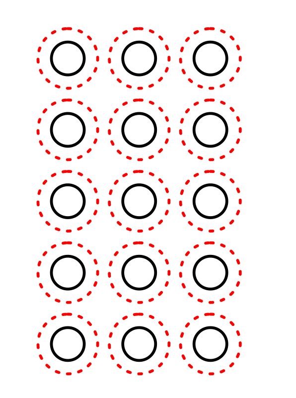
You should now have a 1/8" circle (black solid line) and a 7/32" circle (red dashed line).
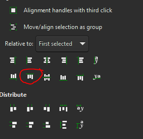
I am going to center the red circle on the black circle by using the “Align and Distribute” toolbar. It’s actually more of a side bar, but whatever. If you select [Object] - [Align and Distribute], you should get another side bar.
I prefer that when aligning objects, I like to have them align to the first object I select, so that is what I have it set to. You can change it to your liking.
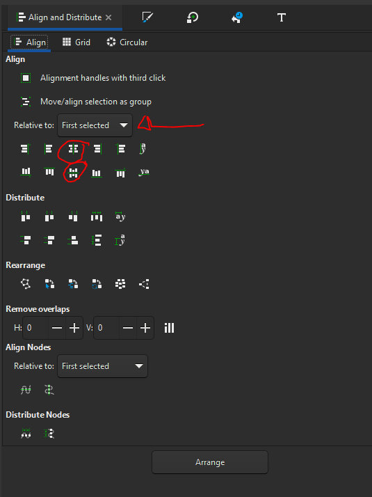
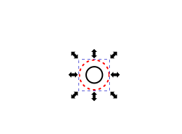
So, we are going to align the big circle to the little one, so select the little circle, then press and hold [SHIFT], and select the big circle. Then click the “center align vertically” icon, and then the “center align horizontally” icon, and viola! Two centered circles.
[CTRL] + G and they are a group now.
[More tomorrow]
4 Likes
Replying. I see a post has to be 20 characters also.
Okay, one more neat keyboard shortcut is this one:
[CTRL] + [SHIFT] + [Left Mouse Button] will allow you to select only the one object you click on that is in a group and add it to the already selected objects you have.
I am going to throw in these two as well, just to cover all bases, but you should know the ubiquitous. . .
[CTRL] + C copies the selected object(s)
[CTRL] + P pastes the selected objects copied
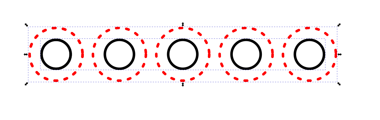
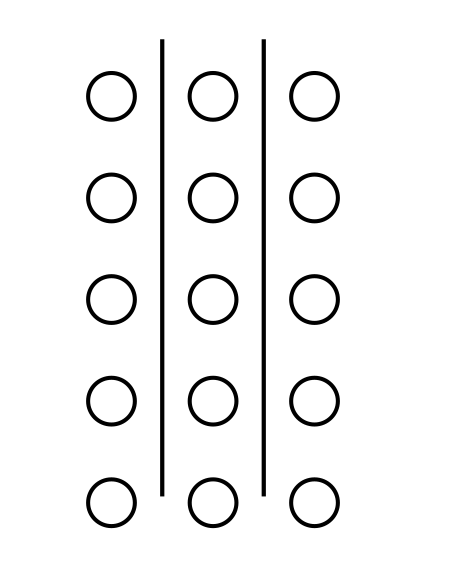
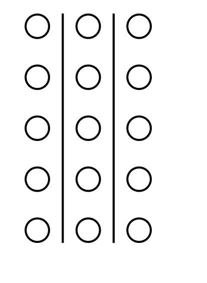
Okay, so now we have a couple of circles. Now the fun begins. We are going to build arrays of 5 holes x 3 players.
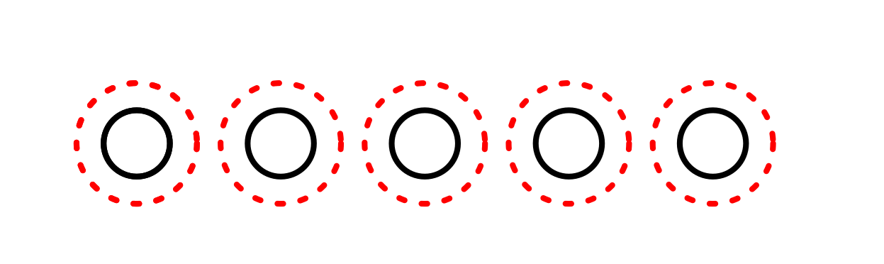
We’re going to select our two circles that are grouped together and do a copy / paste 4 times so we get 5 of them. When you paste, the new object is placed with the center of the object centered on your mouse pointer.
becomes
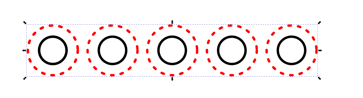
Now, back to hole spacing. Select all 5 of the circle groups, and then center them all on top of each other using the align middle commands from my previous post. It should look like you are back to one circle group again. If you have a mouse wheel, [CTRL] + Scroll will zoom in and out. Zoom in a bit so we can set the hole pitch we want.
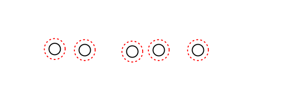
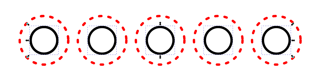
Now, select the top group by clicking on it, and then go up to the “X” dimension box, and add in some distance to space that circle group (and by extension, the holes for your board). We know that the head of our pegs is 0.219", so we are going to add at least that dimension. Let’s put another 0.031" space, to make it an even 0.25", so in your “X” dimension box, click to the left of whatever number is there, and type “+.25” (without the quotes) and hit enter.
You should now have this:
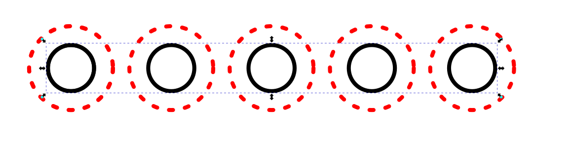
Click on the left group, where there are four more circle groups stacked up, and go back up to the “X” dimension box and hit “+.5” and hit enter. Now you have three circle groups in a row. Do the same thing two more times with “+.75” and “+1” to get the last two circle groups laid out evenly.
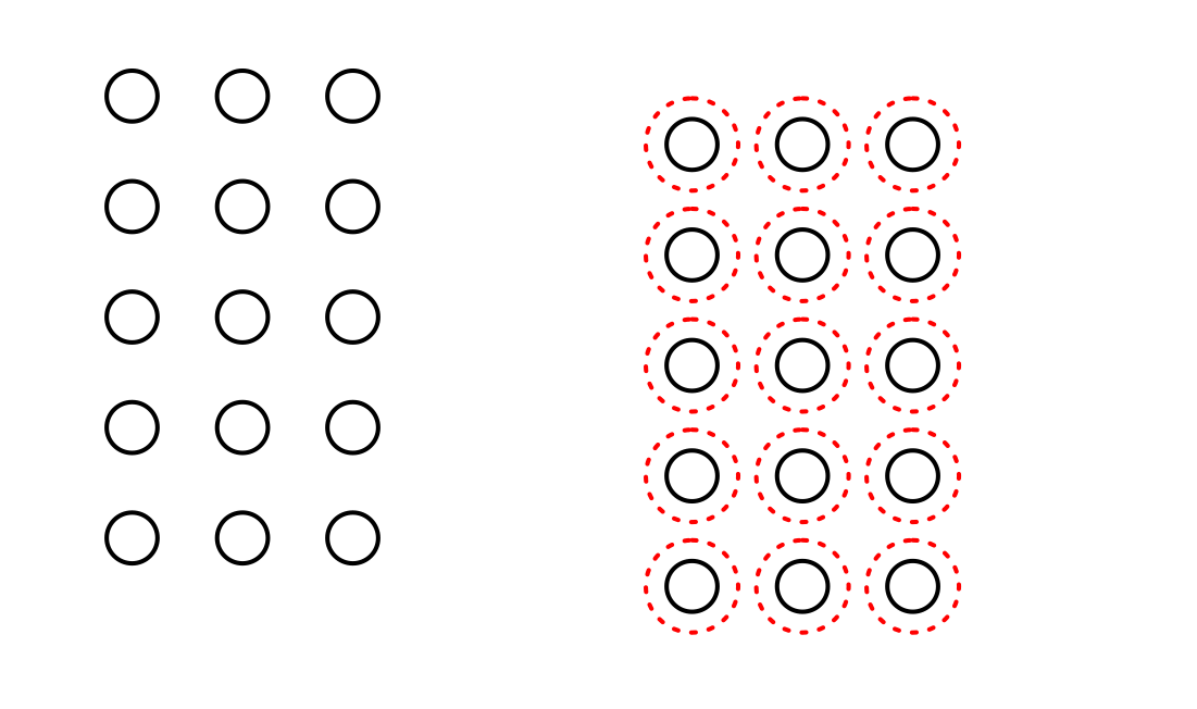
Now, we are going to select all five of the circle groups and ungroup all of them. Then, we are going to select only the small black circles, and group them together. Then, select the dashed red circles and group them together. Then finally, select the black circle group, and the red circle group and group those together.
becomes this after grouping.
The reason for that is that the grouping feature is layered, and you can have multiple layers of object groupings. Later, we are going to ungroup the two different circle groups, but leave each of the circle groups in tact.
The dotted lines around the two different circle groups shows that they are individually grouped, but not grouped together.
And here they are grouped.
This group is a two layer grouping. The first ungrouping command will separate the two groups of circles from each other. The second ungrouping command will separate each circle from the other, and you will have 10 separate circle objects. This will be useful in the build of our board.
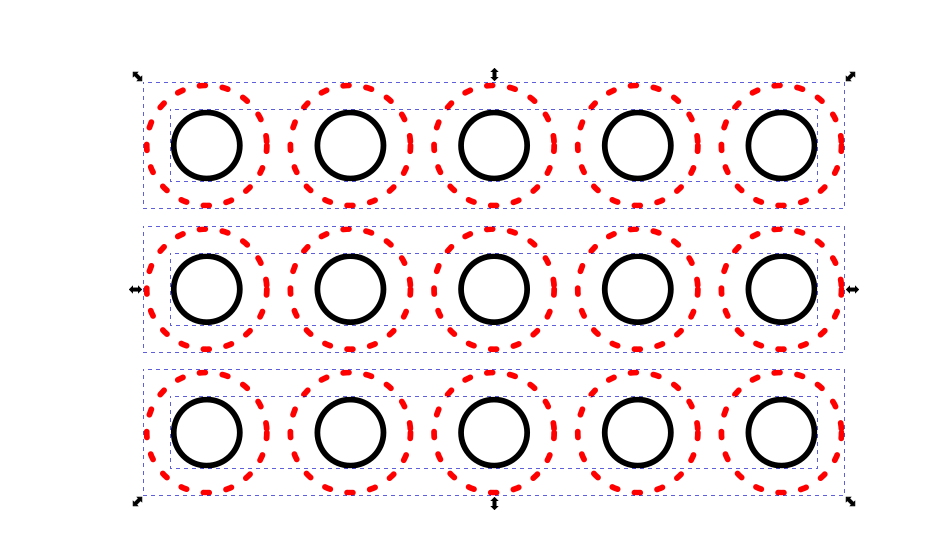
Now, copy / paste two more groups so we can build our first three player group of 5 holes. Then select them all and center them on each other like before. This time, to space them out, we are going to add the “+.25” and “+.5” to the “Y” dimension box.

Once you get there, select all three of them, and perform one ungrouping command, to separate the groups of circles.
Re-select just the small black circle groups, and group them together. Re-select just the red circle groups, and group them together.
Then select those two groups, and group them. Now you have a three level grouping. Personally, I think that the spacing is too close between the rows of holes, but for this, it will be fine. Normally though, I would add at least 25-30% additional spacing between player runs compared to hole-to-hole spacing within one run.
Let’s turn this group 90deg, so we can add numbers. Select the group, and click the “Rotate left 90 deg” icon.
And you get this:
Your first 3 player 5 hole array
4 Likes
Thanks for the instructable @MadHatter !
You’re welcome. There’s more coming, but I am going to be out of town this weekend, so the next part won’t be until Monday.
Okay, now that we have our first array, let’s copy it. I always keep copies of every different element of my boards so I don’t ever have to re-create anything. Copy it, ungroup it [CTRL]+[SHIFT]+G, and delete the red outer lines.
Then , let’s measure the vertical length of the holes, because I would like to add lines between the two rows of holes, just because. I think the break in the lines between groups of holes aids in identifying the 5 count if I end up making the groups too close. We’ll see what that looks like later.
To select individual objects in a group without ungrouping, you press and hold [CTRL] and select the first object with the [Left Mouse Button]. To select the second object, you continue to hold [CTRL] and also press and hold [SHIFT] and then select the second object with [Left Mouse Button]. Now that you know how to do it, select the top left circle, then the bottom left circle in the new group that does not have the red circles.

The total height of the two circles is 1.125" We are going to make a vertical line, then make it 1.125" tall.
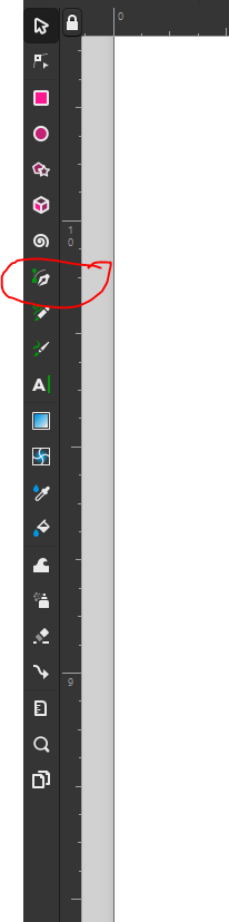
This tool allows us to draw straight lines. In Inkscape, when you make the first mouse click, that is the beginning of the line segment you are making. Each successive mouse click adds a node, and continues drawing the line. To stop drawing the line, you need to doubleclick. If you hold [CTRL] after starting your line, it will limit the angle of the line segment to 15 degree increments, so it is easy to make horizontal or vertical lines this way. To make a short line segment:
Select icon.
Click on the canvas.
Pres and hold [CTRL]
Draw a vertical line, either up or down.
Double-click to end the line.
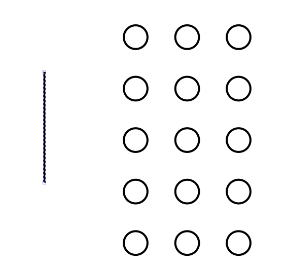
Select the arrow icon in the top left corner of the left toolbar. Now, you can edit the height in the “H” dimension box to be 1.125". Once that is done, move the line to between two rows of circles. Then do a copy/paste, and move the second line between the other rows. Their location is not too important right now, as long as they are approximately located.
Now, we want to select the top three circles, so we do the [CTRL]+[Left Mouse Button] for the first circle, then [CTRL]+[SHIFT]+[Left Mouse Button] for the other two holes, as well as the two lines. The order of selecting the 5 objects doesn’t matter - except for the first object. The first object must be a corner circle.
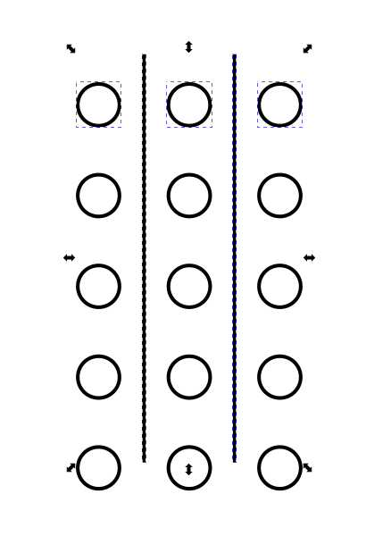
Now, we go to our align toolbar, and select “Align Top Edges”
Then select “Distribute Horizontally With Even Distance Between Centers”
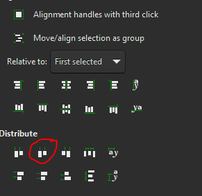
And you get two lines that are indexed at the top (but should be centered, since they are the same length as the array), and evenly spaced between the holes.
Let’s group that new assembly, and make a copy.
Final step of assembling the array before we start making our board is adding numbers. One really neat thing about Inkscape is you can change the line width, as well as the ends of the line. What this allows me to do is to see what the lettering would look like if cut with an end mill.
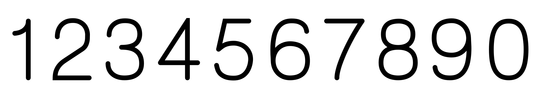
Example: I have the CamBam Stick fonts. I want to cut numbers with an 0.0236" end mill, so I make my text, which for this will be “This is my test text 1234567890”.
Regular text is a closed vector, with the vector line set to “no show” and the fill of the closed vector filled. The are not made for cutting along the vector path that defines their shape. The CamBam stick fonts are designed specifically for the cutter to follow their vector. Many of the CamBam stick fonts do not have closed vectors (8, 0, B, D, . . . do have closed vectors due to their shape), so, when we create test with something like Arial or Colibri, we get this:

But when we change it to CamBam Stick 3, it becomes:

We have to go into our Fill and Stroke settings to make the vectors visible, and the fill invisible, completely opposite to the regular typefaces. Setting the stroke width to 0.010", the text now looks like this:

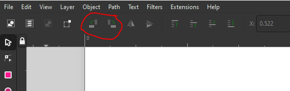
If we zoom in to the numbers (since that is what we are going to be using for this board), we can see that there are lots of square corners, and sharp pointy areas that an end mill path would never be able to replicate, so in the Stroke Style toolbar, we want to select the two middle icons to round the corners and ends of the vectors.
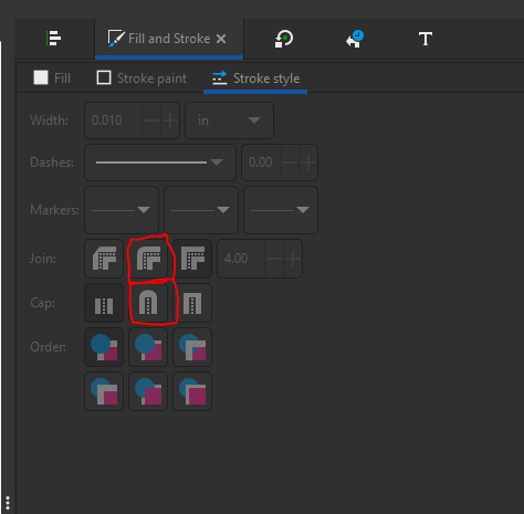
When we do that, we get something more like what it should look like when cut with an end mill.
Now, if you want to see what the font would look like with a different end mill size, all you have to do is change the stroke width. Go ahead and create a new text box, and hide the fill and make the stroke solid red. If you have the CamBam Stick font, even better.
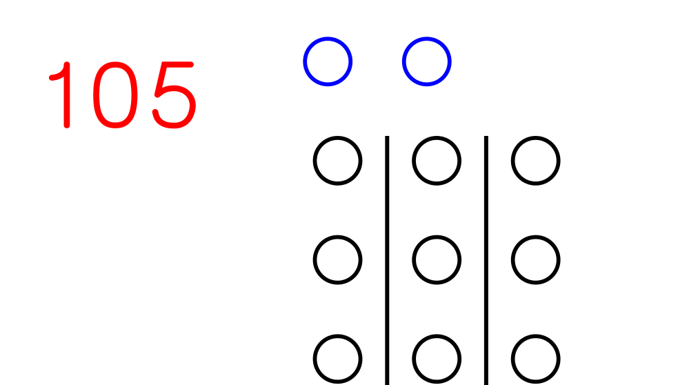
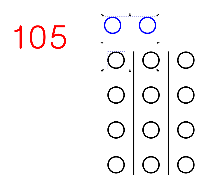
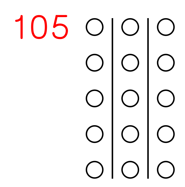
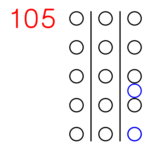
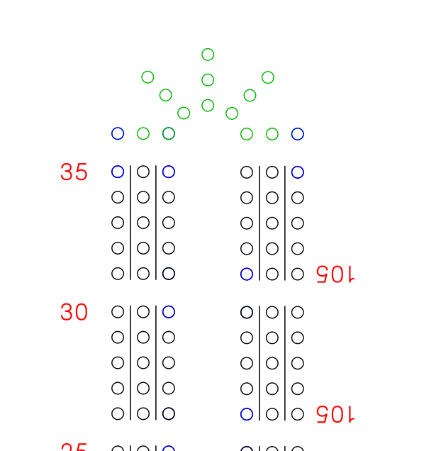
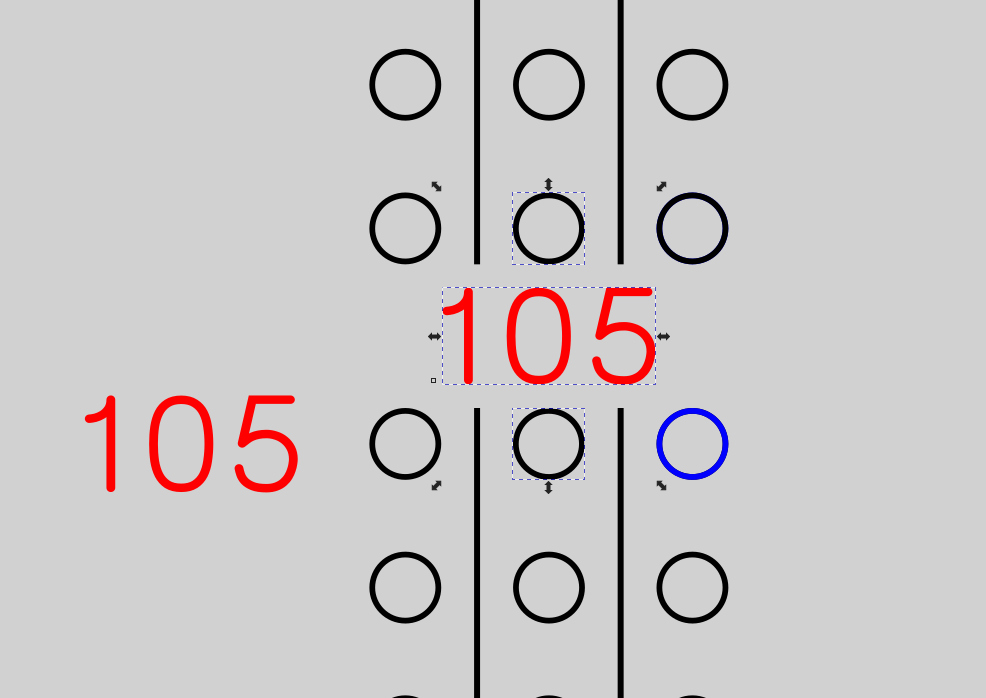
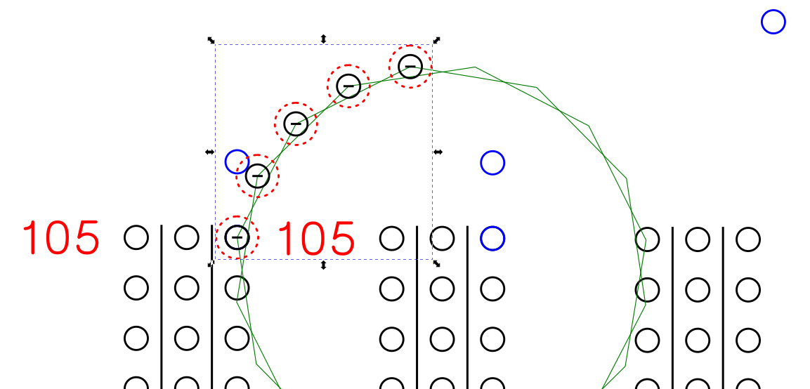
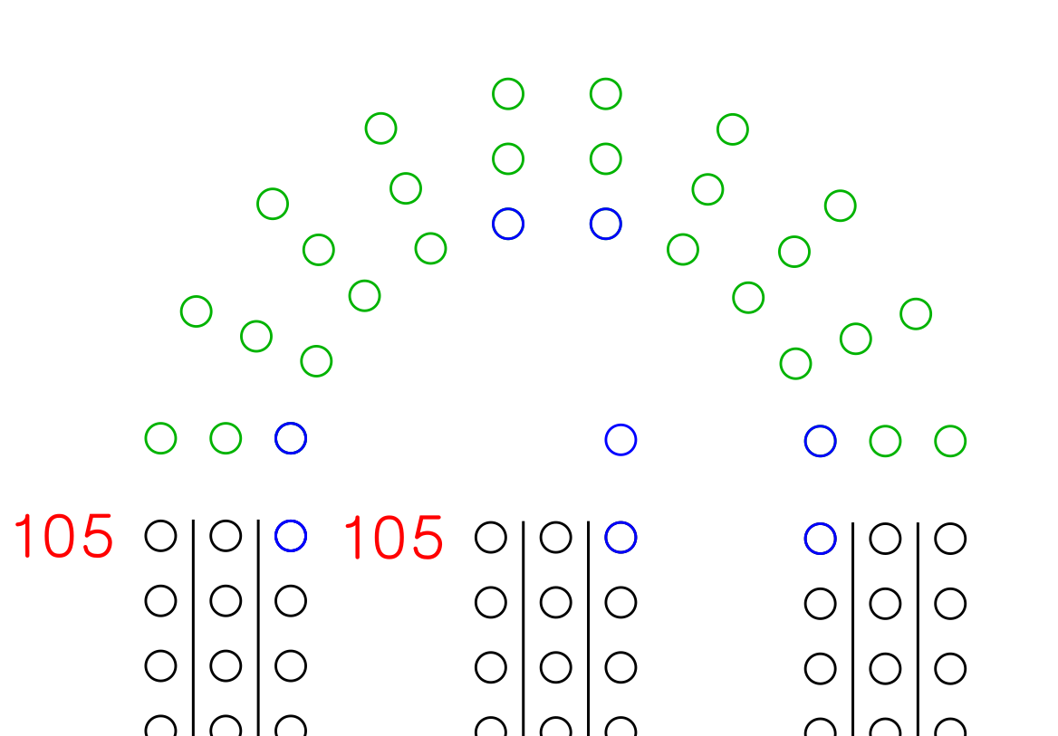
We are going to create a text box with “105”, because that is about the widest number we will be making (105 and 120 are the same width in the CamBam Stick 3 font).
We are going to align the font horizontally centered on the top line of circles, and the spacing is goig to be the same as the horizontal hole spacing. To do this, we are going to copy two of the holes, group them, change their color and use them as the indexing guide for the numbers.
Select the top left circle using the [CTRL]+[Left Mouse Button] for the first circle, then [CTRL]+[SHIFT]+[Left Mouse Button] for the other circle, just to the right of that one. Copy / paste them and then group them. Since I made the font red, make the new circle group blue.
Now, to index the blue group, select the top left black circle using [CTRL]+[Left Mouse Button], then select the blue circle group by releasing the [CTRL] and pressing and holding the [SHIFT] and clicking on the blue circle group with the left mouse button.
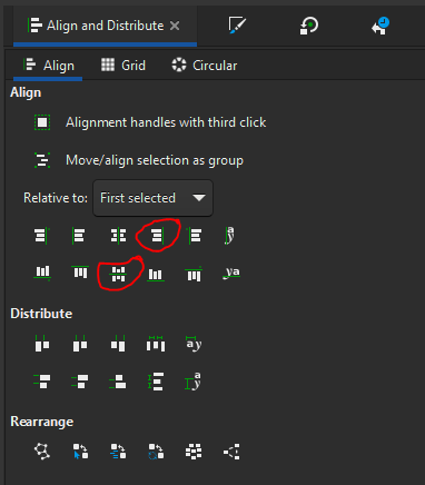
Using the alignment toolbar, you can right align, and top align the blue circles to the black circle.
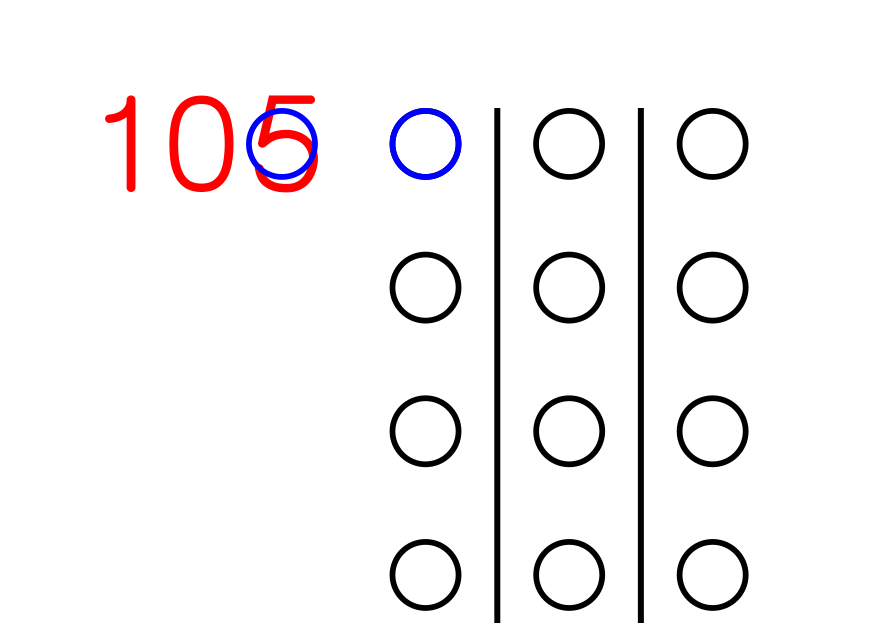
Now, to align the numbers to the left-most blue circle, [CTRL]+[Left Mouse Click] the leftmost blue circle, then elease the [CTRL] and press and hold the [SHIFT] and click on the “105” text box.
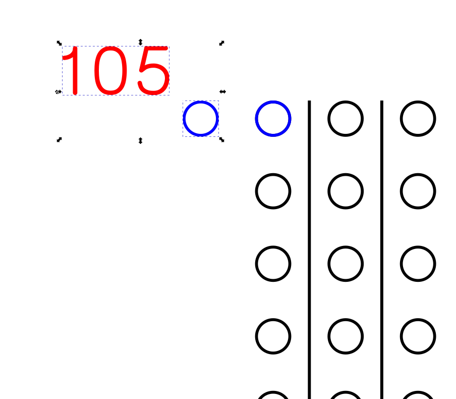
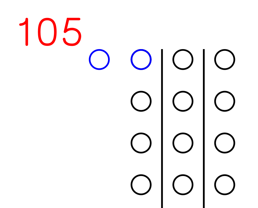
Now, use the alignment toolbar to right align them, and center on horizontal axis.
And you have:
Move the blue circle group out of the way (we are going touse it a bit later) and you get a nice number group spaced nicely next to your circles.
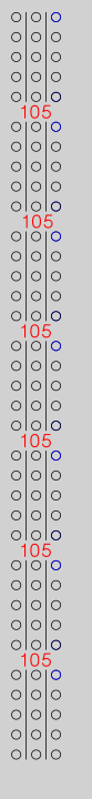
Group these together, and you have a 3 x 5 array, with lines and numbers.
4 Likes
This is going to be a short one because I want to go to bed soon. ![]()
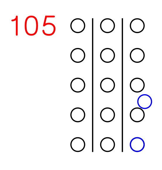
We are gonig to set the spacing between the circle arrays to150% of the hole spacing between the circles in the array. Make a copy of the two blue circles group, and ungroup them. Then select one of the bottom circles in the array, then select one of the blue circles.
Use the “Center on vertical axis” and “Center on horizontal axis” buttons to colocate the two circles.
Then, move the other blue circle to the space between the black circles above the aligned blue one:
Now, select the two black ones, and the blue one (at least one of the black ones first, since we base our alignment on the first selected) just above and below it.
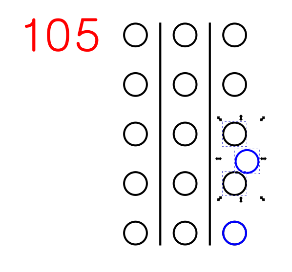
Now, use the “Center on vertical axis” button, and the “Distribute vertically with even spacing between centers” button. Select the two blue circles and group them. You should end up with this:
Let’s take that group up to the top of the array, and align it with the top right circle. I selected the top right circle, then the blue circle group and used the “Align right edges” and then “Align bottom edges”. Since they are circles, it shouldn’t matter which sides you align.

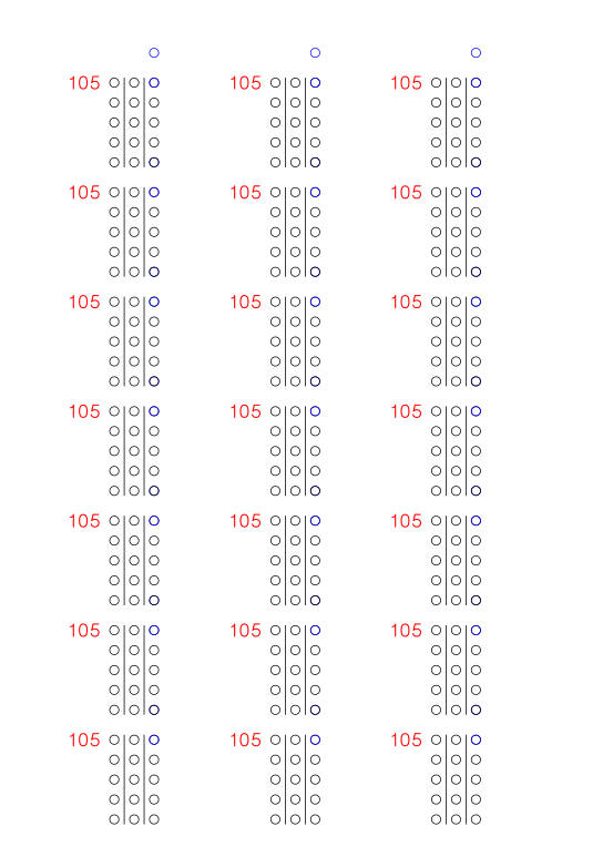
Now group that, and you have your stackable arrays with 150% spacing between them. Let’s see how that looks. I did a copy / paste and lined up the bottom right circle of the upper array with the blue circle sticking up from the top right corner of the bottom array. The snap feature should gram the array you are moving, and snap the circles together, indexing it for you. I made a group of three arrays, then coiped that, and indexed that array with the first three. I ended up adding one more to get 7 arrays in a line. I did a copy / paste of that line and created two more and just kind of spaced them out for now. This took about 45 seconds to do due to the automatic snap feature.
Tomorrow, I’ll show you how I make the curved paths to join the vertical rows.
7 Likes
this is really well put together @MadHatter
Okay, if you’ve played cribbage, you have played on a board that had the inside track holes so close they almost touch. If you have any kind of tapered peg, and end up with them right next to each other, they end up sitting at an angle and pressing up against each other. I understand the desire to have holes not spaced miles apart, but I feel that there is not enough consideration for hole spacing based on the largest diameter of the crib pegs. My personal preference is to keep the same spacing for the inside track as the regular hole to hole spacing.
So, to make a 5 hole U-turn, we start with a line segment that is the same length as the distance from hole center to hole center. There are a couple of ways to do it.
- Use the snap feature to draw a line from the center of one circle to the center of the next.
- Since the numbers are easy, we can look at the circle size by selecting a single circle (0.125") and then selecting a second circle. The new dimension in the box is the total height (0.375"), so you subtract the single circle dimension from the total dimension and get 0.375" - 0.125" = 0.250" hole spacing.
- Remember that you set the hole spacing at 0.250" when you started.

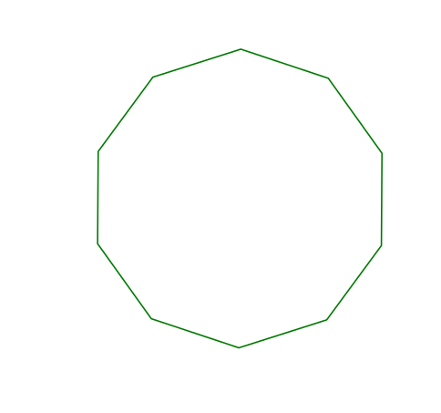
Okay, so however you got it, you now have a line that is 0.250" long that we will use to calculate the size of the regular decagon. Because I have done it “the hard way” before, and I found a new and much easier way to do it, I am going to teach you the new way.
Google “side length decagon calculator” and find a site that calculates the outer circle radius based on the length of a side of the decagon. I used this one, but you can use whichever you want: Decagon online calculator and formela
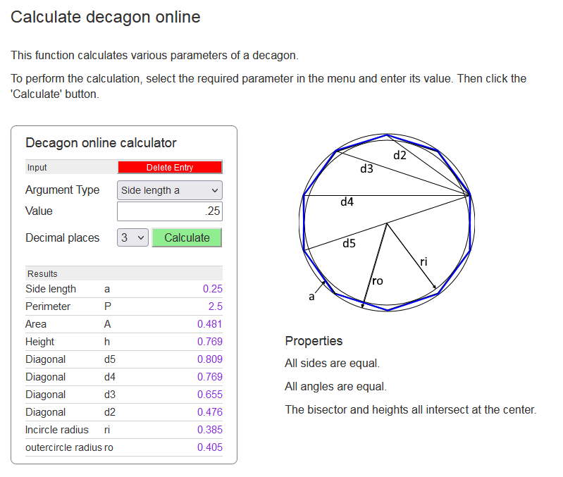
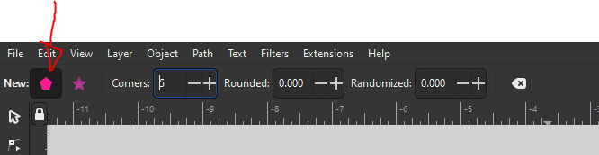
I put in the side length a of 0.25, and get the radius of the circle that the decagon points touch. Now that we know the radius, we are going to make our own decagon in Inkscape. Select the polygon icon:
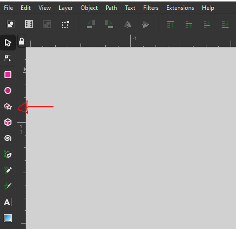
That pops up a toolbar that allows you to decide if you want a regular polygon (you do), change the number of sides (you do, to 10), as well as whether you want rounded corners (you don’t), and randomly place the vertices (also, no).
So create a decagon, and orient it so that two sides are either perfectly vertical, or perfectly horizontal (or as near as you can get them). You can rotate the object by clicking it once to select it, and then clicking it again to toggle object rotation. Also, I just found out accidentally - the little crosshairs in the middle of the object - that is the rotation point. you can move that around, and when you rotate, it will rotate about those crosshairs.
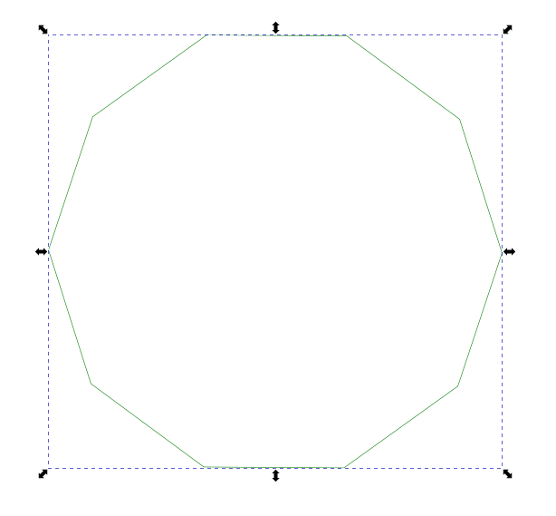
Now that I have my decagon, and I have two sides horizontal, I use the width dimension (since that is the greater dimension, and these points would be on the outer circle, which we know the radius of).
I make sure the ratio lock is on, so the decagon is scaled proportionally, and enter into the width dimension box “.405*2” (without quotation marks) because we need the diameter of the circle, not the radius.
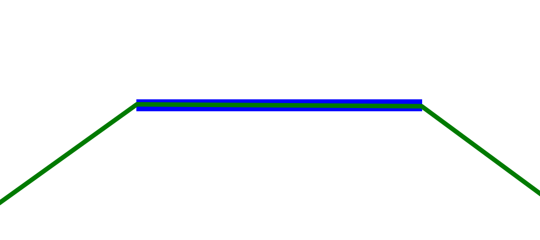
Now, if you take your 0.250" line (blue) and bring it up to the decagon (green), it will snap to a vertex and you can see that the sides of the decagon are indeed 0.250" or close enough for us.
So, if you have your decagon with the “pointy ends” at the top and bottom, you can skip the next step. If you have the “pointy ends” on the left and right, like I do, you need to rotate your decagon 90deg, either by using the rotate function, or just selecting it and clicking the rotate 90deg buttons. It doesn’t matter which one you click.
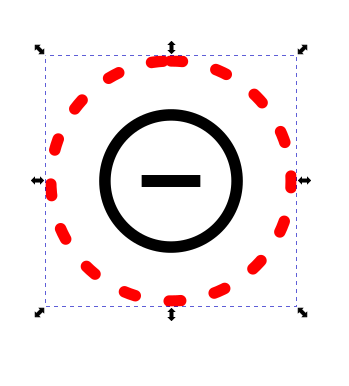
Now, I grab one of the black circles with a red circle around it, so I can see how close the peg heads will get. Remember how I said I don’t get rid of anything? Here’s my “scrap pile” off to the side of the canvas.

I grab the single group of circles, and make a copy. I am going to use the snap feature to snap the circles to the vertices of the decagon, but I have found that the snap feature is unreliable when trying to snap the center of a circle, so we are going to put a short line in the middle and group it with the circles so we can snap to the midpoint of the line with the vertices.
Use the center vertically and horizontally buttons in the alignment toolbar , then group them.
Move it to the first vertex and hover the center of the circle over the vertex, and it should try to snap to the midpoint of the line. We are only using the top center vertex, and the two to the left and right of it.
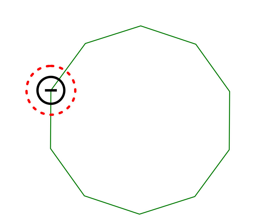
It should go:
Copy
Paste
Move
Snap
[Repeat]
And take about 30 seconds to do the other four.
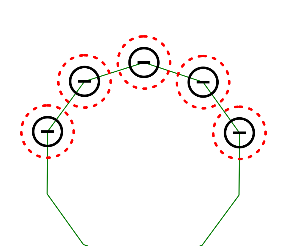
Now, you can move the decagon out of the way, Make a copy of the circle group, and put it in your “scrap pile”. Select all of the circle groups, and do 1 ungroup, and then delete the center lines.
Now, from your scrap pile, grab three holes across by doing a [CTRL]+[Left Mouse Button] to select the first circle, then select the other two by continuing to hold the [CTRL] and also pressing and holding [SHIFT] and selecting the other two with [Left Mouse Button].

Copy this group, move back to your canvas, paste them and group them.
Now, we are going to change the color of these because we are going to use this group to actually create the three rows of holes that go around the curve. Let’s make them green, since there is nothing green in the grouping yet.
Select the three circle group, copy it, and paste four more copies. We need two groups that are horizontal, one that is vertical, and two that are at angles - one 45deg and the other 135deg. We can do this with the rotate function, and setting the rotation angle to 45deg.
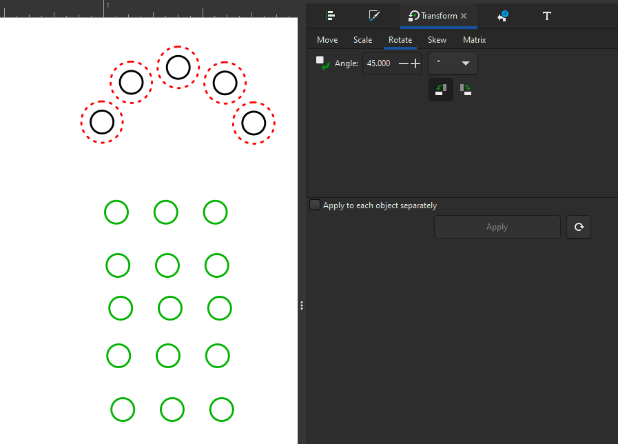
The great thing about these little groups is they are symmetrical, so you can rotate them whichever way you want and it works. You’ll want to select one group, and rotate it 45 by clicking “Apply” once. Select another and click “Apply” twice. Pick a third and click “Apply” three times. That’s it. All of the groups are set to their correct angles. They look like a mangled mess, but we don’t care because the snap feature makes it easy to place them.
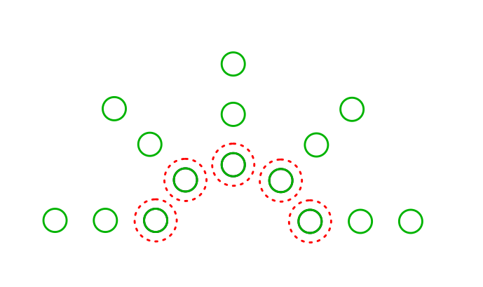
Now, we just place them with the snap feature.
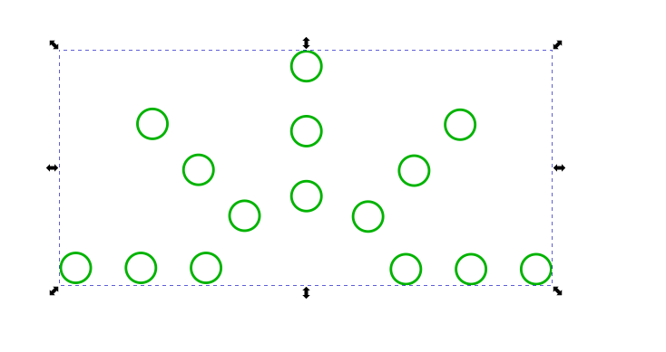
Grab the red/black circle group and move it to the scrap pile, and group all of the green circle groups. Make a copy and throw it in your scrap pile. Yes, your scrap pile will be pretty big by the time you are done, but you will have every sub-assembly needed to remake your design, or to launch a new design with some of the sub-assemblies.
Go get your blue circle group that is the 150% hole spacing jig, and snap that to the two bottom holes, so we can index this group to the other arrays we have.
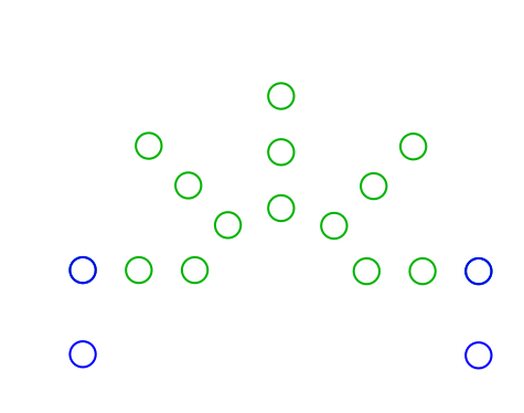
Let’s put it together with the other arrays.
It looks like it lines up nicely, but I see an issue now. the font is too big for the spacing. I typically do not do the back-and-forth boards this size, so it was not something I considered. An option is to put the numbering in the middle of the holes at the spacing between arrays. I am not a fan, but everyone has their opinion, and if you like it, do it. This is a quick and dirty mock-up to see how it looks. I did the [CTRL]+[Left Mouse Button] to select just the number text box, and copied it. I moved it between the two groups, then did the selection of the two circles first, then the text box, and did an “Align vertically” then a “Distribute vertically with even spacing between centers”.
It’s not terrible. . .
So, we made a small 5 hole arc. Tomorrow, we will make the 10 hole arc.
5 Likes
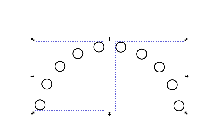
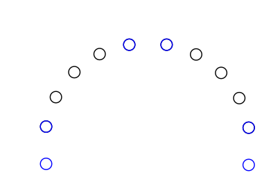
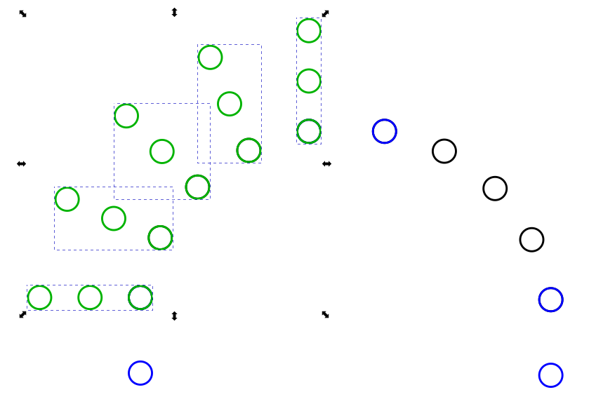
Okay, now to make our 10 hole 180deg arc. Remember this dude?
We’re going to make a copy of it, and then scale it to 200% by making sure the ratio lock is on, and then typing in “*2” (without the quotes) in either one of the dimension boxes. Then we’re going to copy / paste so we have two of them.
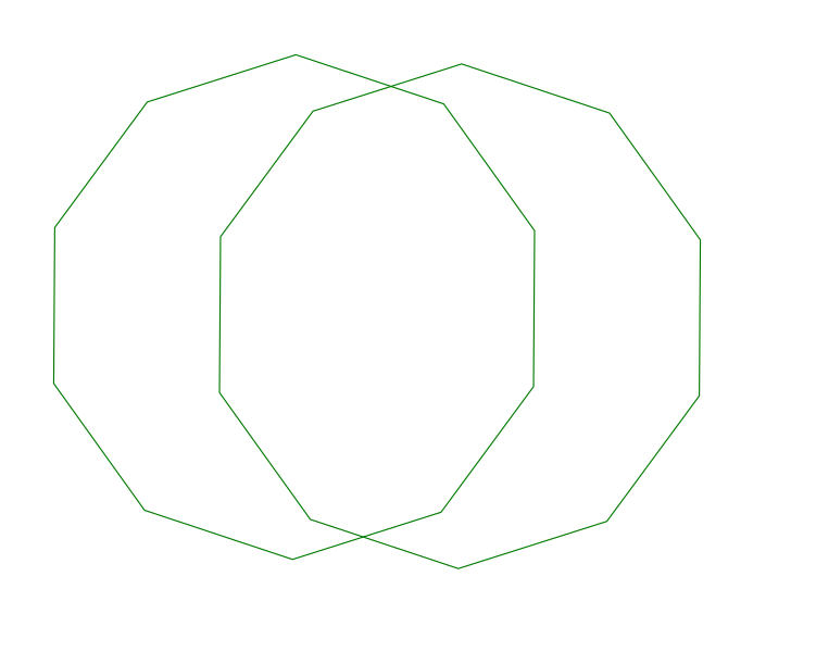
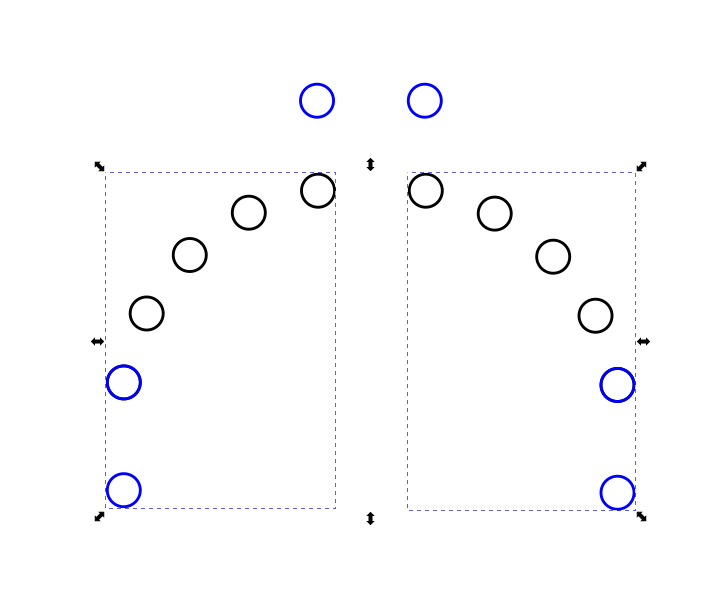
Now, a decagon is made of 10 - 36deg angles. We want to rotate one of them half that distance, so use the rotation function, and rotate it 18deg. Now, canter align them both vertically and horizontally, then group them together. You should have this now.
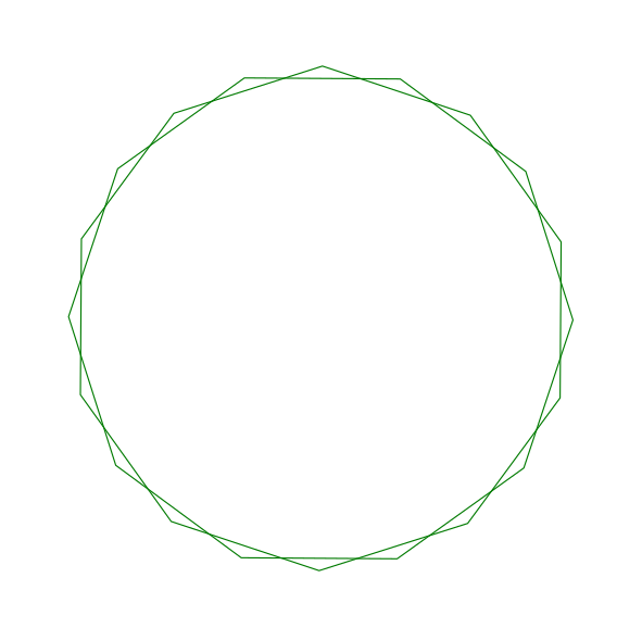
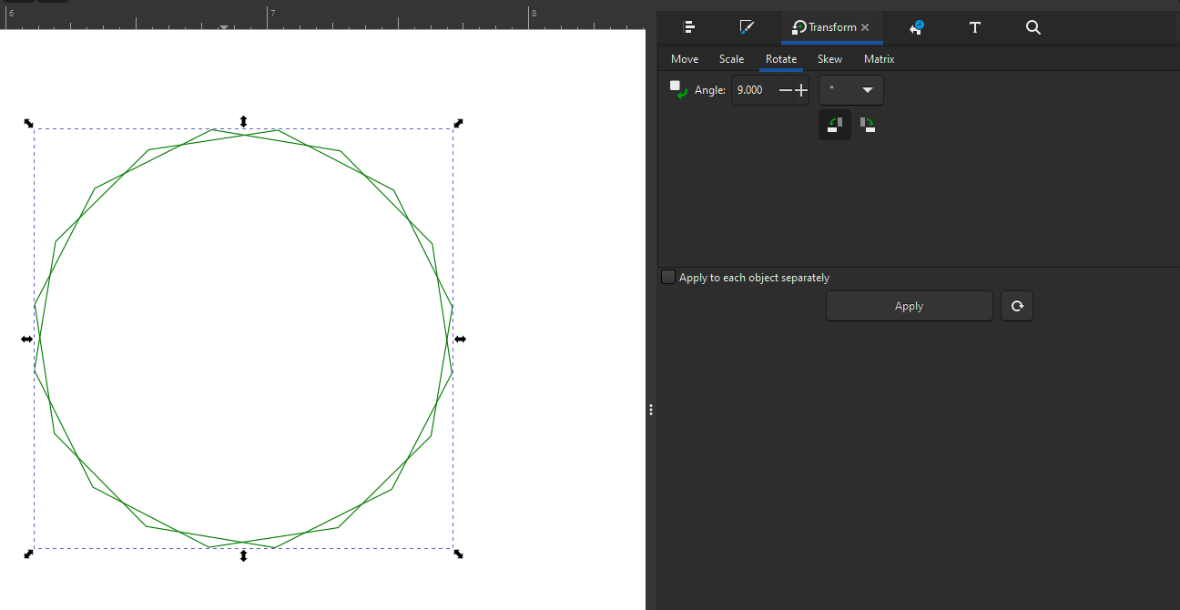
Because we are going to end up with two groups of 5 holes, we can’t have the vertex at top dead center, so we need to rotate this group half the angle between the vertices. Right now, there is a vertex every 18deg, so we need to rotate this group 9deg. So, do that so we can start snapping circles.
As you can see, there are two vertices at the top of the bounding box now, which is what we want. Now, go grab your group that has a red dashed circle, black circle, and short black line.
I started at the top two vertices and just did a paste, paste, paste as I worked around the decagon group, dropping the circles near, but not on the vertices they will be snapped to.
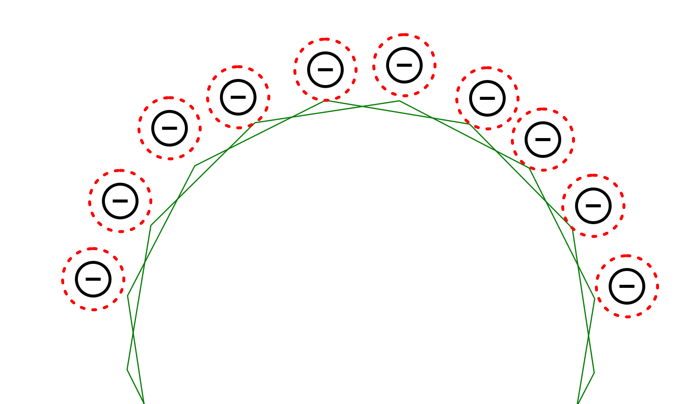
Then I zoom in and grab one of the circle groups by the center line and snap it to one of the vertices, then move on to the next one. If you grab the object near where you want it to snap, Inkscape applies a “weight” to where your pointer is for snapping. The closer you are to the node you want to snap, the easier it is to get it to snap there.
So, now that you have all of your circles snapped to the vertices, you can group them into two groups of 5 circles.

Make a copy and put one copy in the scrap pile. Move your grouped decagons over there as well. Then ungroup them both (you will have to perform the ungroup command twice to be able to delete the individual objects, because the grouping is two levels right now), and delete the red circles and little lines in the middle, and re-group just the black circles.
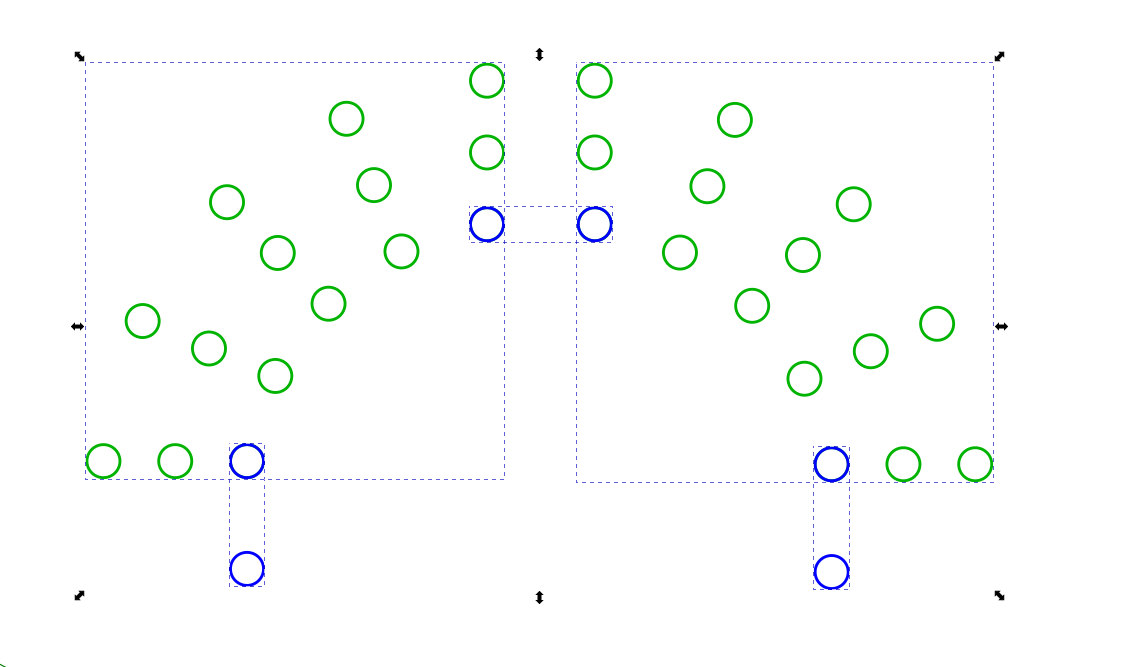
Now, we go grab the blue 150% spacing circles and copy them and bring them over. We are goin to want 3 copies - one for each of the arcs, and one for between the arcs.
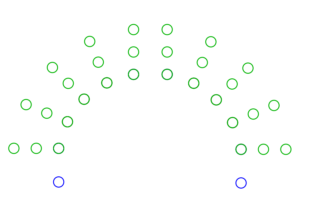
Put all together, we have this:

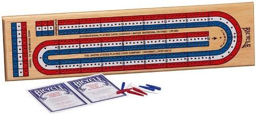
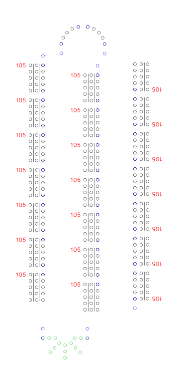
Now, we can go put that on our groups of arrays and we should be able to make an entire run of 120 holes. Let’s see how that goes. I realized that if we go back and look at the board we are trying to duplicate, the large 10 hole arc is at the top of the board, and the 5 hole arc is at the bottom, so let’s get our three rows of holes, and start at the top with our 10 hole arc.
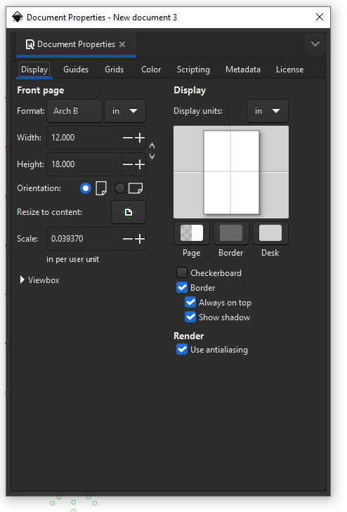
I was feeling kind of constrained to stay on the canvas which I had set to 8.5" x 11", so I changed the document to 12" x 18" to give me more room on the canvas to work. It really doesn’t change anything for what we are doing, other than having a larger bright white area to work instead of working in the gray area. You can change yours as well by going to [File] - [Document Properties] and either selecting a defined size from the dropdown, or entering your own dimensions directly. Here is where you can also set the dimension units.
Anywhooo, back to finally putting it all together. I already know that our number location is going to be a problem, but we are going to lay out the holes anyway, just to get a feel for how it goes together.
I have three rows of circle arrays, and I flipped one row up side down, so the pegs are always “looking at the numbers upright as they travel”.
Zooming in to the top arc (we’re not going to worry about the other two holes for now) and align the inside track of holes.

Everything snapped nicely, and it took about 15 seconds to put those together. Let’s go down to the bottom and align the bottom arc and last row of circle arrays.
Well, the numbers are definitely going to have to move, but the other thing that I feel is an issue is the uneven spacing between the rows of circles. Let’s see if we can even that out. I think we can make our 10 hole arc a little bit bigger, and get that spacing even. I think that is preferable to making the 5 hole arc smaller and crowding the pegs. Let’s see what we’re going to do.
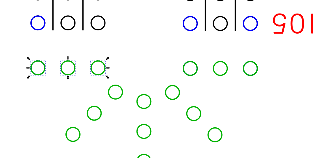
Let’s grab two individual holes from the wider gap using the [CTRL]+[SHIFT]+[Left Mouse Button] and then do a copy / paste / group.
I went to the top, since that is where we will be working.

After the copy / paste / group, I changed the to red, since I am not using any red circles right now. I use the different colors because it is easier to see different groups when they are different colors, and I remember what the different groups are for when they are colored.
So, now let’s snap that red group to the left side of the center array, then move the left array so that it indexes with the right-most hole.
It looks cluttered, (because it is), but we know what is going on and what each color is. The blue is our 150% spacing group. The red is the “make the lines of arrays spacing even” group. And the black circles are just the holes that are destined to be peg holes.
So, we need to make the grouped decagon bigger, to smoothly span the new gap we created. What is that gap? I’m glad you asked. Use the [CTRL]+[SHIFT]+[Left Mouse Button] and grab the two circles that we need to have the arc align with.
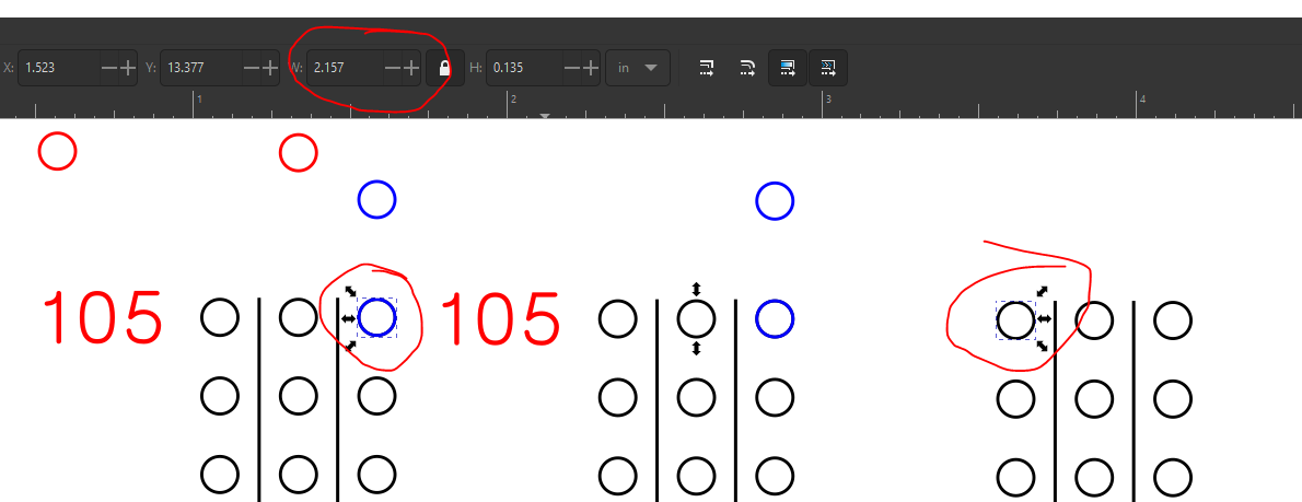
Then we just read the width in the dimension box - 2.157" Now, subtract the width of a circle - 0.125" and you get 2.032" 1.978" Select your decagon group, and enter “2.032” “1.978”(without the quotes) in the dimension box and hit enter.
Preemptive edit - because I have that 150% space in the middle, if you use the stricken value, your holes end up being ~0.054" too wide. Ask me how I know. . . ![]() At least you don’t have to redo anything.
At least you don’t have to redo anything. ![]()
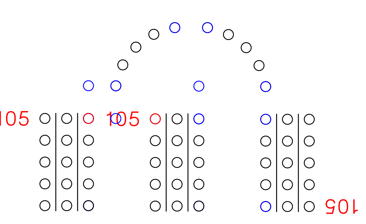
I did a couple of things - I grabbed the left arc from my scrap pile and made a copy of it. then I snapped it to the top right corner circle of the left most line of circle arrays. Then I snapped the decagon group to the center of that line.

Now, I am going to ungroup the left arc circle group and re-snap them to the vertices of our newly resized decagon group, then regroup them.
Now, let’s go copy the right arc circle group, and do the same thing on the other side. Once you are done with that, group / copy / paste copy in scrap pile. Ungroup the two arcs and delete the little straight lines, and dashed red circles and regroup.
Then add in the blue circle group at the bottom and between them.
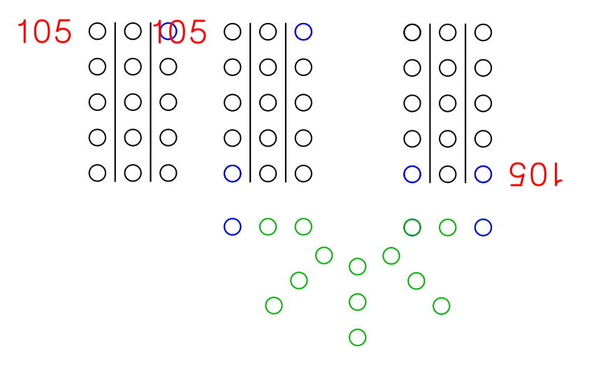
Now, let’s add the rest of the circles in the arcs. Go grab three of the green circles from the lower arc. Preferably three that are horizontal.
Copy / paste / group. Move them up to our 10 circle arc.
I made 5 copies close to where I want them, and now we are going to rotate them in increments of 22.5deg. So set your rotation angle to 22.5deg and rotate one once, one twice, one three times, and the last four times.
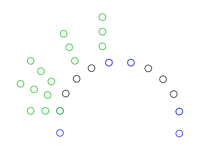
Then snap them to their respective locations. Select the green circle groups only, and group them.
Copy that group, paste it, then rotate the entire group 90deg clockwise, and snap it to the arc.
Now, you can get rid of everything except the green and blue circles. You can check and see what is “under” the green circles by selecting them, and hitting the “move objects to the bottom” button.

After doing that, we have the black circle group, along with the blue circle group. We want to keep the blue circle groups, so do an ungroup, then delete the black circle groups. Select the green and blue circle groups and group them.
Now they are grouped.
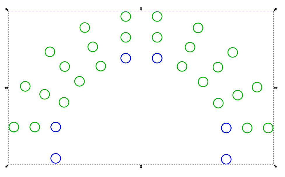
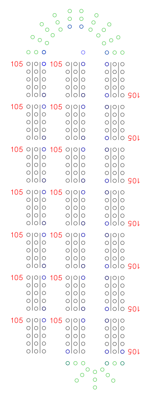
Snap it to the right array group, and then snap the left array group to it.
And finally, zooming out a bit, we see we have something that passes for a cribbage board - almost. We need hole 121 as well as the starting holes. We’ll tackle that this weekend, when we also relocate the numbers, and change them from “105” to what they should really be.
2 Likes
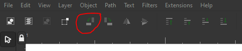
For folks who don’t have access to 3rd party tools, v7 w/ its Linear Array:
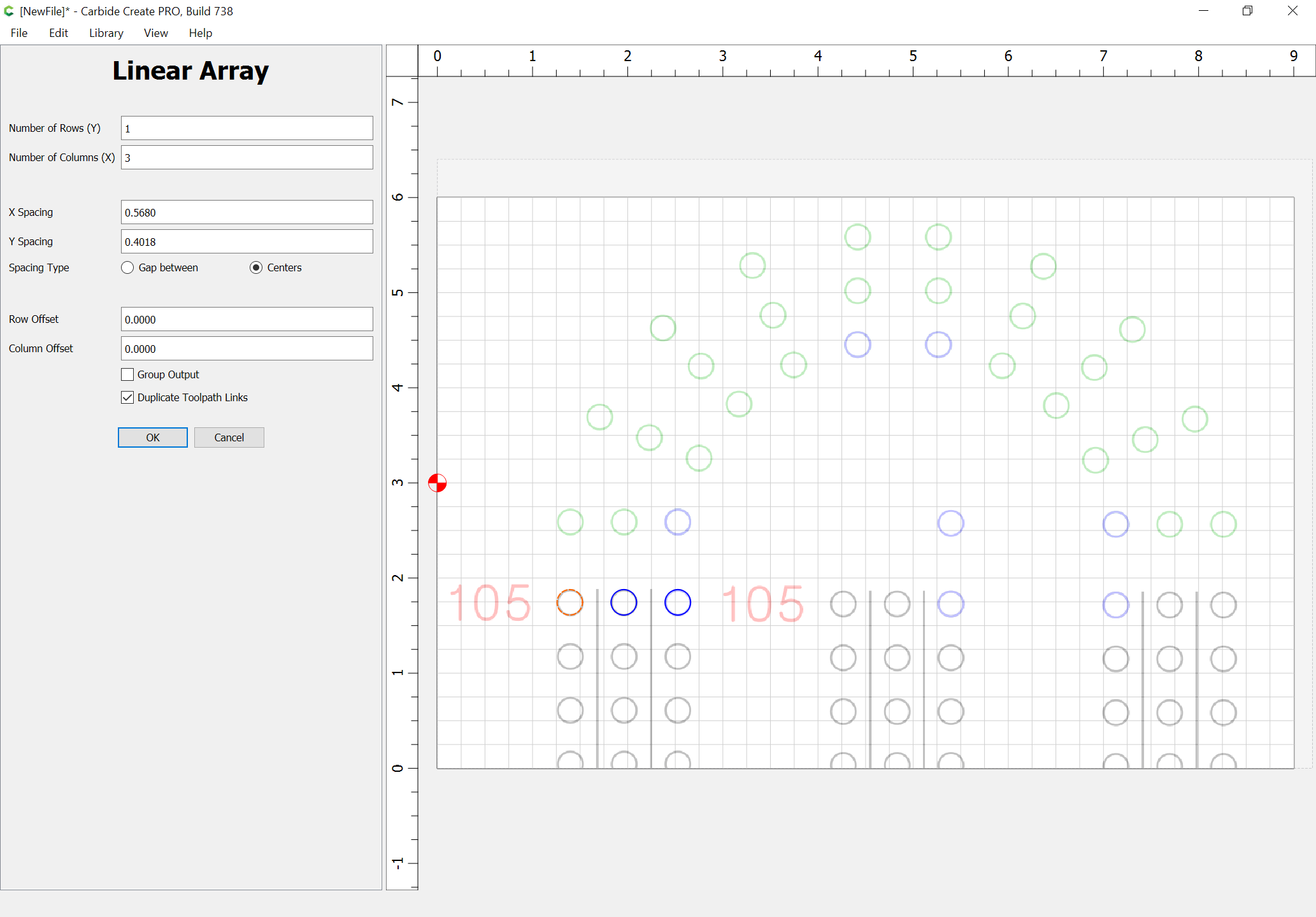
and Circular Array tools:
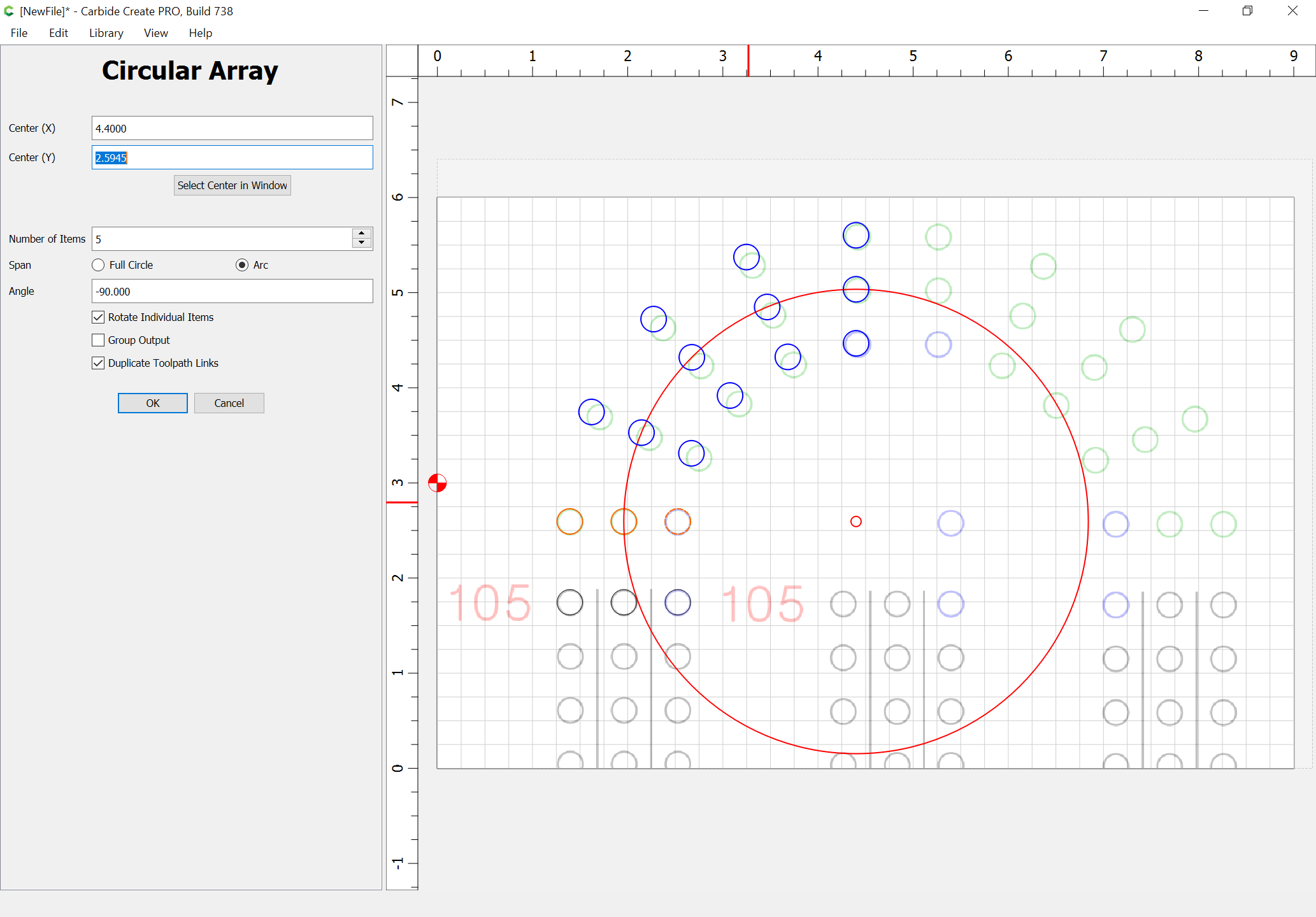
should be workable for this sort of thing w/o the need to draw and rotate dodecagons.
2 Likes
I have actually posted about some of the ones I have made before using Carbide Create. I use the drill tool path with 1/8 inch HSS drill bits. I run the router at the lowest RPM and in most cases have no issue.
I use the linear array to make all my holes in a line and the circle array in Carbide Create to make the paths that have to go around a corner. The link above describes how I went about it for both.
This topic was automatically closed after 30 days. New replies are no longer allowed.