I’m trying to create some curved drawer fronts and I’m really struggling. Hoping someone can help out.
The drawer fronts are, in their final form, to be 50mm tall and 400mm wide. I’m trying to get a smooth curve on the front, a curve I’d want to carry over to the frame parts too.
I can see two ways to do this.
Don’t cut the fronts to size, lay the stock, and frame pieces flat as they would appear on the cabinet so |side|drawer front|side| and then generate the curve over the entire thing.
Cut the fronts to size, mount them upright on my machine bed and cut the curve (an arc) like that.
I’m struggling with any kind of execution with both these ideas.
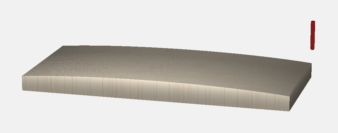
For 1) I’ve created a simple file ( curved-front.c2d (60 KB)
) but it’s not really anything like the gentle arc I’m looking for as is basically a series of steps that I’d need to end up sanding into a curve. It’s not a gentle curve and it’s a PITA to go through each pocket and tweak it.
For 2 I’ve tried to use the circle tool to generate the arc, which is smoother but obviously it wants to be a closed shape, rather than just an arced path. There’s also the issue of mounting the drawer fronts upright securely that I’d need to deal with.
I’m at a loss really, I think the only other method I can think of would be a 3D model of the surface but I’m not really sure how to go about generating that and I’ve not had a great deal of luck with 3D surfacing so far in general.
Anyone come up with some solutions, I’m kind of stuck?
You could do this in the free version of Fusion 360 by simply sketching the cross section (back of drawer on the bottom, bottom of drawer is the sketch plane) then extrude that cross-section to the height of the drawer.
But, that would mean learning Fusion 360, which is a whole thing in and of itself.
Doesn’t matter, as long as you accurately describe what you want.
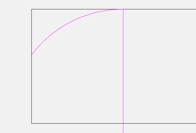
Something like this, an arc that starts tangent to the face 16mm in, and crosses the edge at 8mm deep… That will mathematically describe the shape you want. It can be constructed to those specs.
I’d intend to create rabbets on the flat side to joing to the drawer box - but I haven’t drawn those, I’d expect to do that bit first then shape the face, or what would be the surface.
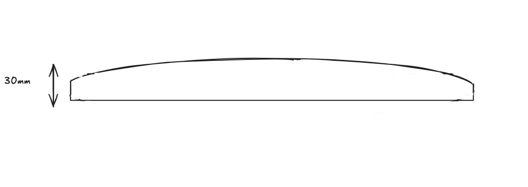
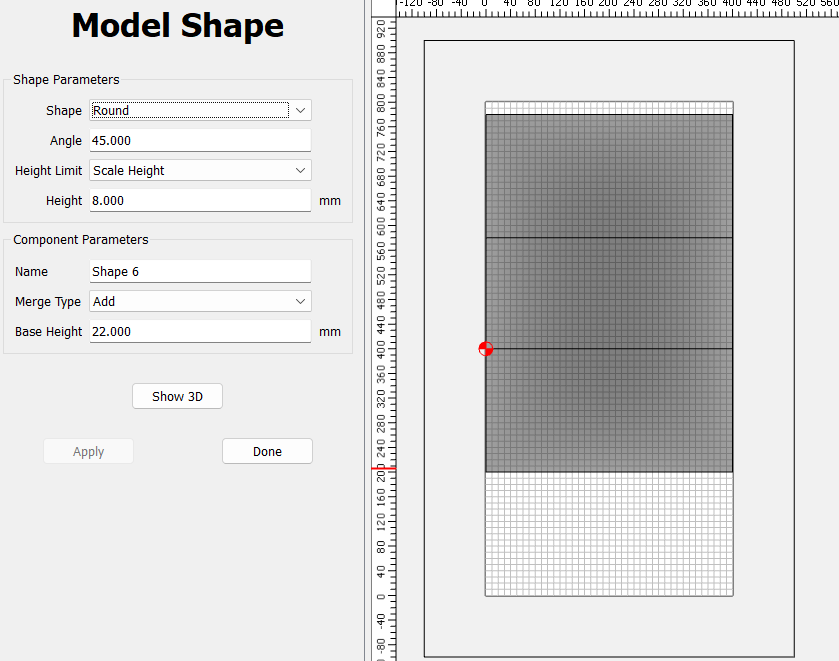
OK, so let’s make some assumptions. It’s 30mm thick stock (your example was 20)
Your curve is 30mm in the center, and you used 8mm depth on the example, so we’ll go with that at the edge.
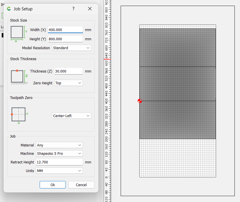
When you model you need to make the stock much larger to allow the shape to develop all around the chosen vector. Since this is 400mm wide, we need to add at least 200mm to the top & bottom to leave a face that’s only curved in one direction.
And if you want the zero point at the lower left corner of the actual stock, we’ll have to cheat. Use the Center-Left zero origin, and make the workpiece 400x800
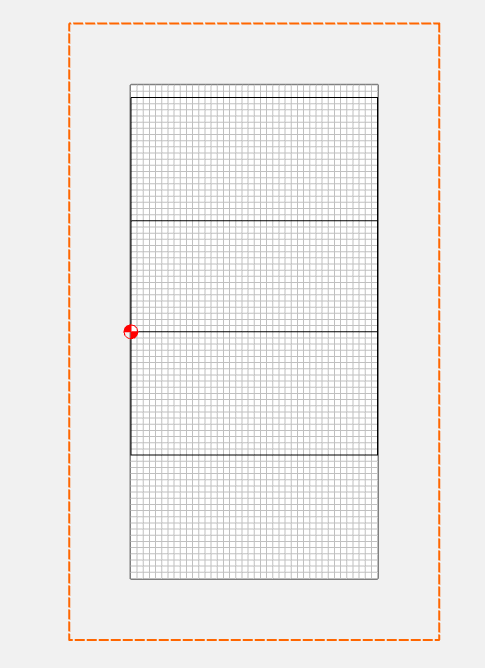
Move your workpiece rectangle so the front left corner is at the zero point.
Make another rectangle that is 400mm taller, so 400 x 580
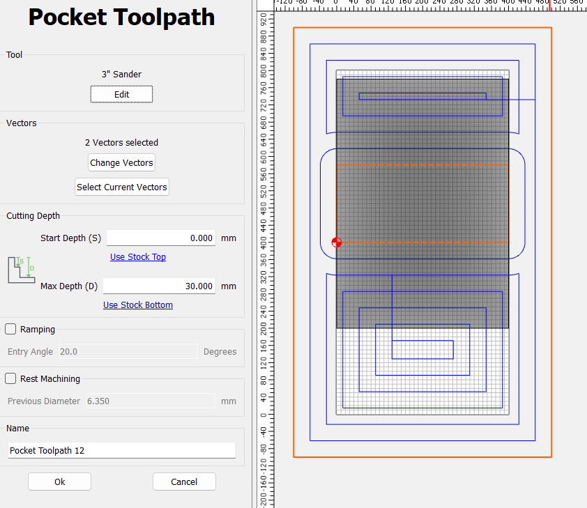
I’ll make another rectangle 600 x 1000 to use as a boundary to remove the excess workpiece just for display purposes. We’ll disable or delete when we post.
Now for the toolpaths, I have a 3" end mill that I use to program my 3" sander, but it will also work for the extra material removal. Select the outside rectangle 600x1000, and the workpiece rectangle 400x180, and do a pocket path with depth of cut 30mm, and max depth 30mm