Folks,
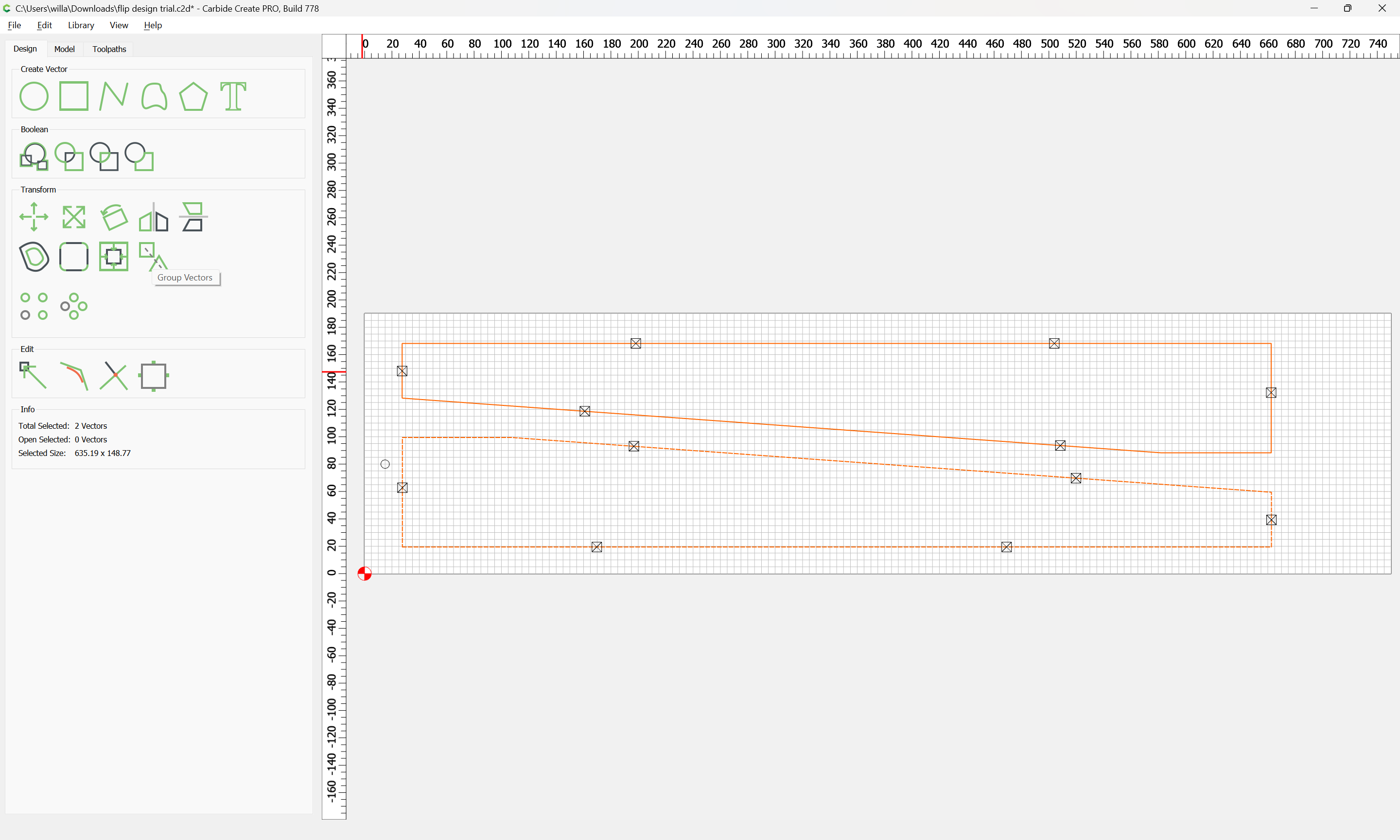
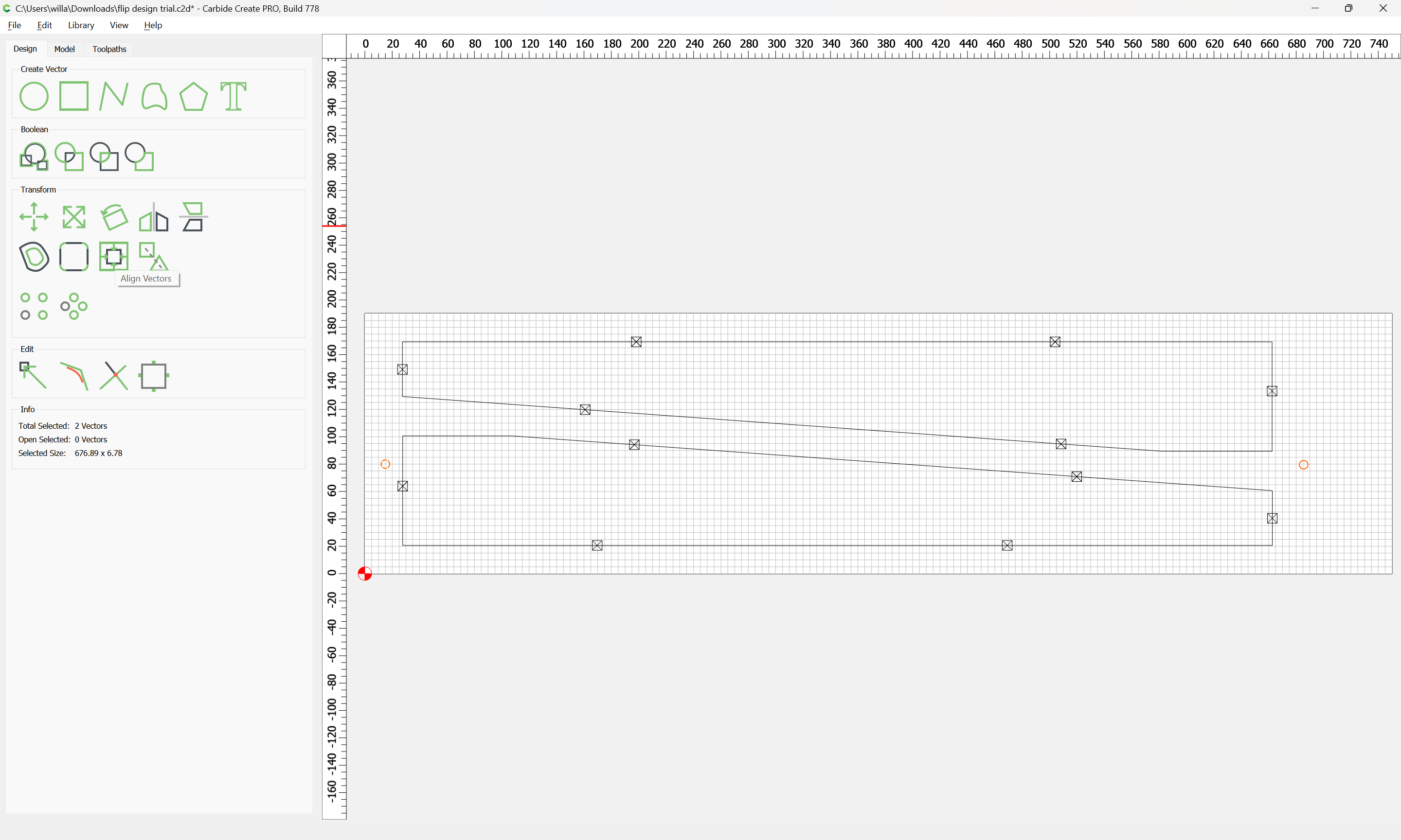
I like to cut a chamfer on a table leg on both sides. The leg is tapered. Other messages I have read says I need to change scale for the axis to flip to -1. I don’t have the option to do for scale on each axis in the design mode ( I am doing 2D).
I think I am missing a simple step. Can someone help? The file is attached.
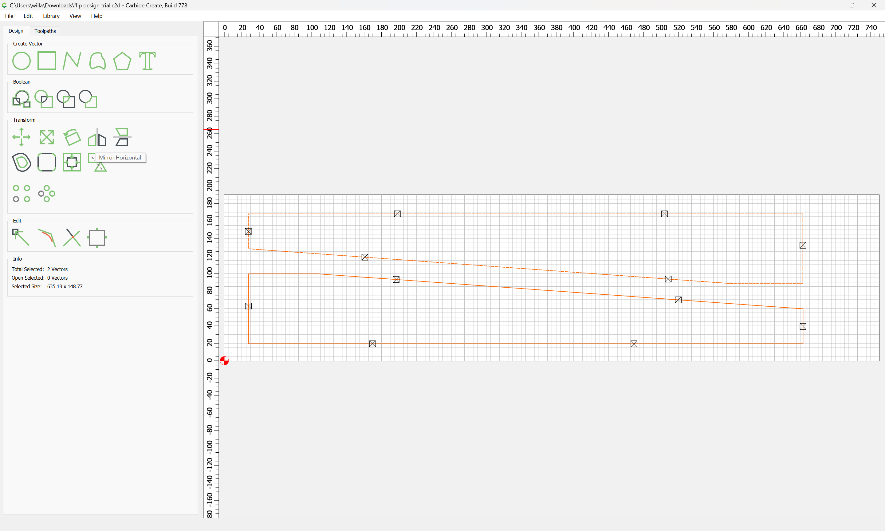
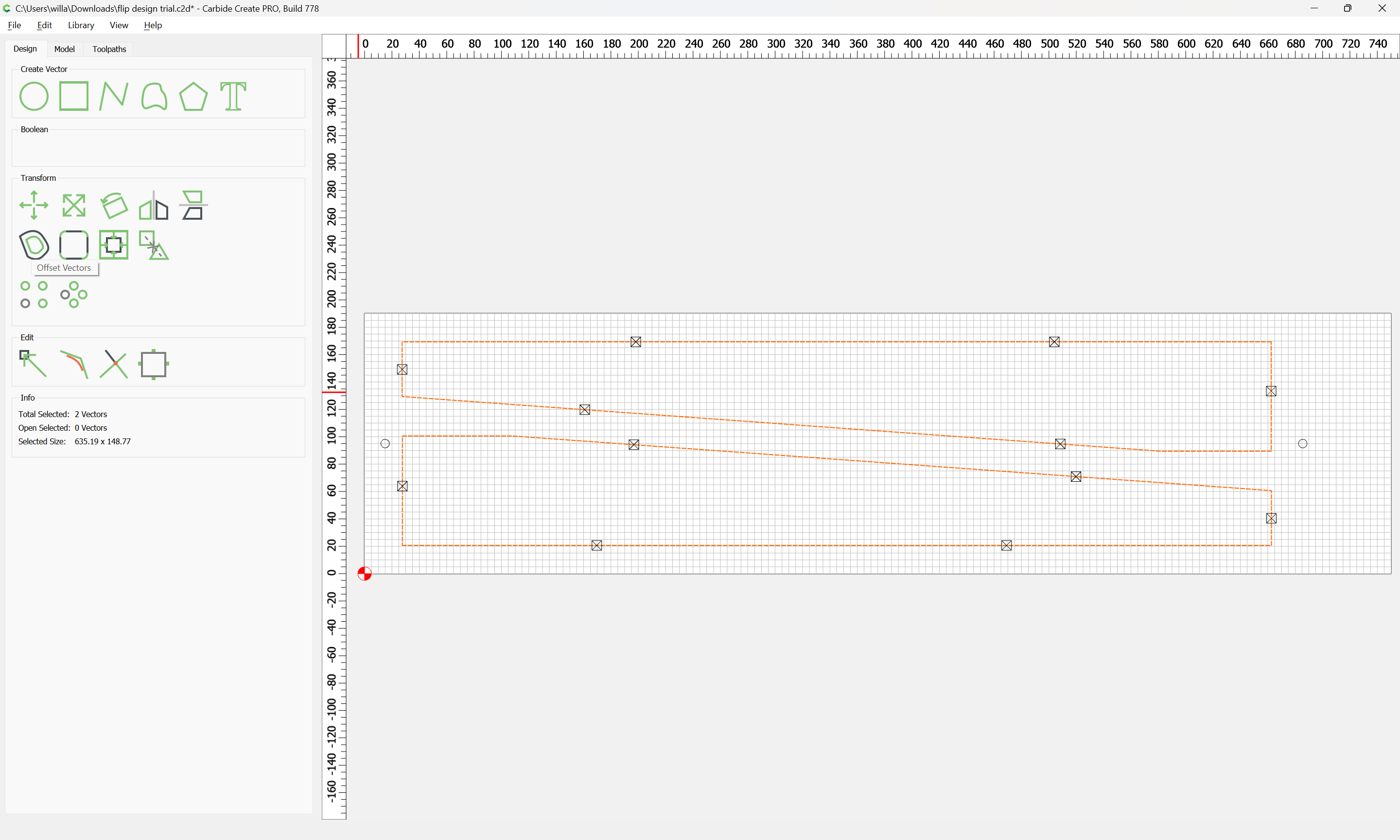
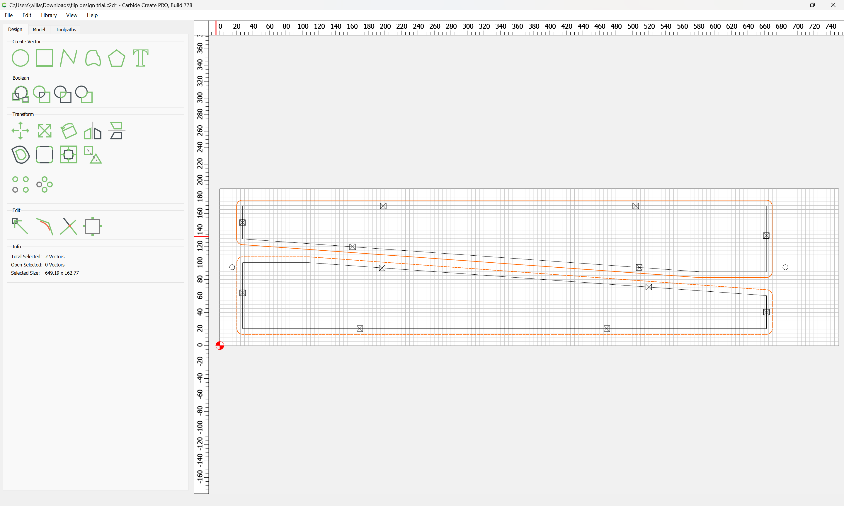
mirror horizontal to create Side B path, then flip the board the x, y coordinates of the starting points are no longer the same as the original, right?
Do I need to make a flip frame, like Kevin did in his tire video?
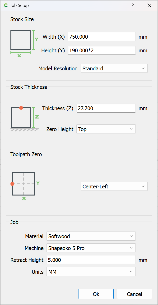
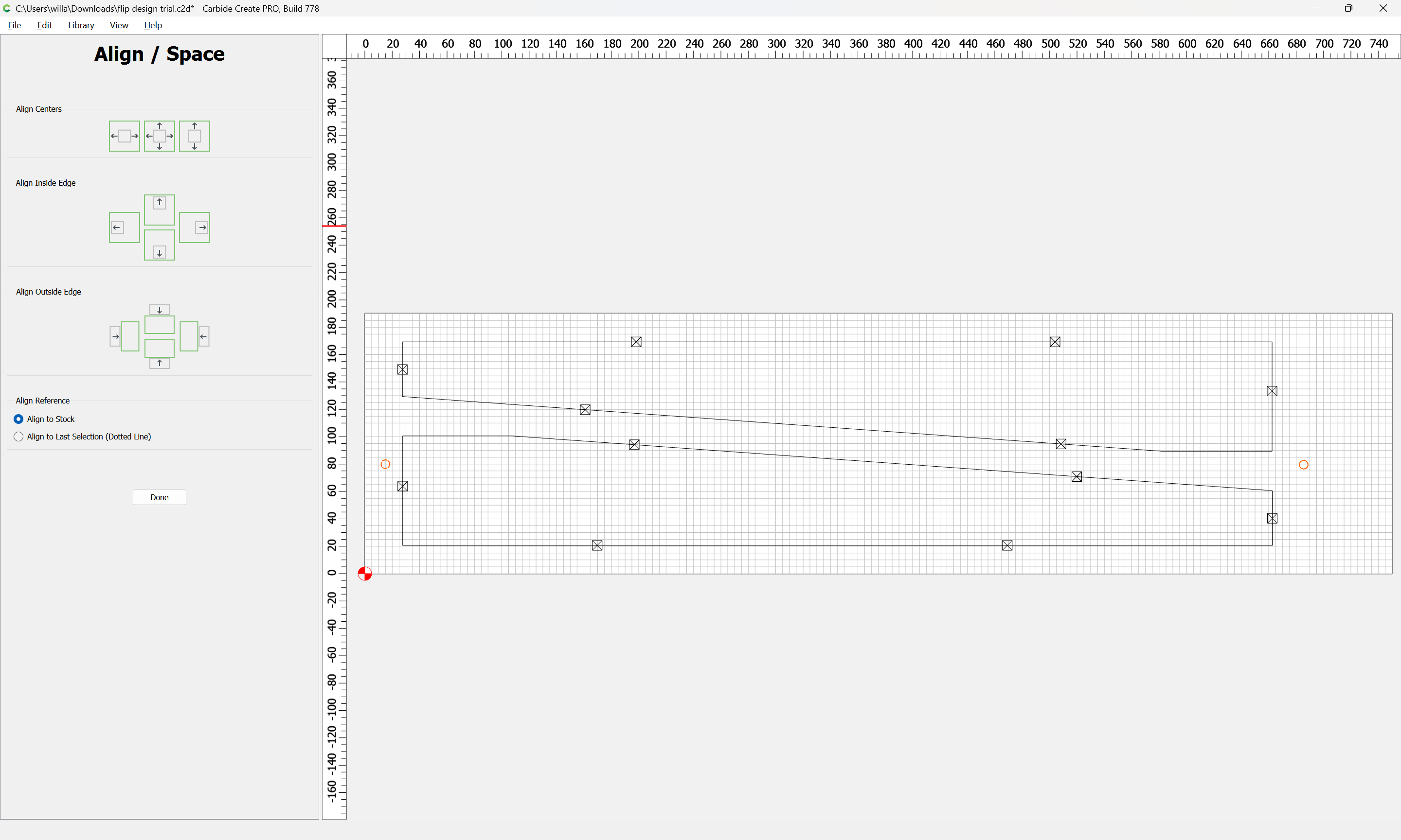
It all comes down to accurately locating the second side for cutting. This is accomplished by knowing the exact size of your stock and having the parts centered within that stock or frame.
Cutting the flip frame with the machine is my preferred method to locate the parts correctly.
This is because my Side 1 operation defines all the measuring and dimensioning. I’m not relying on some outside measurement of my stock on a table saw, for instance.
OR -
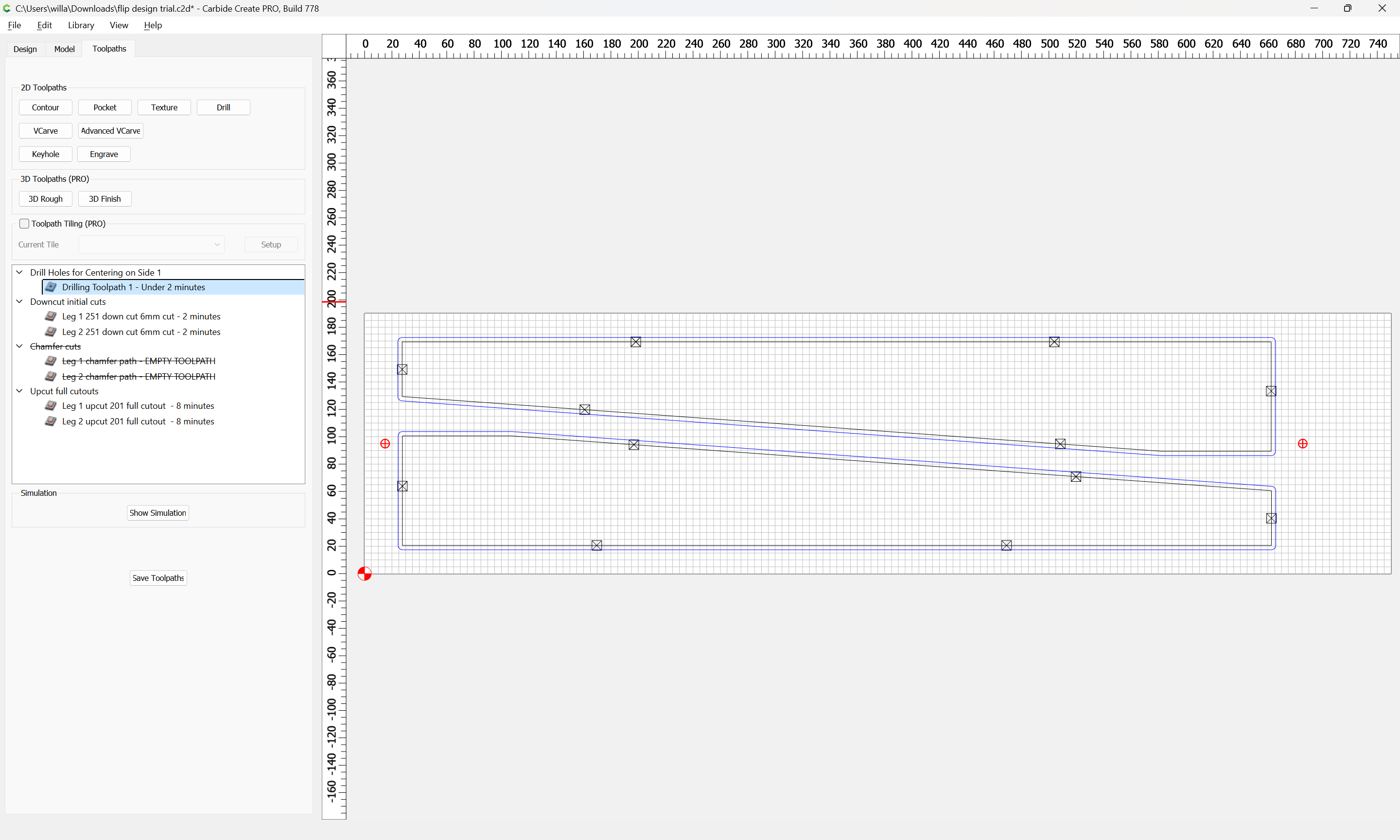
Design your file so that the last step of the first side drills a reference hole completely through the board, in a spot that’s in the waste area
Flip that hole along with the rest of your design when you make your mirror design for the flip side
Then, have the first step of the flip side drill into that hole
You’re ready to cut -
Have a hard edge that won’t move on your waste board and reference one edge of the piece on that. Then you only need to find one dimension to assure you’re in the right place.
Cut the first side - fairly freely - you don’t have to be too particular about where you are, as long as that one edge is securely against your reference fence.
Flip the work - align to the best of your ability, then start the flip side job.
The first thing it will do is attempt to cut (recut) the hole in the waste space. Stop the job as it’s about to penetrate the hole and check to make sure it will plunge directly into the piece at exactly the right point. Adjust zero, if necessary - which will be necessary if your stock isn’t perfectly parallel and square)
Then either restart (if zero had to change) the job, or just let it go from there (if a miracle occurred).
You will be perfectly aligned.
[EDIT] I’ve been told that, if you know the coordinates of the hole, you can type those into the interface to set zero and avoid having to jigger back and forth with the tram to find a perfect zero point - but I haven’t been able to figure that one out.
What I do is measure how far off I am from the hole and then adjust my zero that amount before restarting the job.
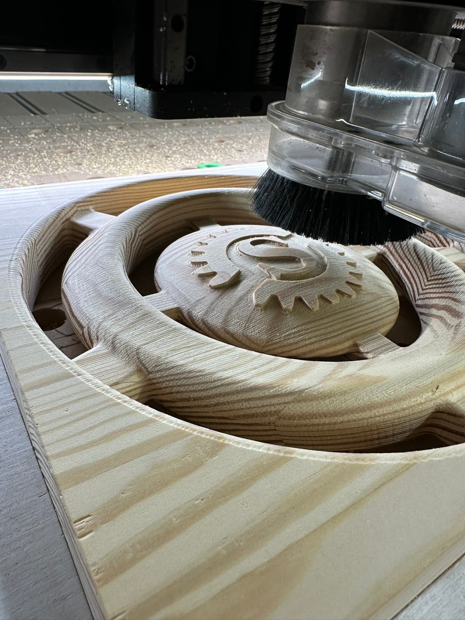
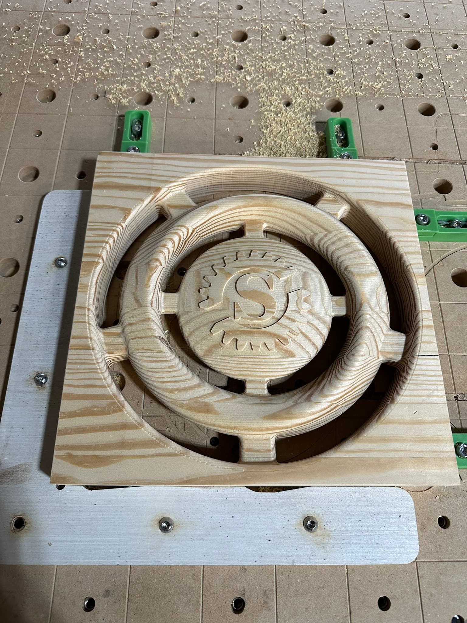
I did a flip project this weekend. This wasn’t a 2D flat part but a 3D Model. The most important thing I found in it was the accuracy of the base stock to what you have drawn. I used a corner square in my set up so that I have a way to make sure when I flip, one side is registered. In this case X axis. Lower right corner was my X0Y0.
Thanks. The circular objects are symmetric and works pretty easily with a corner square. I have a rectangular cut that is asymmetric. Thats what I am struggling it a bit. I guess I jut need to cut it and see how it works out. Its a simple cut otherwise.
Will,
Not sure you sent me the file. Did not see any attachments. Would appreciate is if you can send.
I have been trying to get this to work. So far, its cutting the back a bit off.
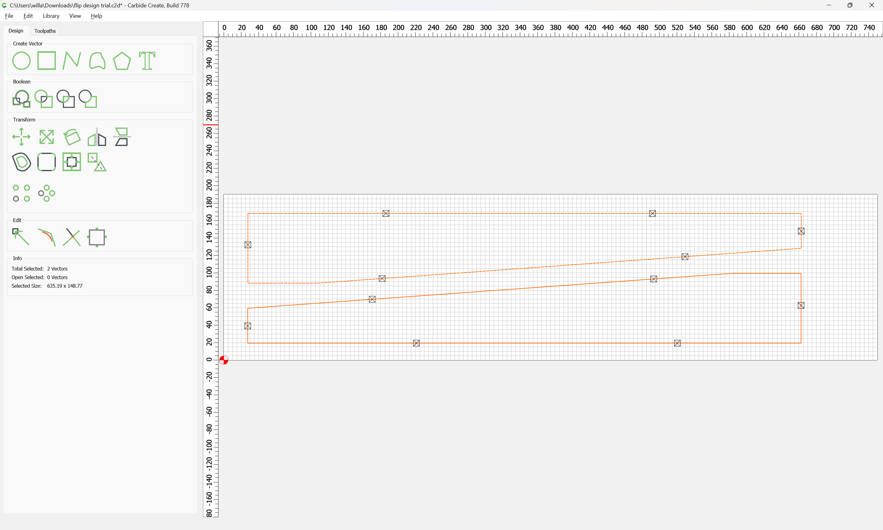
Also, in your original reply to my message you said flip horizontal but your latest says vertical. Vertical seems to make more sense but like to confirm that for sure.
Thanks,
Mani
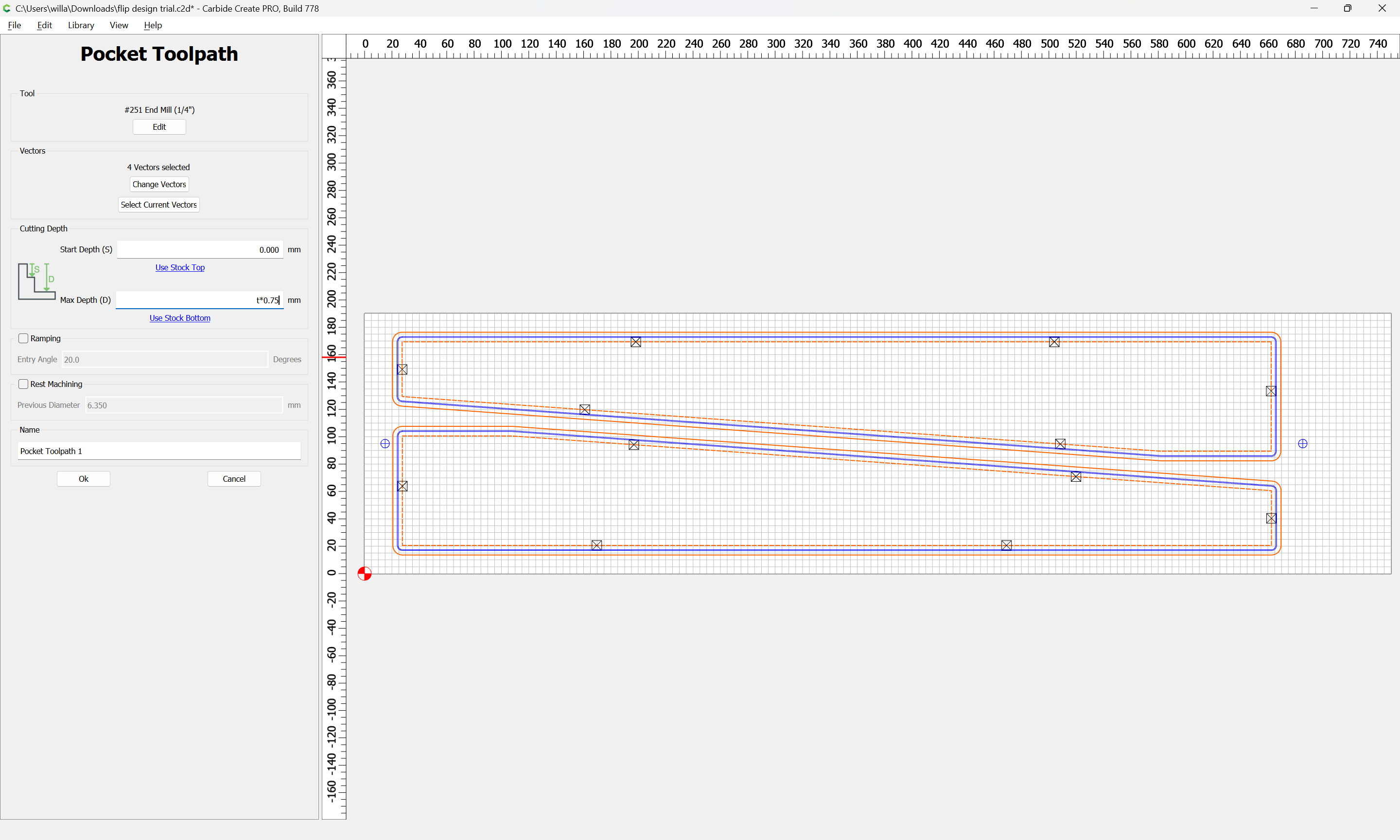
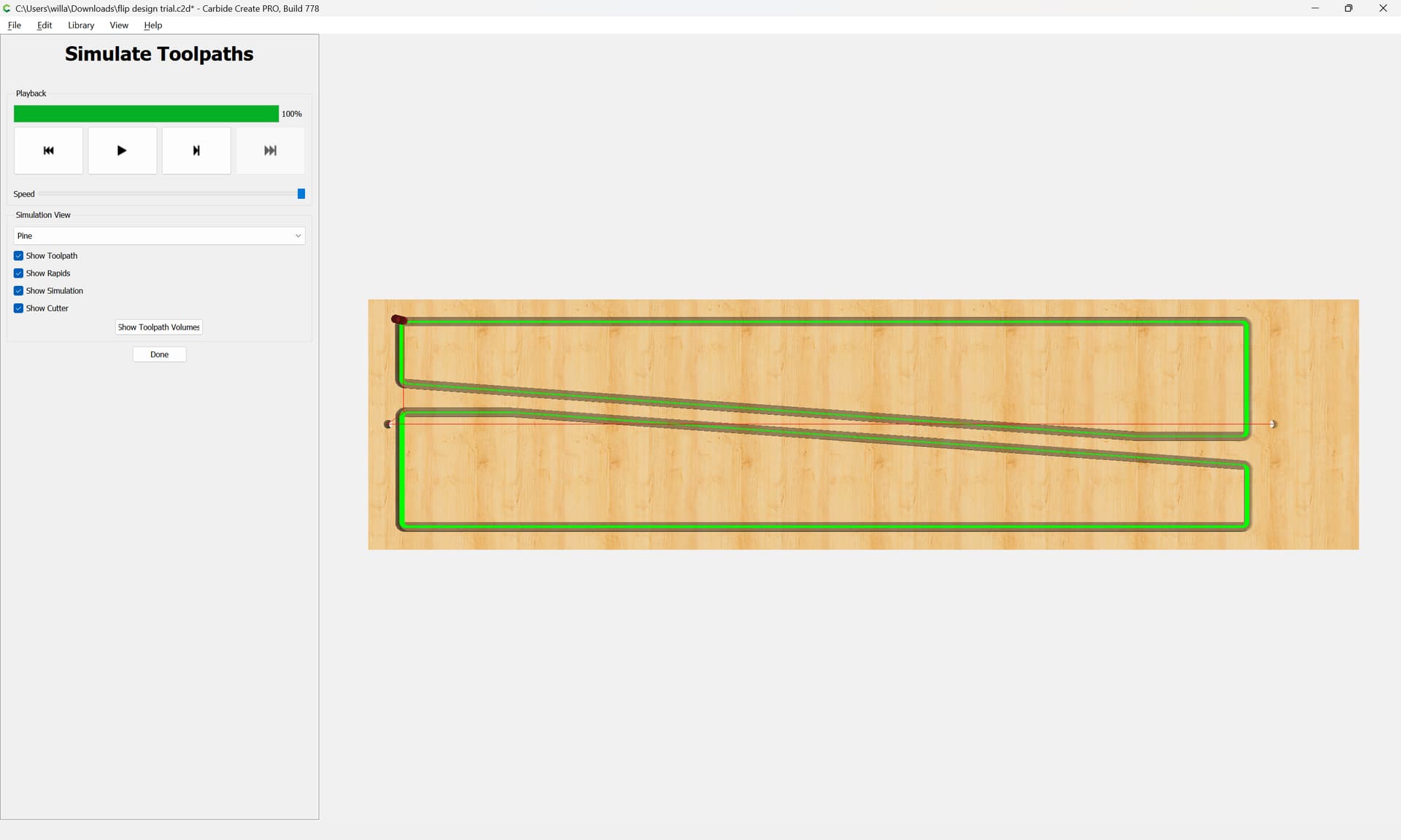
change the full cutout to take into consideration the material — my recommendation would be to make the first side operation remove 3/4ths of the material, and to do it as a pocket:
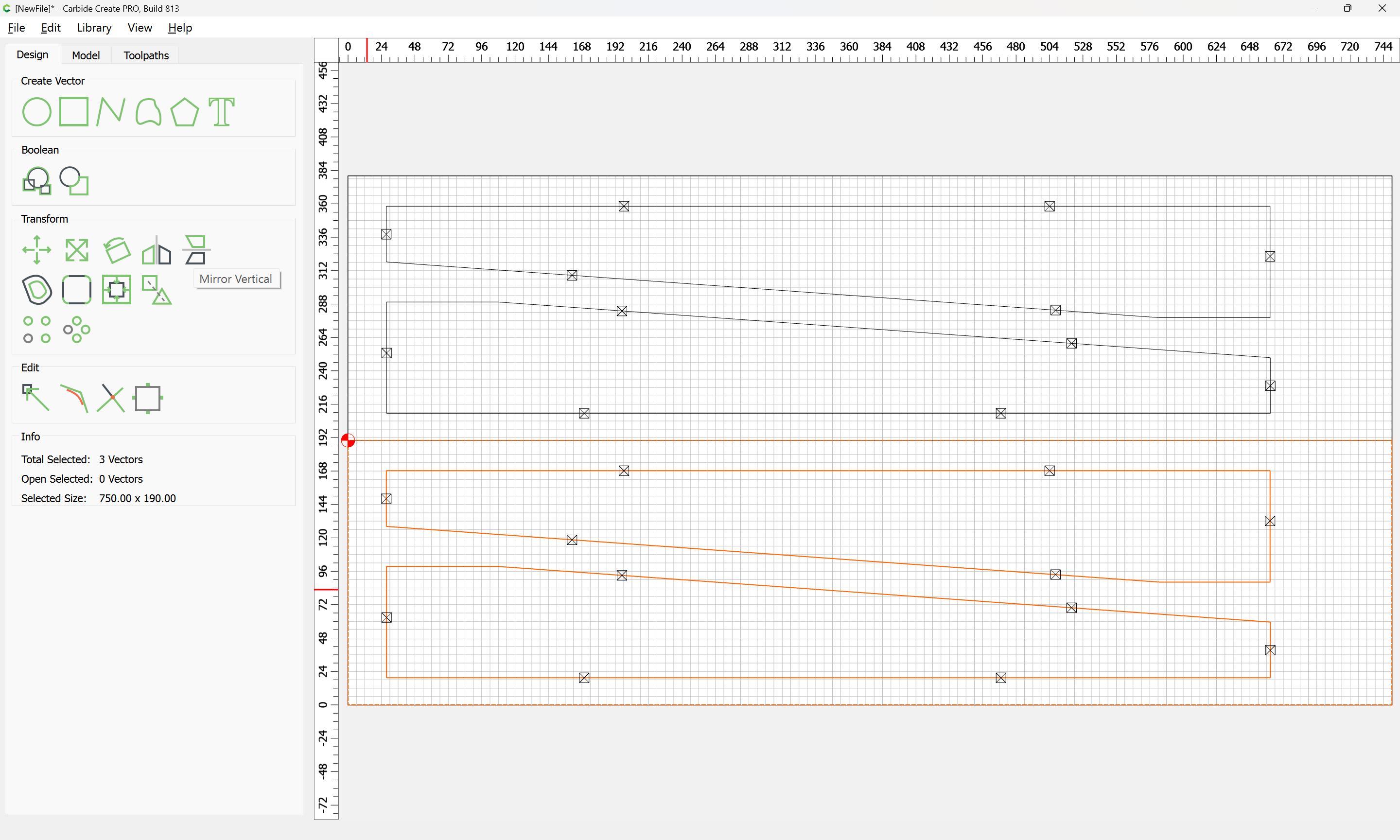
Then, for the second side you would machine the dowel holes, insert the dowels, flip the part over, if need be, re-zero at the top-left corner making that change, but arguably, the origin shouldn’t need to be changed — the problem of course is center doubles any alignment error.
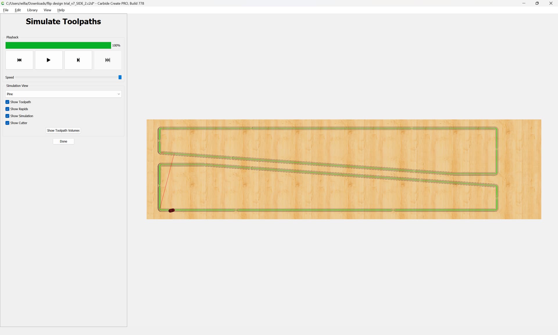
disable the pocket cut and set up a cut which makes the finishing cut:
I’ll just point out that, if your stock at least one pair of parallel sides (which is easy, if you have a tuned table saw), you only need one reference hole - and you don’t need dowels that will register it. The method I described, above, will easily position your flipped piece perfectly. For this project, I did 80 differently shaped, non-symmetric pieces with this method and it worked perfectly every time.
Thank you so much for taking the time to give these detail description. I will digest this abit and give it a shot. I also asked for support from Carbide 3d as you suggested.
Gary,
Thanks a bunch.
Now that I think about it, I am not sure my stock had parallel sides as I was using scrap plywood. Never thought about that. This might explain why my cuts were going off. I think the side A cut might be the issue as the flip frame I used is cut by my machine. I will try a squared work piece.
I try to eliminate as many calculations and measurements as possible, so I try to use techniques that don’t rely on perfectly square corners or perfectly centered designs. But a parallel board is a given with my saw…so since I use a fence on one side, when I flip the stock, I’m sure that the piece is not skewed “up and down”. Then I just need to make sure the bit plunges directly into the hole on the second pass to set my zero - and it works. it takes a little longer, because you have to figure out how “off” it is, and adjust your zero accordingly…but it does work perfectly.