looking for video or help with the model shape feature. Winston briefly covered it in his knife tutorial, but gave no details. for example what is round vs angle vs flat? also, when I go to simulation, it shows up very tiny on the screen, zooming in usually overshoots and then its lost. and I cant seem to rotate the image to see it at different angles. is that normal?
ploughboy scales 3d.c2d (140 KB)
There is some pretty good reading at Introduction | Carbide 3D Guides
See:
I wrote up a bit at:
and c.f.,
1 Like
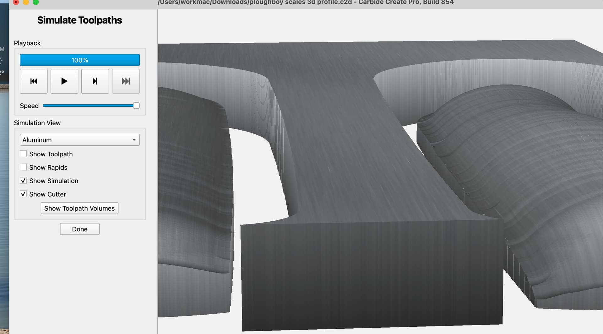
Thanks, The information seems helpful, but i cant confirm the adjustments to settings because the image in “show 3d” is so small, and i cant manipulate it correctly, and cant even change the color to beech.
Any suggestions?
Ok figured that out, i was selecting both scales instead of just one. Whew
Now, can i apply a texture to a curved, extruded surface?
Lots of questions. In my design i profile the knife scales and in toolpath i can select a flat bottom 1/4 end mill with speeds and feeds etc. But now that i have the extruded model the way i like, i dont see where i change the bit to say a ball end mill that would be more suitable to 3d carving. are they supposed to be 2 seperate files? one for profile, the 2nd for 3d?
ploughboy scales 3d.c2d (760 KB)
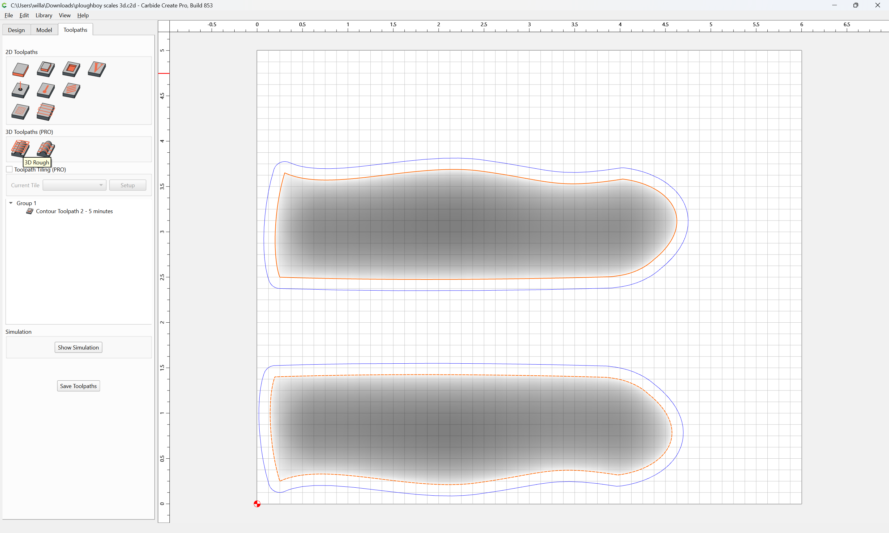
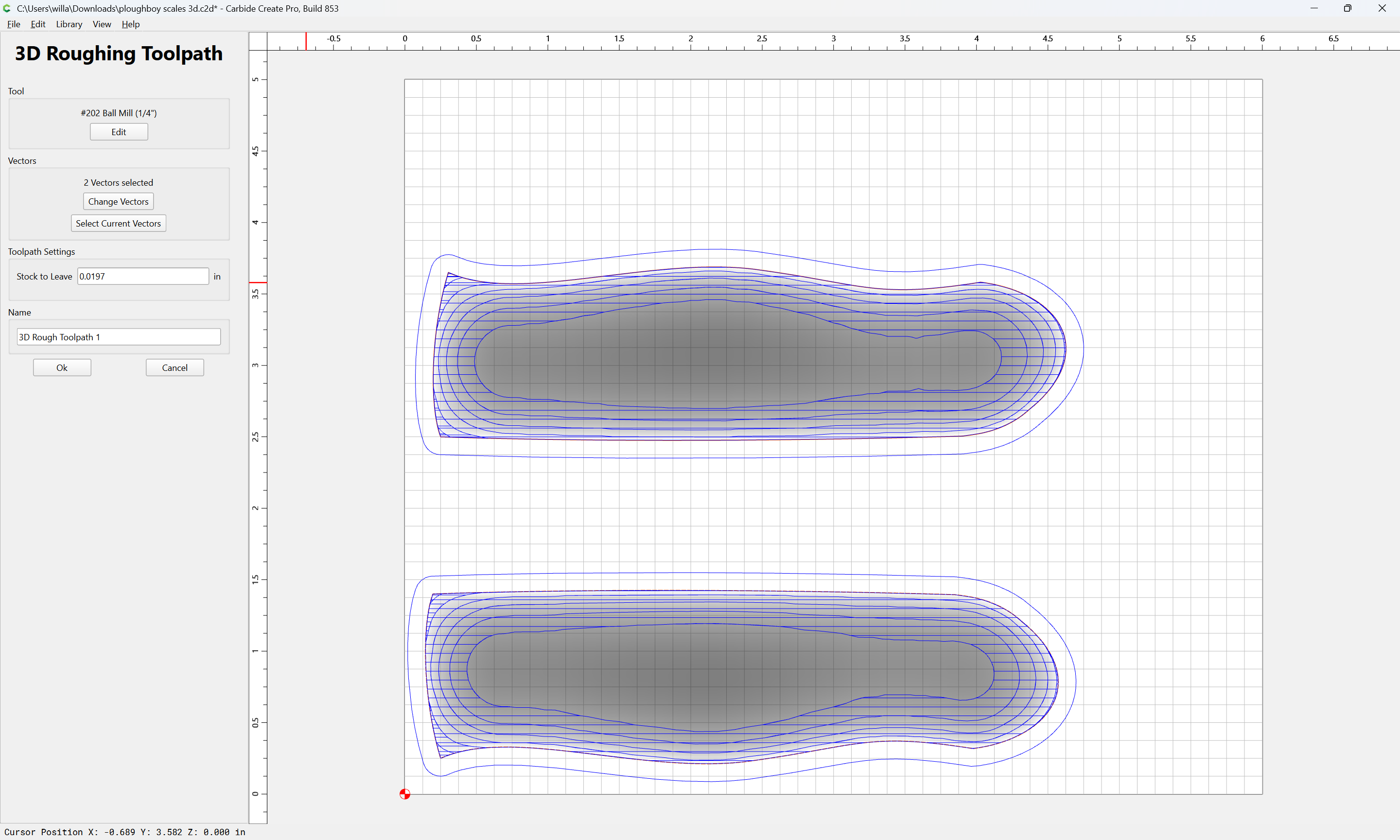

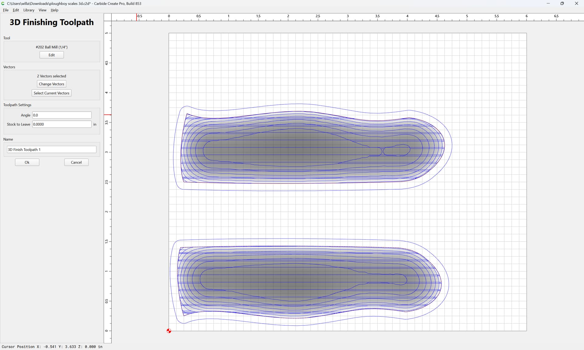
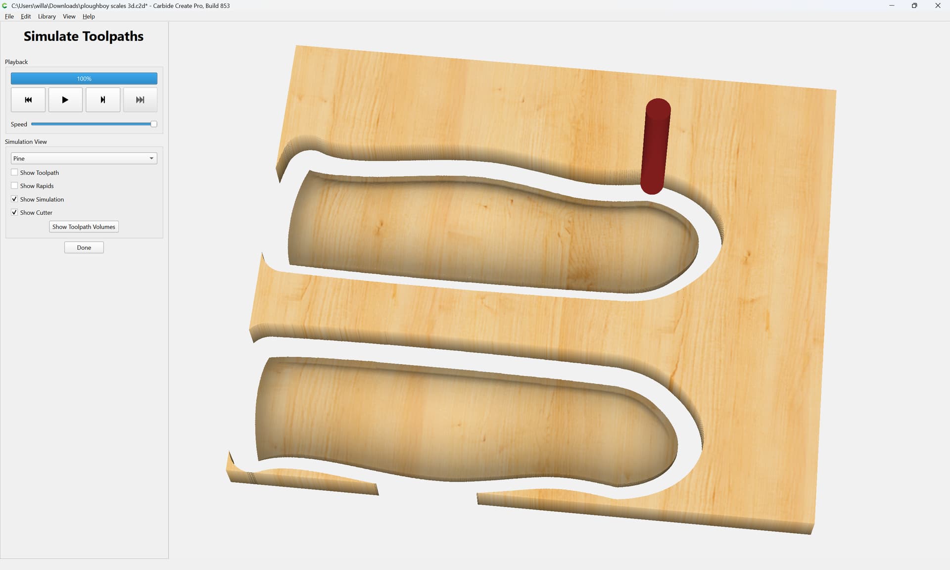

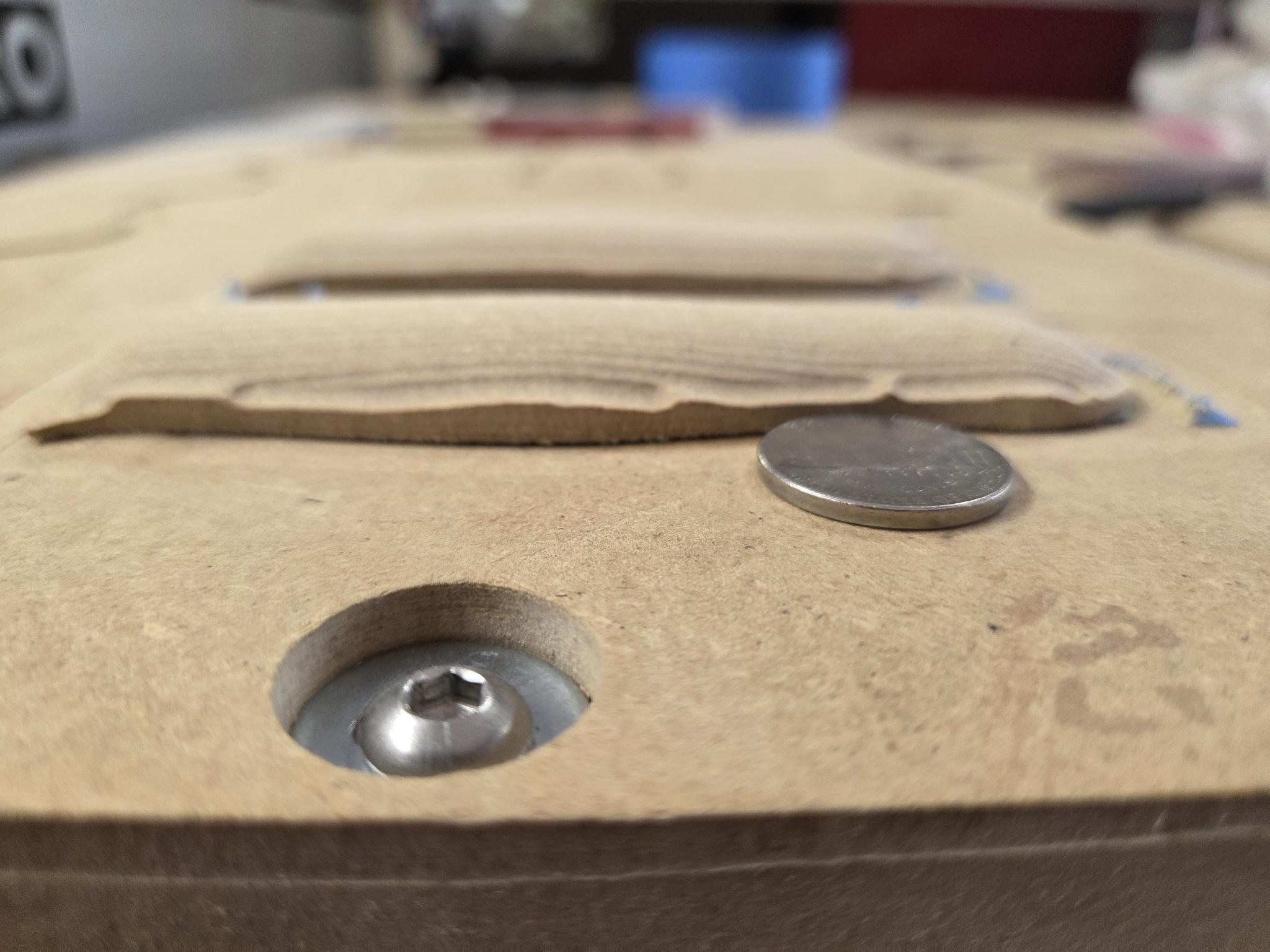
i guess the only way to get rid of the lines from tool path is to infinitely reduce the stepover? but what about the unfinished edge where the nickel is?
Good match for the 3D preview in Carbide Create:
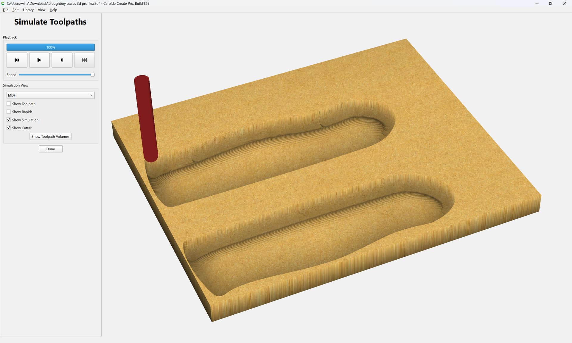
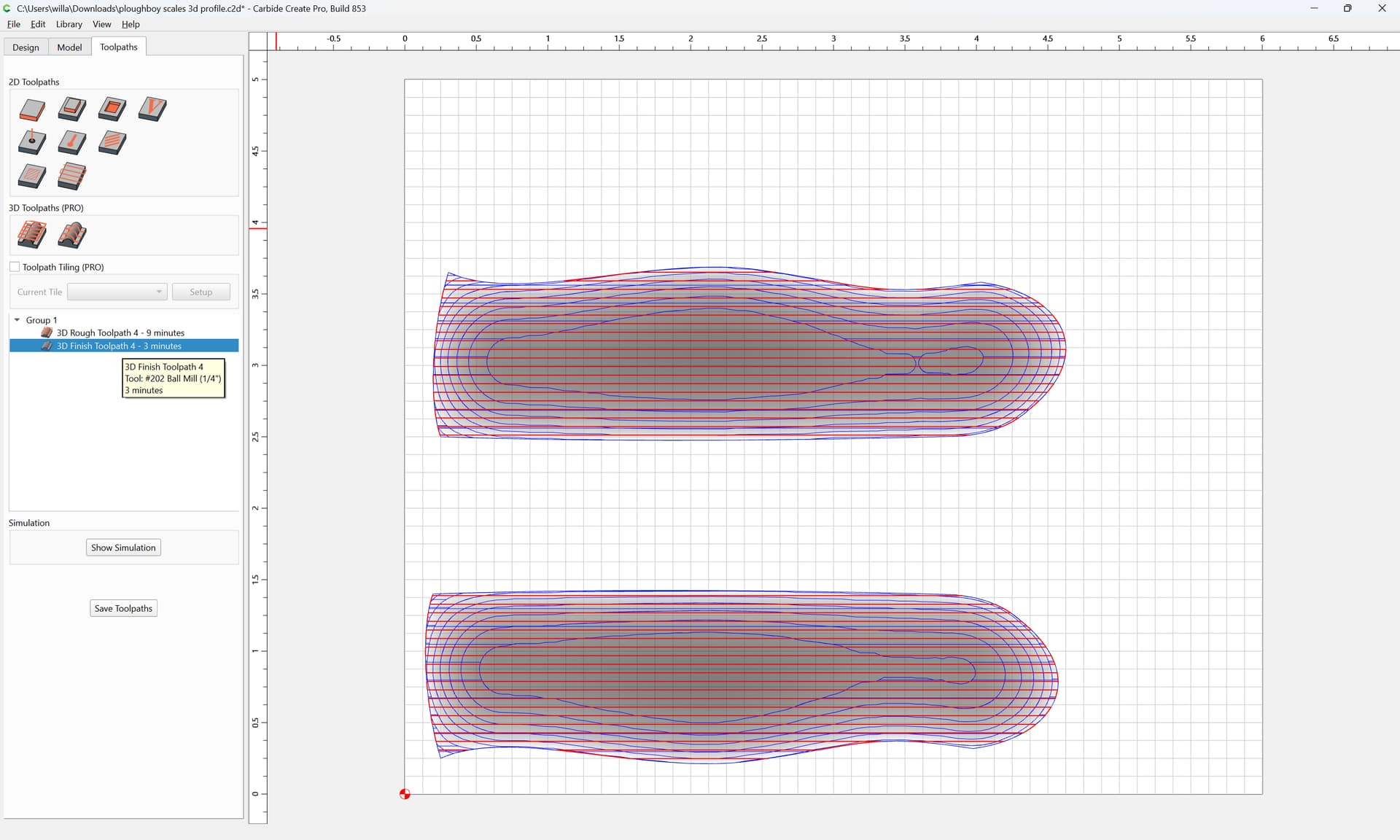
your 3D Finish is only 3 minutes:
The stepover is 0.06"
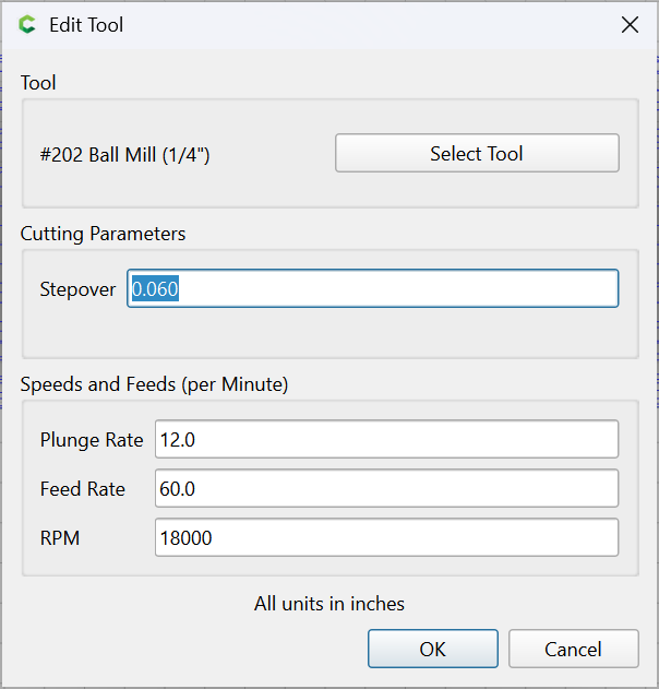
If you reduce that to 0.01:
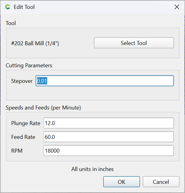
the 3D Finish time goes up to 16 minutes which pays off:
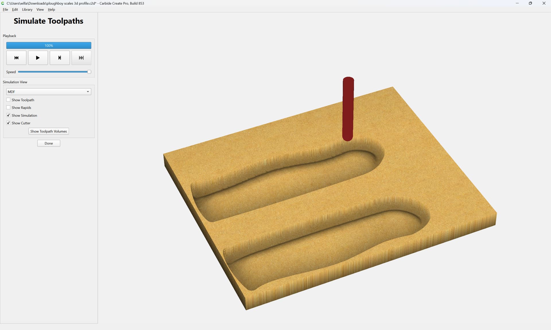
understood, but that wont fix the unfinished perimeter, like where the nickel shows.
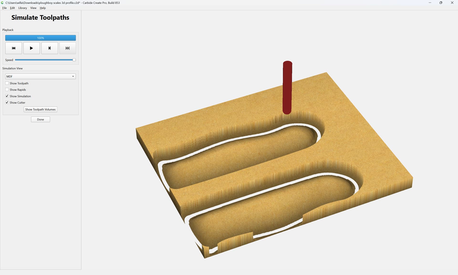
To finish cutting the perimeter adjust the distance around the 3D model of the geometry used for the toolpath:
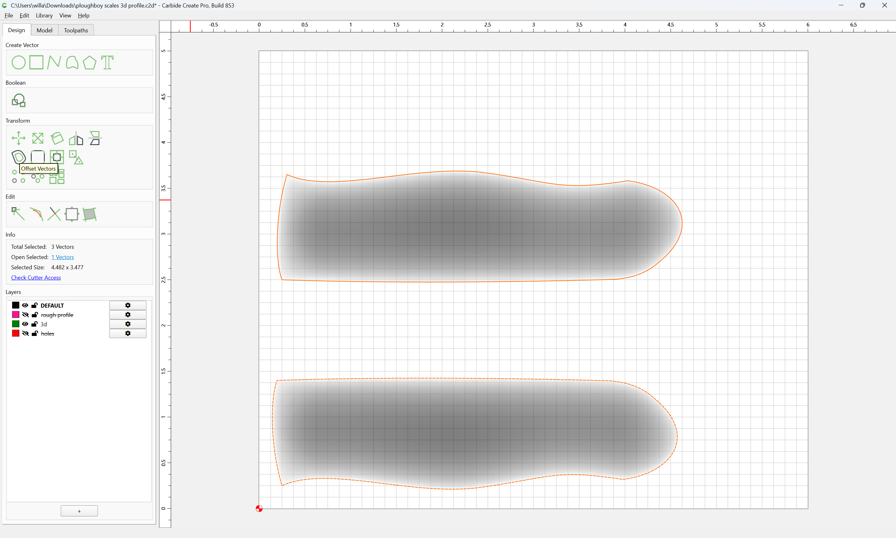
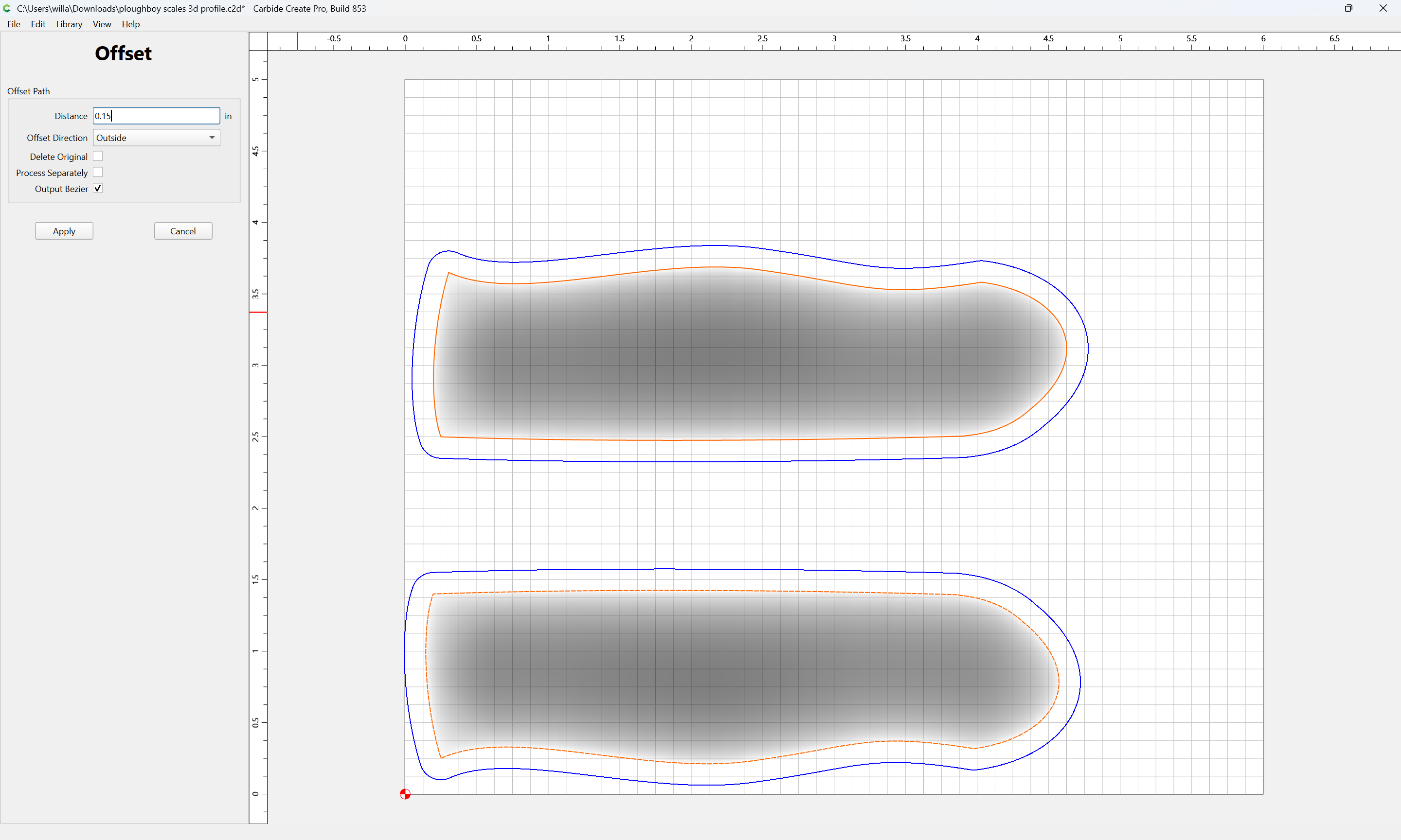
1 Like
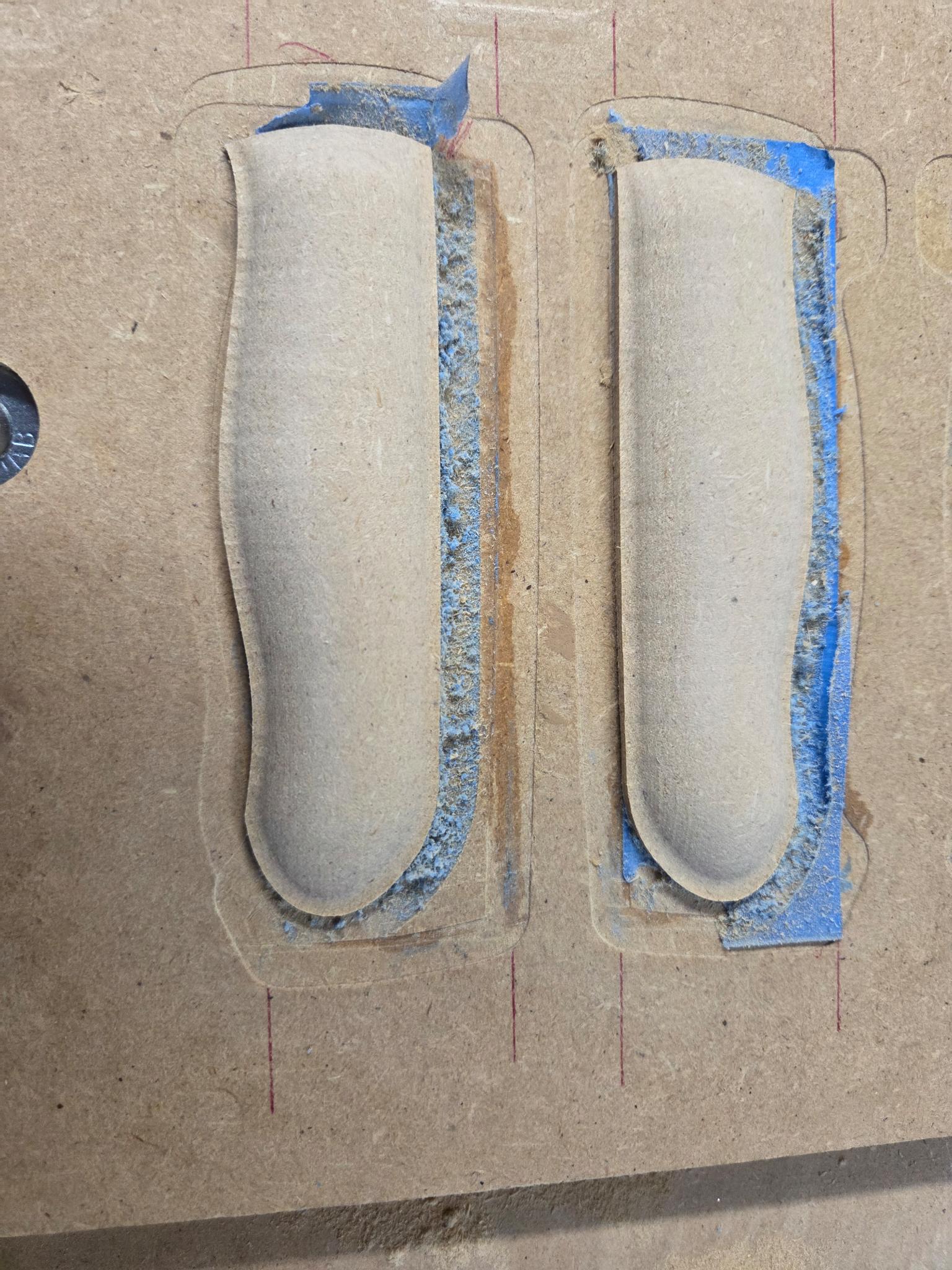
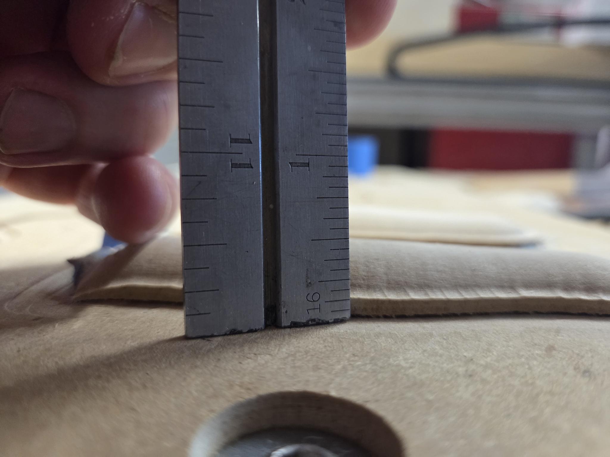
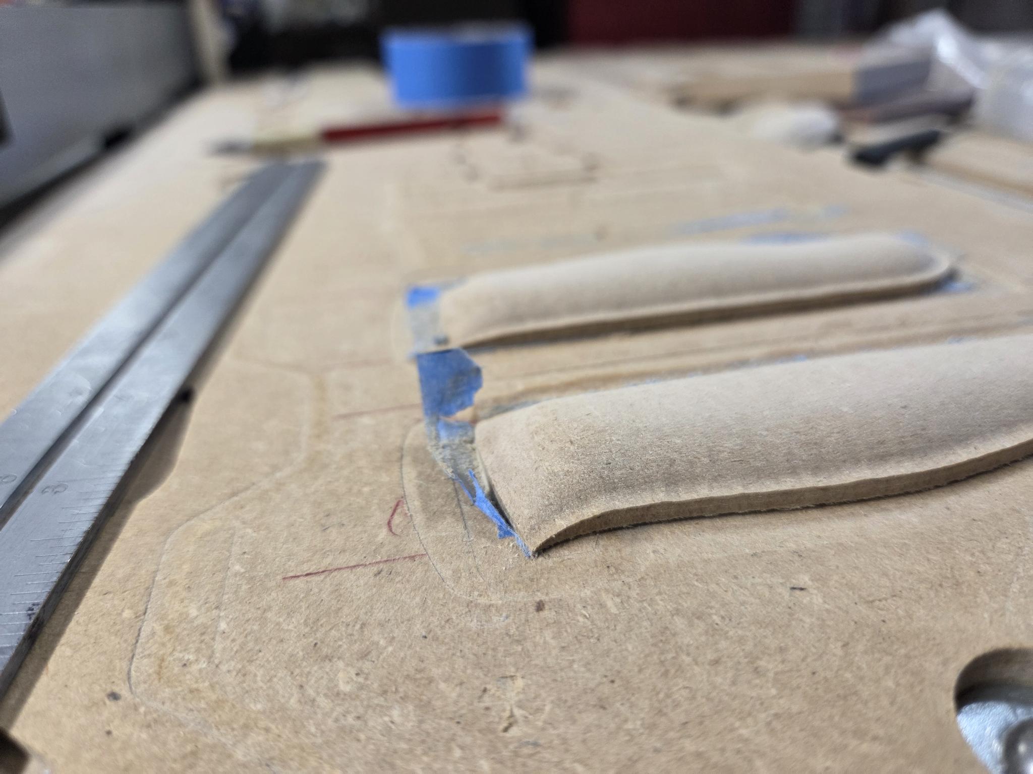
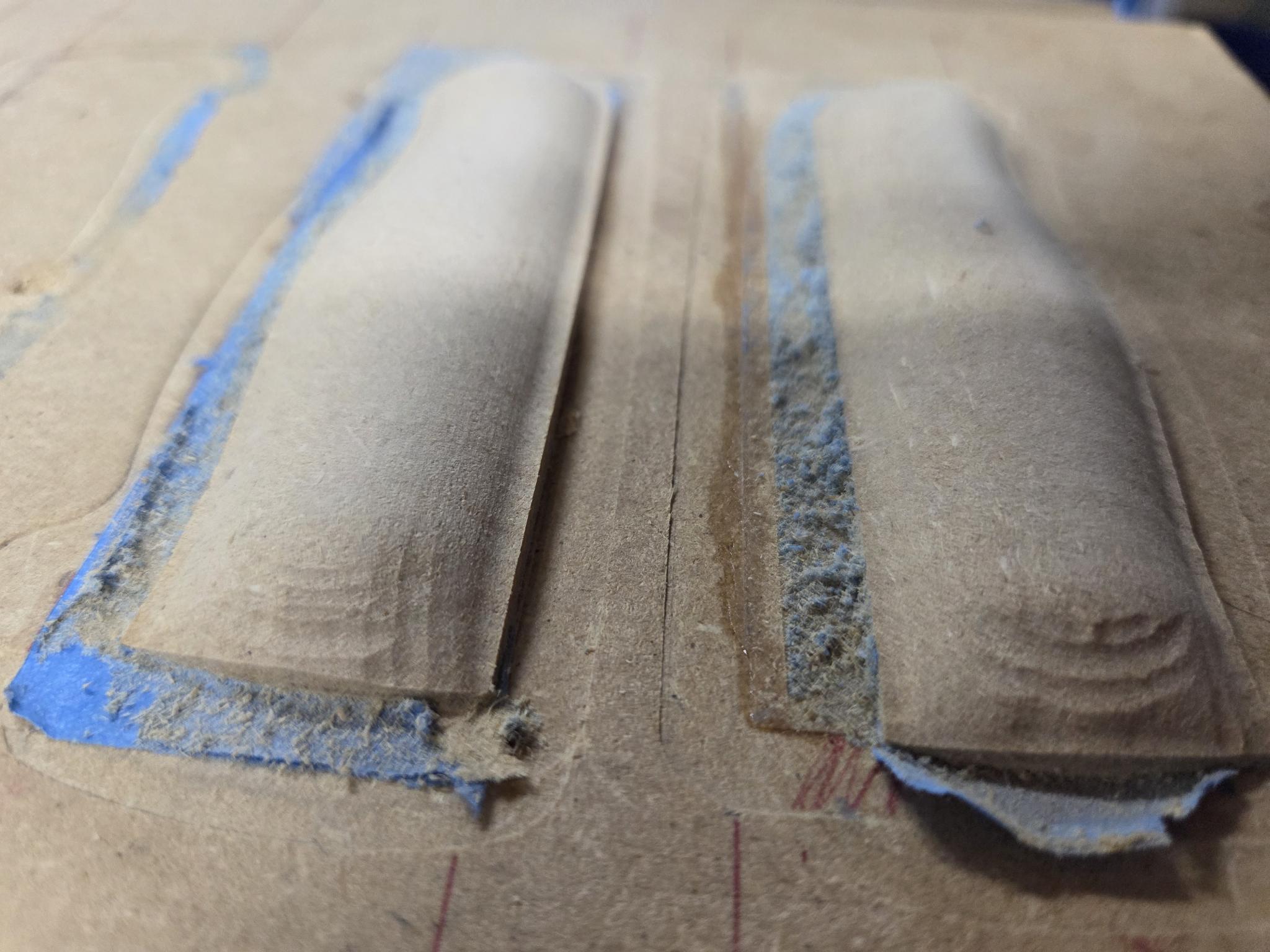
ok i made the suggested adjustments which eliminated the “stripes” and the finish is much better. however, there is still a “flange” of sorts around that is pretty consistently about 1/8” thick and about .100” wide. Only one corner of the scale comes down close to zero. And the ends of the scales were untouched by the finishing toolpath.
ploughboy scales 3d profile.c2d (968 KB)
That is because you are still using the two vectors on the layer 3D:
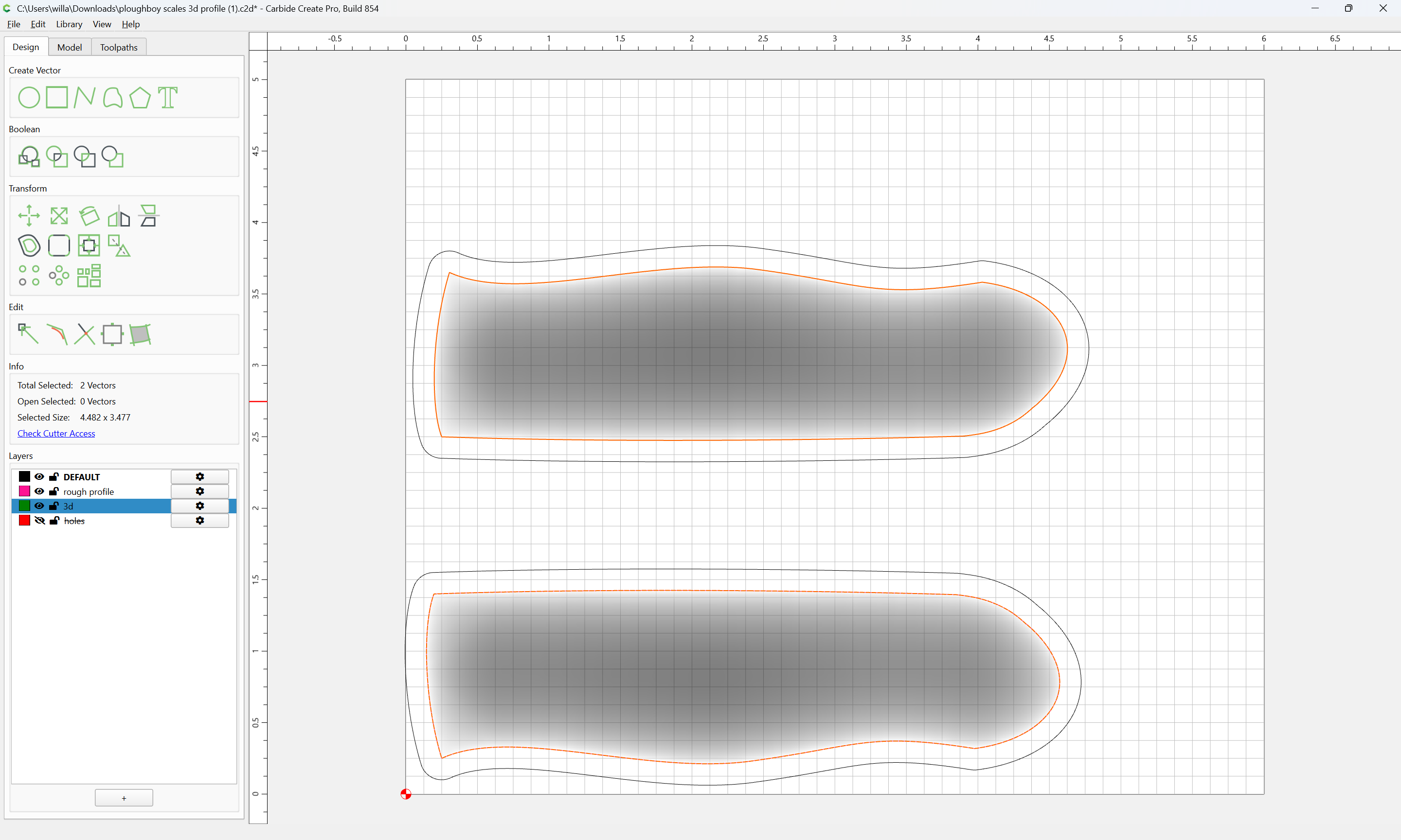
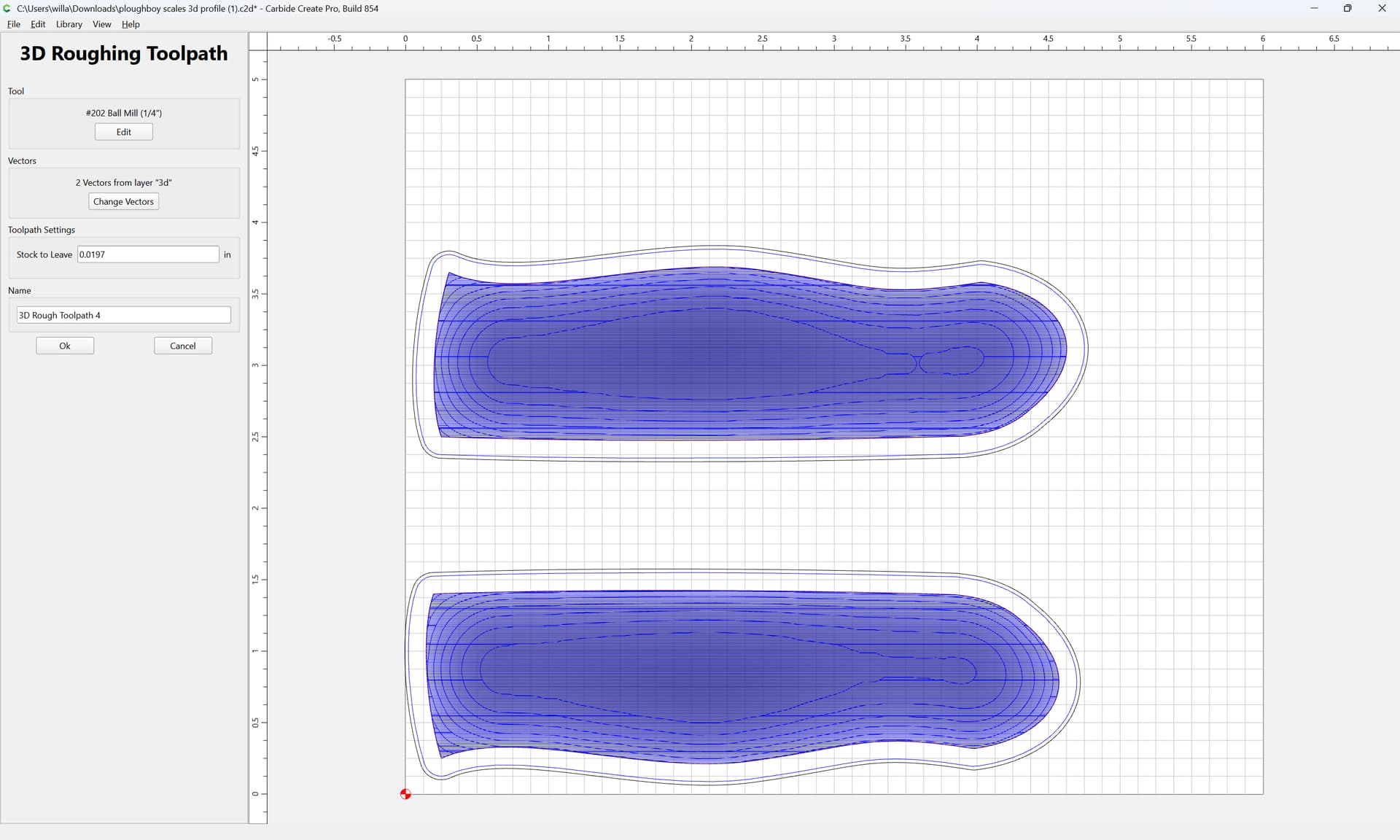
If you change to the offset geometry:
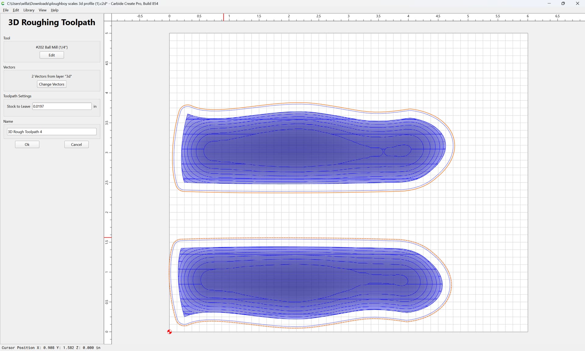
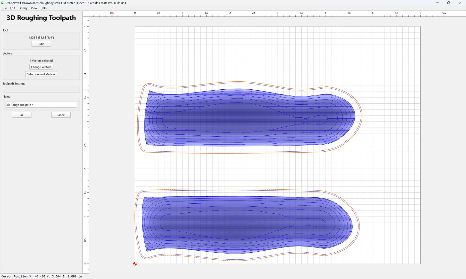
then you will get the desired result:
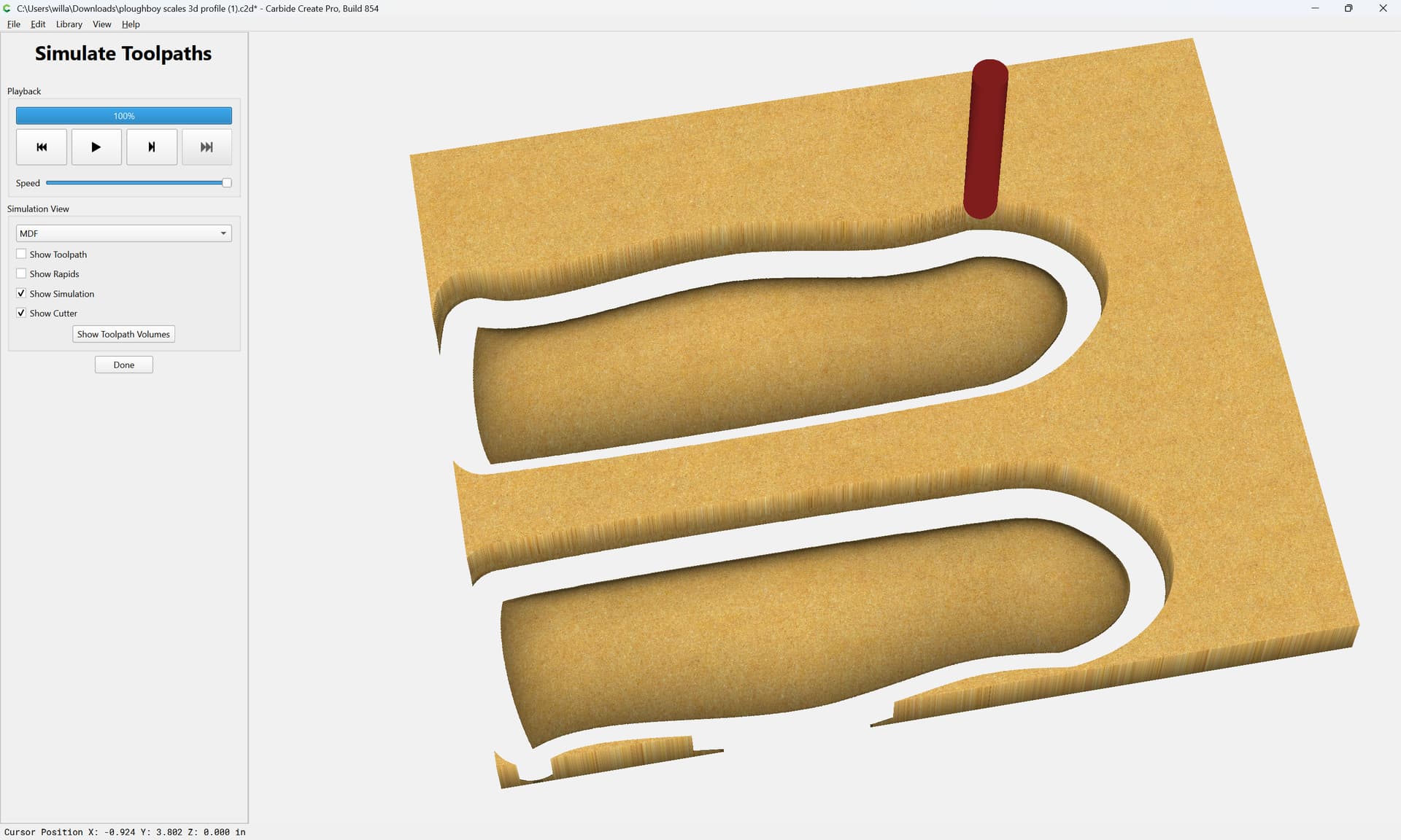
3 Likes
Sorry, im not following what your saying?
I should have 2 layers, one for each offset vector?
If you have geometry exactly around a 3D model:
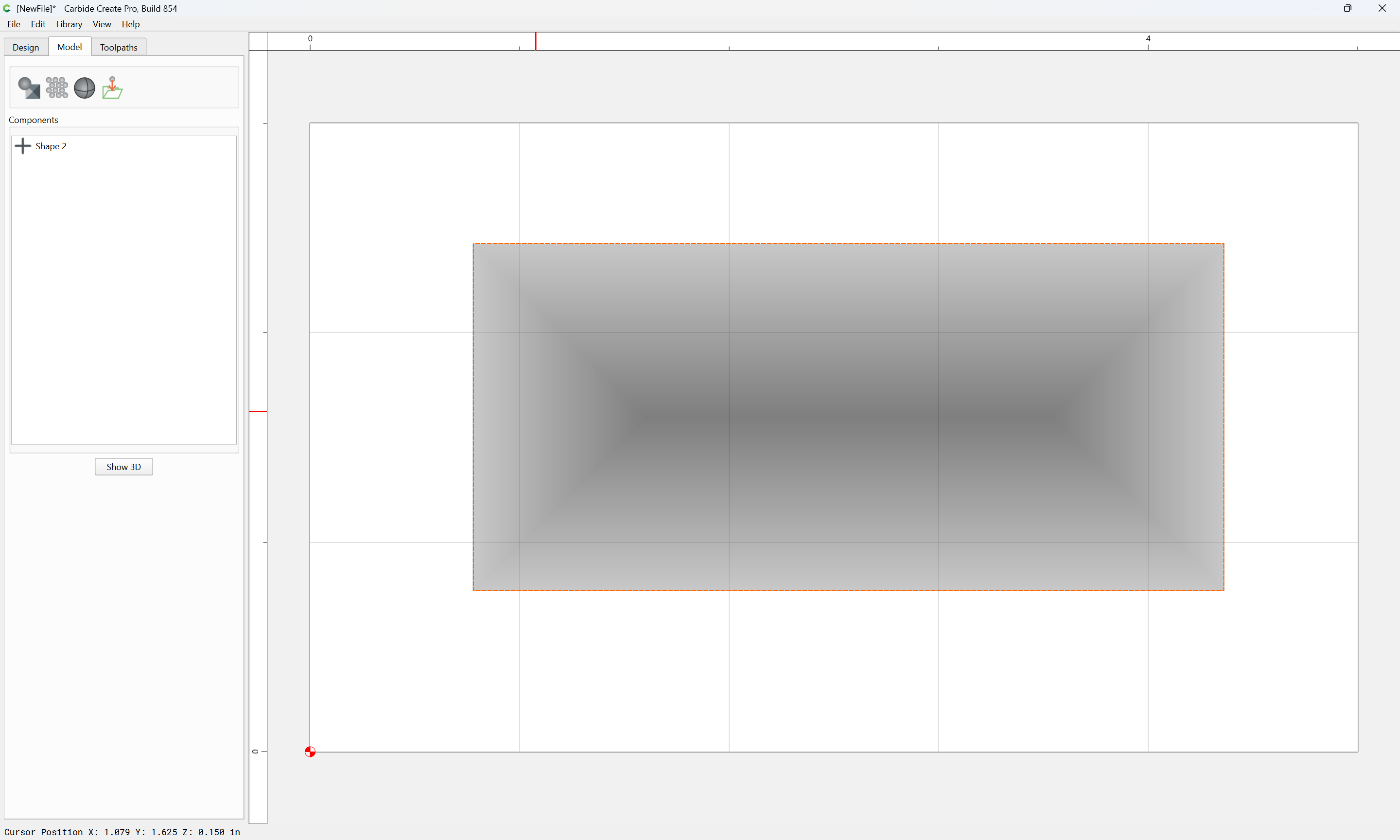
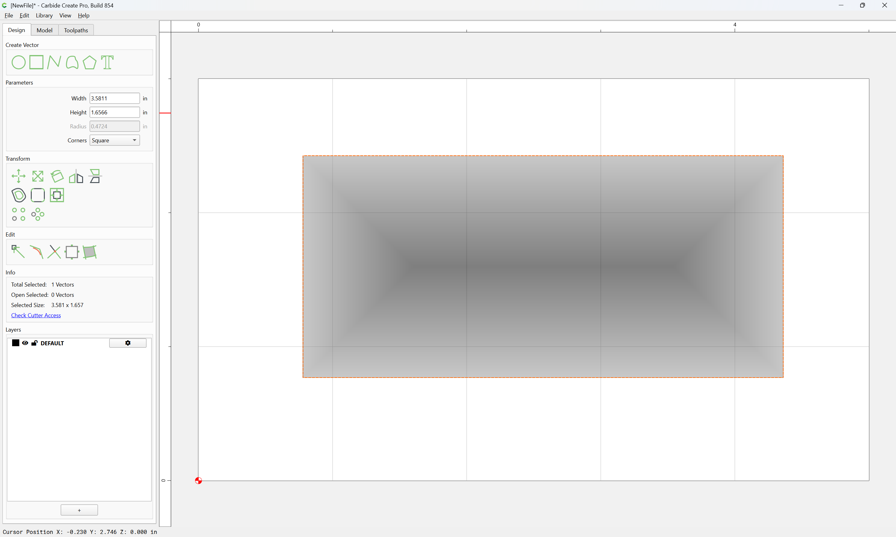
Then the 3D toolpath will only be able to cut up to the edge of that 3D model:
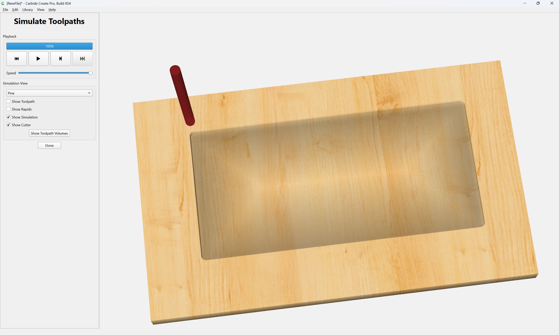
If you increase the dimensions of the geometry:
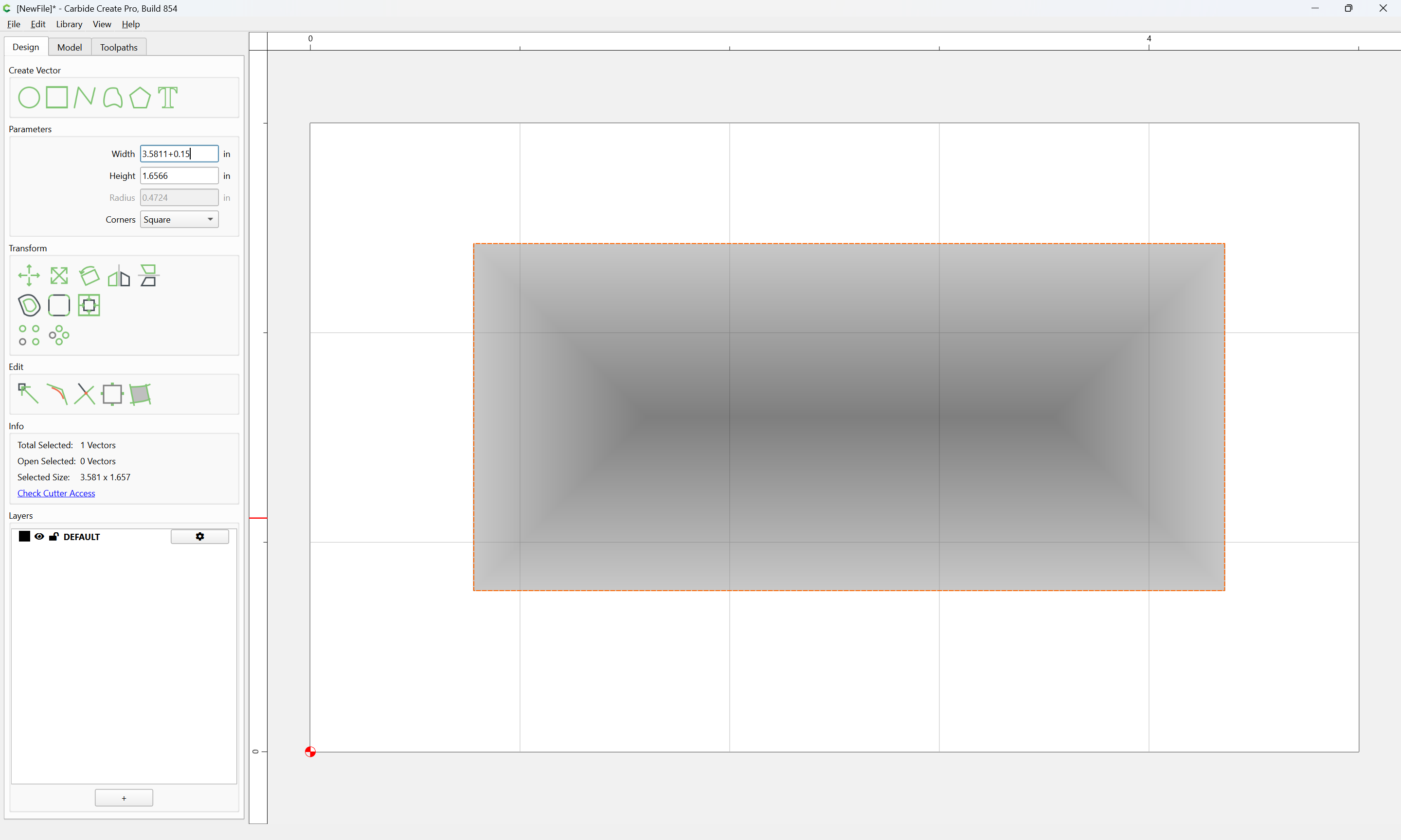
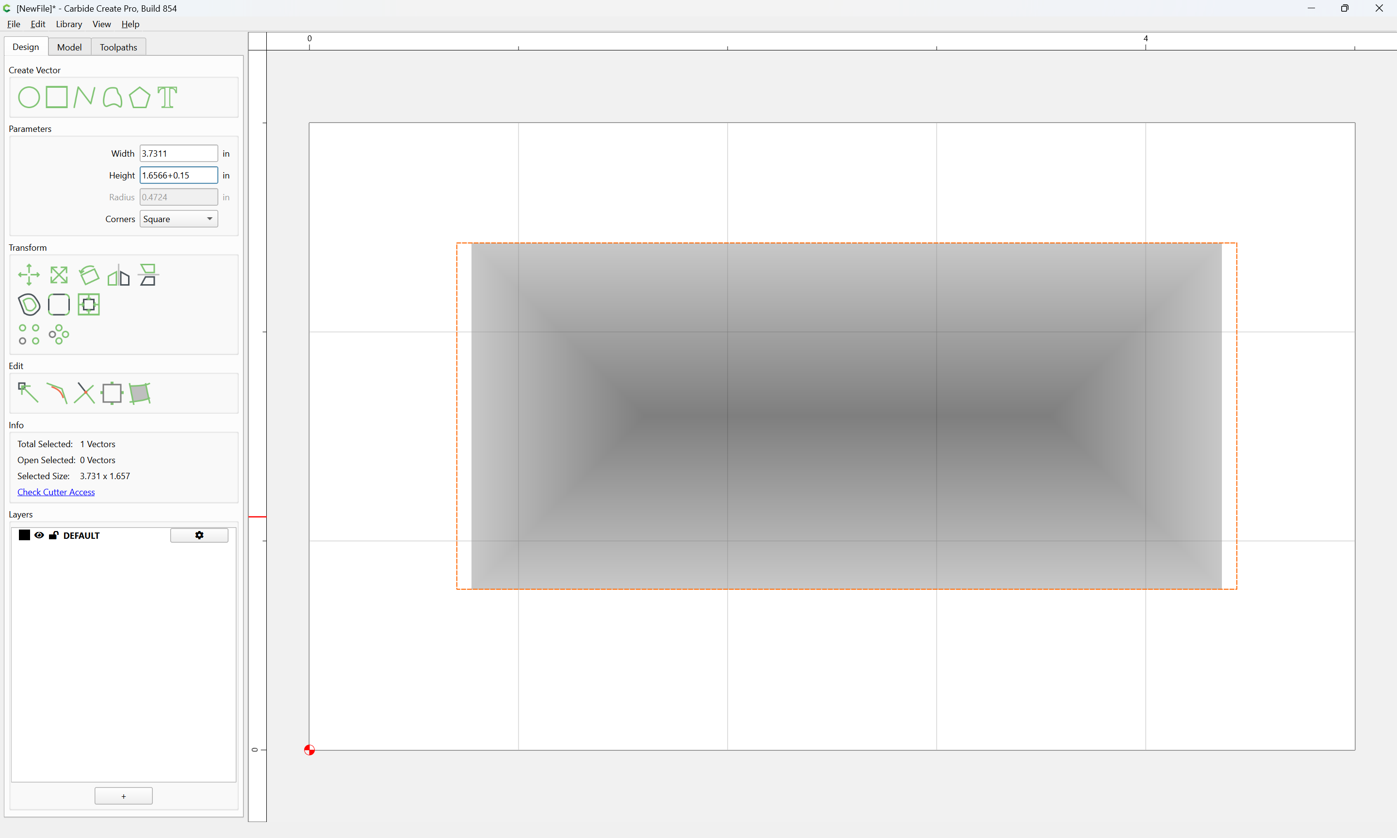
that will then allow access to the perimeter of the design:


within the limits of the shape of the tool — it may be necessary to add a square tool:
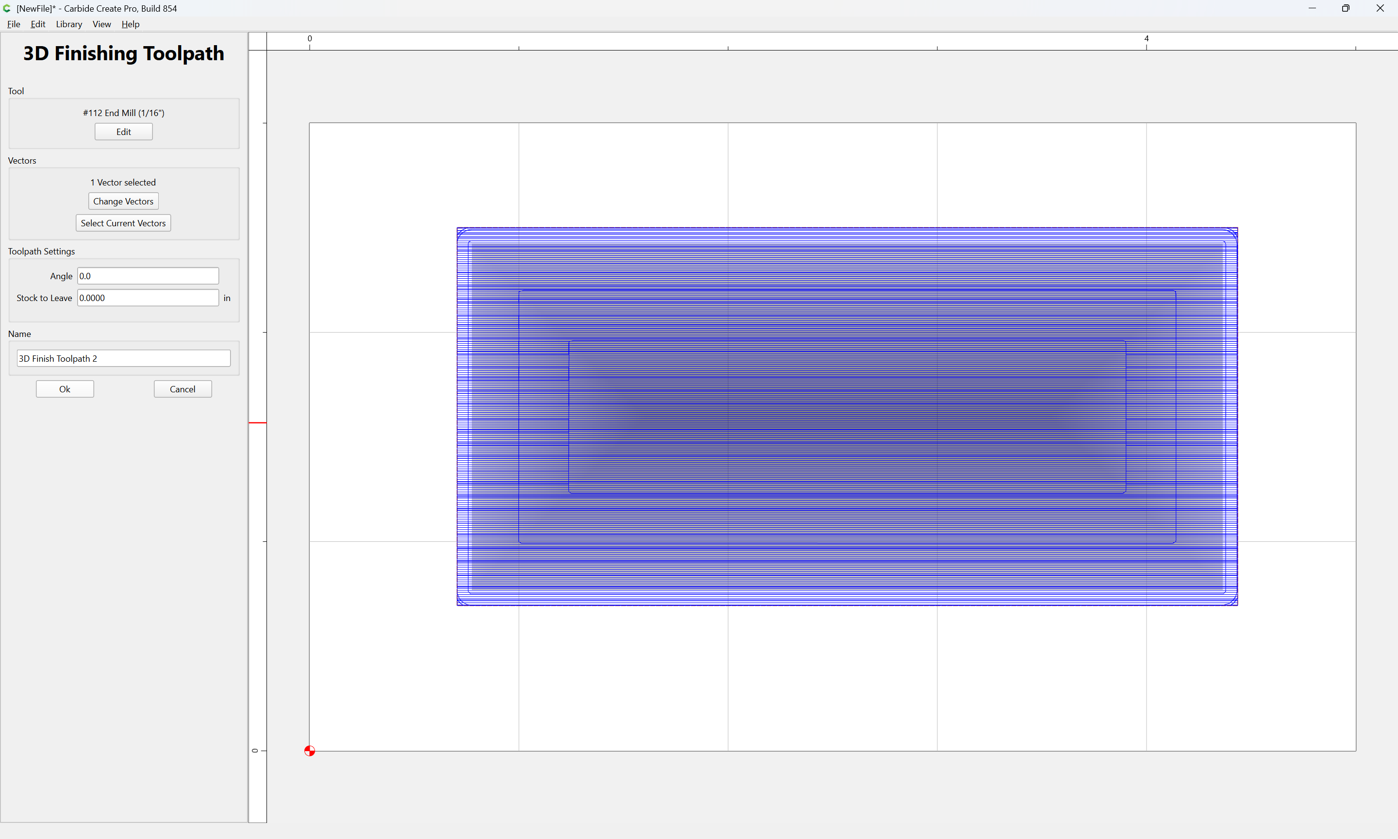
and to adjust “Stock to Leave”
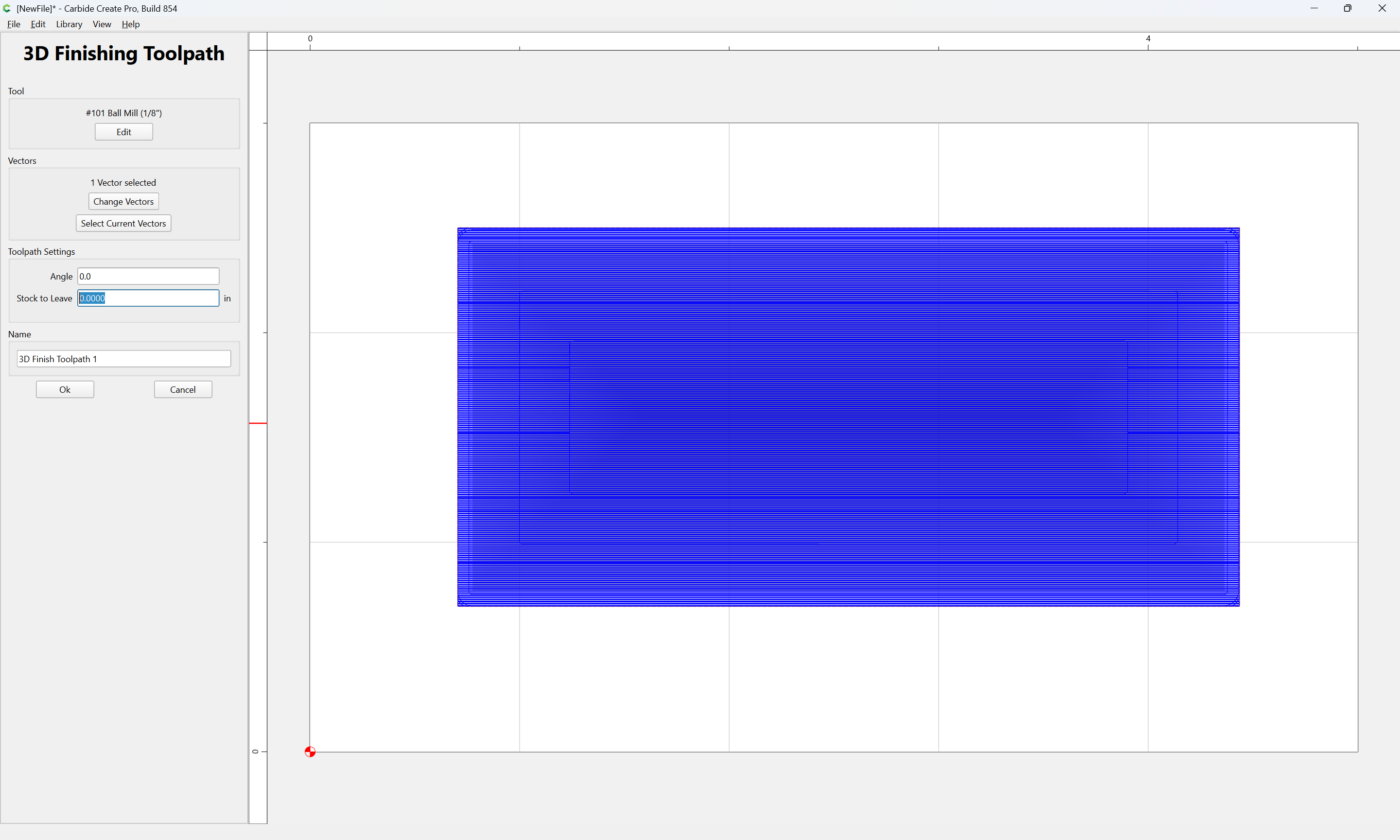
for discussion of that see:
When a tool which is able to access the entire perimeter of the design is used with geometry which allows access, then the cut will be as expected:
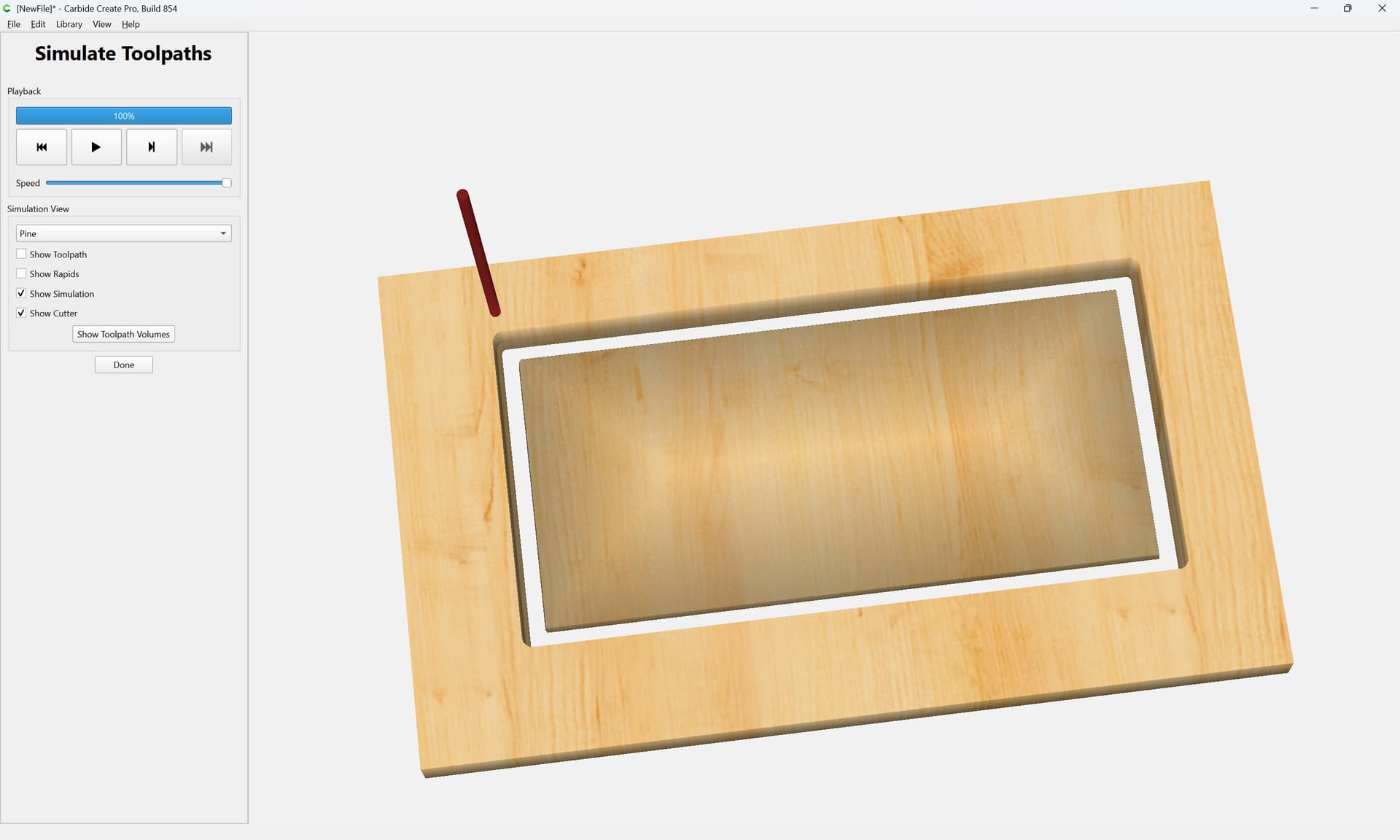
If you still have difficulty with this, I’d suggest signing up for a training session.
2 Likes
If your boundary curve is right on the edge, the tool stops here…
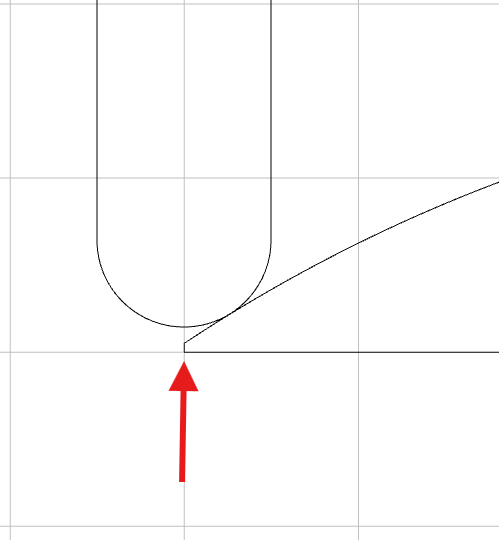
Move the boundary outward, and it will reach the actual corner or if further roll around the corner.
3 Likes
Scale your geometry within the Model tab to just outside of the offset geometry.
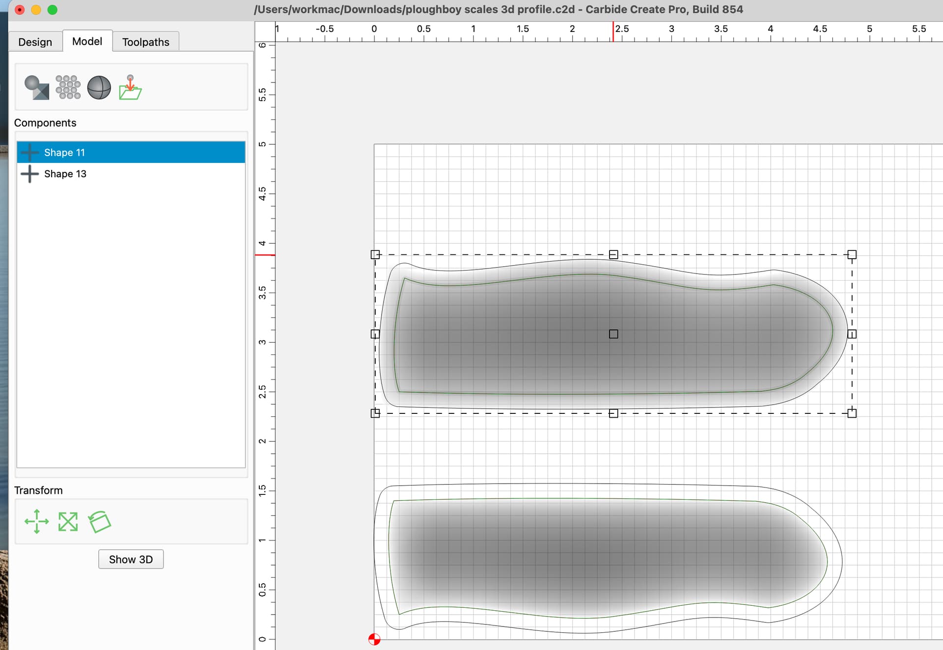
ploughboy scales 3d profile_b.c2d (960 KB)
3 Likes