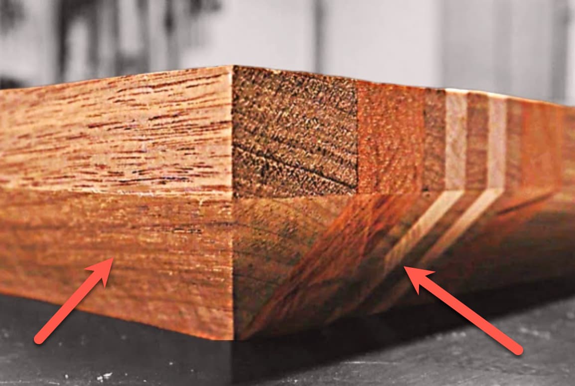
So I have a block of wood that I want to create a sloped plane on. Unfortunately, that’s the best way I can describe it. Like a large chamfer.
Not unlike the image below which I am using to try to demonstrate the slope/angle concept.
I don’t know what words to search for on this. Is that a kind of contour? Are there any tutorials, documentation or you tube video that can get me pointed in the right direction? For whatever reason, I’m struggling with how to do it and how to look for something helpful.
model in 3D in Carbide Create Pro — requires a much larger stock area than area of the largest axis to be sloped
draw in greyscale and import as a height/depth map into Carbide Create Pro
draw a series of vectors and assign toolpaths to the necessary depths (this works best if one has a V tool with a matching angle, otherwise it’s ball-nose and scallops and sanding)
model in some programmatic tool and create G-code to send to the machine
Some possibly helpful threads:
If you’ll upload a dimensioned .c2d file we can walk through whichever technique suits
Really depends on what kind of a slope you’re looking to make. A long wedge-like shape or a short chamfer-style. A short chamfer-style can be most easily accomplished with an appropriate V-bit & easily setup & simulated in CC.
A longer wedge-style slope can be modeled in CC Pro, but it takes a fair bit of design acrobatics depending what the objective is. Modelling in third party CAD can be easier after which an STL of the object can then be imported to CC Pro for toolpaths generation. Either method requires 3D Finish toolpaths to rasterize the cutting tool across with a stepover small enough to make tooling marks negligible.