does anyone have any info or references on how to draw a design and convert it to be cut?
Pretty broad subject. Carbide create has a few drawing tools, but you can also make vectors in other drawing programs and import those vectors (.svg files) into carbide create. We have quite an extensive collection of videos done by Kevin that cover a lot of info both on our youtube channel and my.carbide3d.com
Is there something specific you are having issues with?
1 Like
As @Radiation said that is a big subject. Give some details about what you want to do. If you can find art work on the internet you can use the free Inkscape to convert the image to an svg. You can buy some images on etsy.com but sometimes they are rather sloppily done and you have to clean them up.
The easiest way is to draw your design in CC and import any svg images into the design.
Two videos which show creating a design in-depth:


and we’ve walked through various designs beginning to end:
What would you like to make and how would you like to approach it?
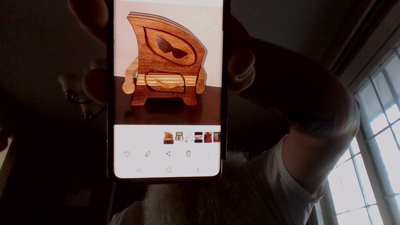
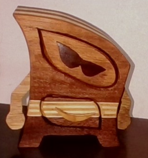
HERES WHAT I WOULD LIKE TO TRY THEY ARE CALLED BANDSAW BOXES, BANDSAW…BUT IM GUESSING A CNC WOULD BE ABLE TO MAKE THEM AS WELL
What do you wish to work from as an original? That photo?
Note that a CNC is quite different from a bandsaw, w/ a wider kerf, so it’s not possible to do tricks such as cut up a glue-up and then glue the entry-point together.
That said, we can work up a vector drawing of the design in question, and it could then be cut out in some suitable way — probably using 5 separate layers, and then inlay onto the front would be most straight-forward.
For a starting point see:
and it may help to review:
https://my.carbide3d.com/#Design_with_Carbide_Create
and also see:
and
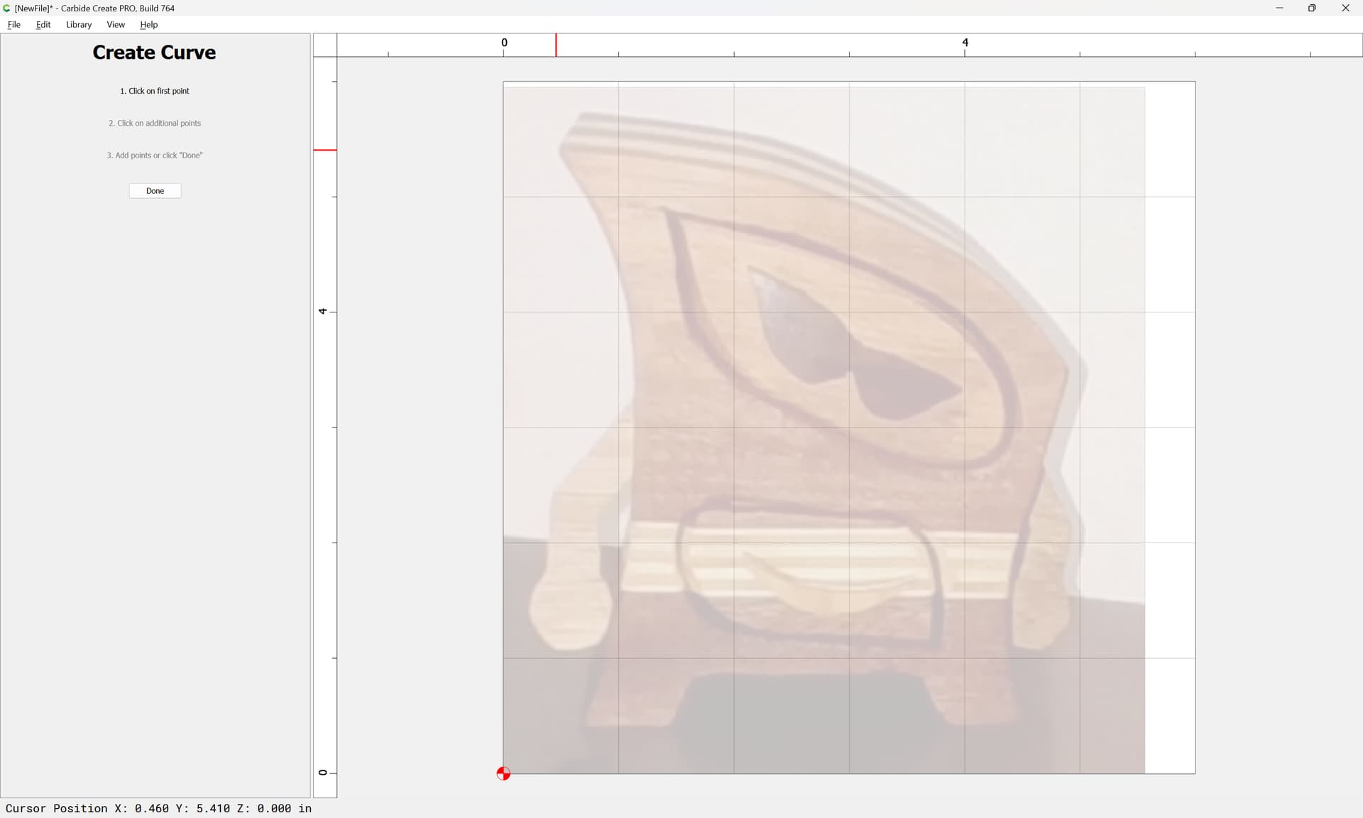
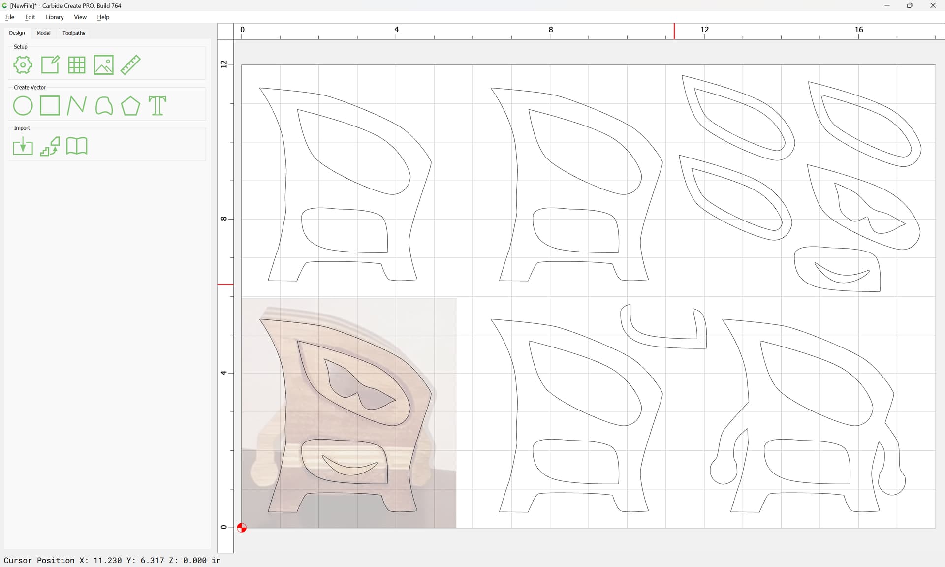
First, get the image:
Then, import it into Carbide Create as a background:
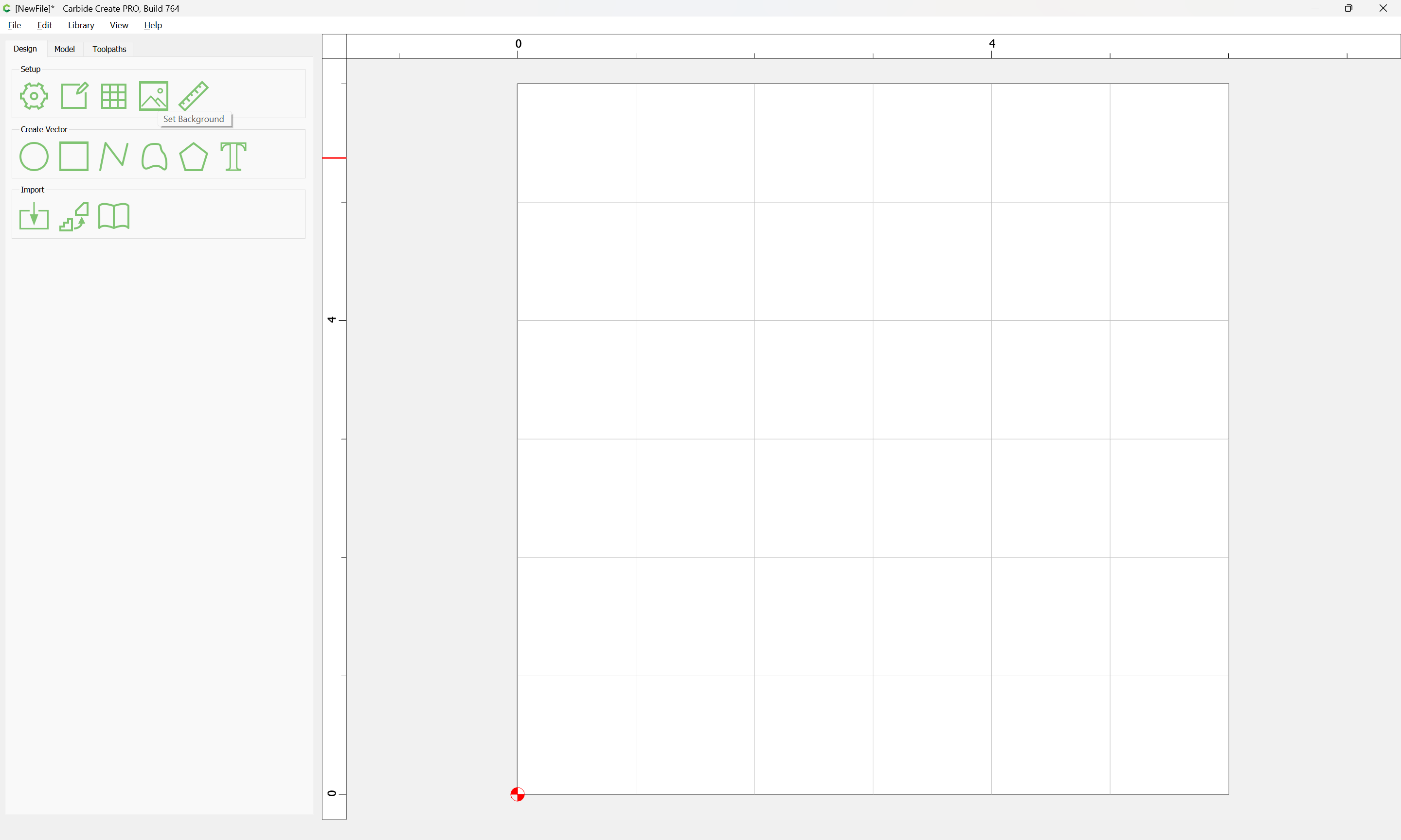
Set Background

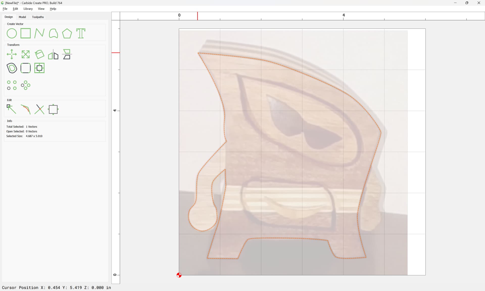
Then draw.
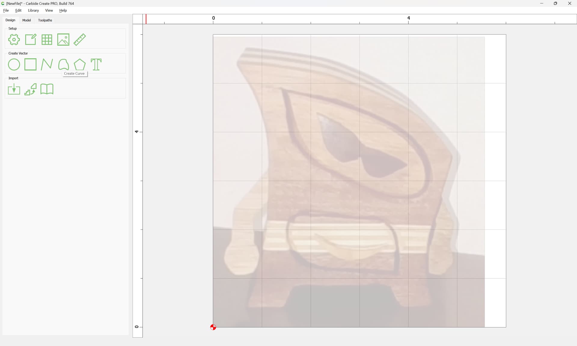


Click to close the path and exit drawing:
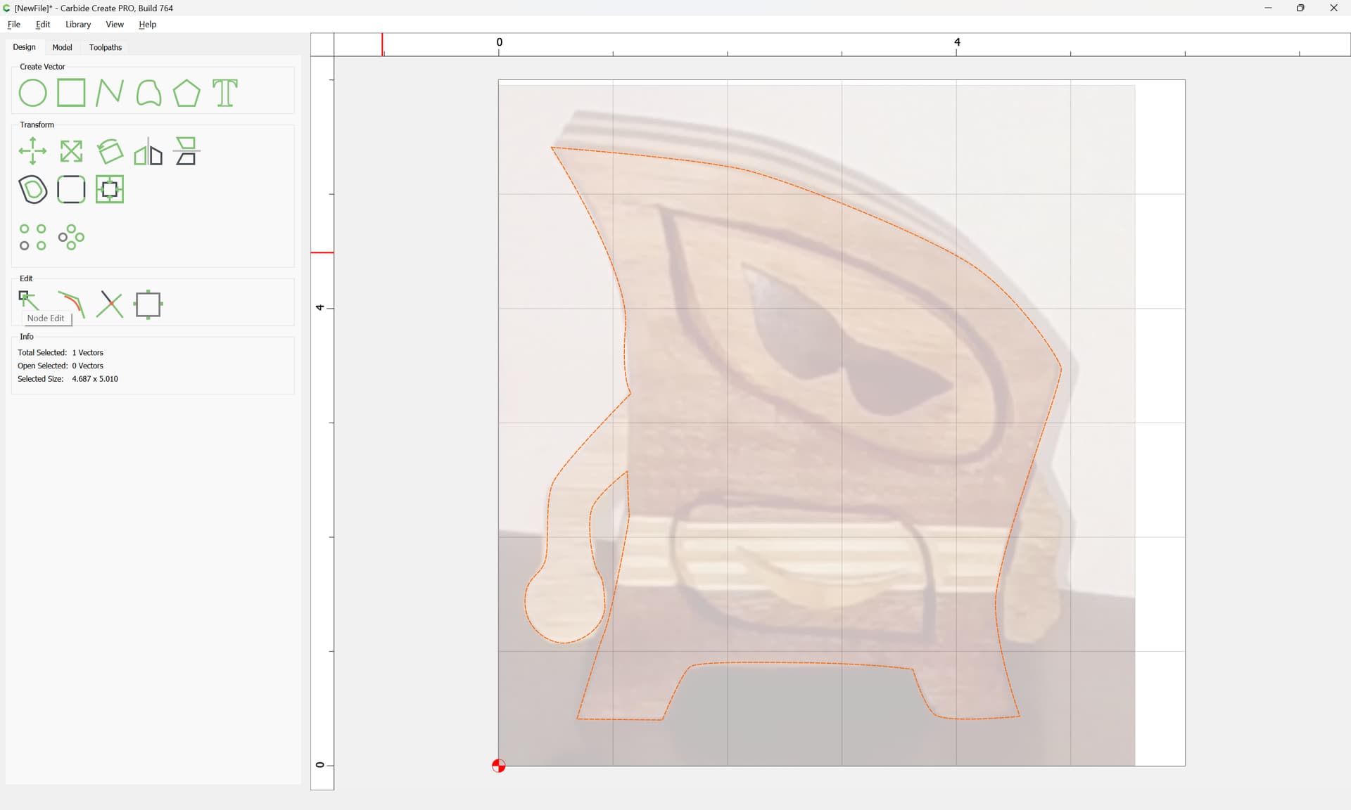
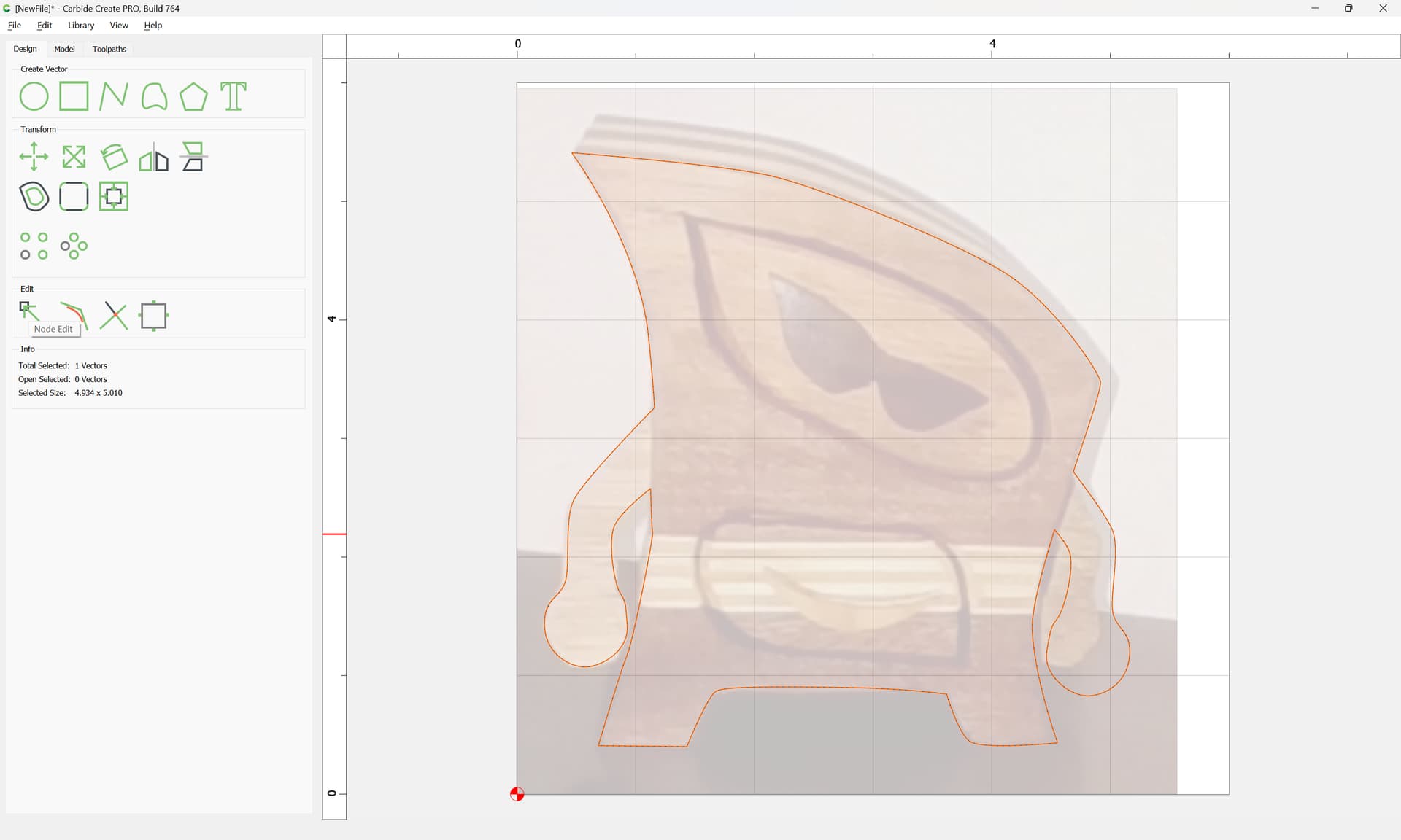
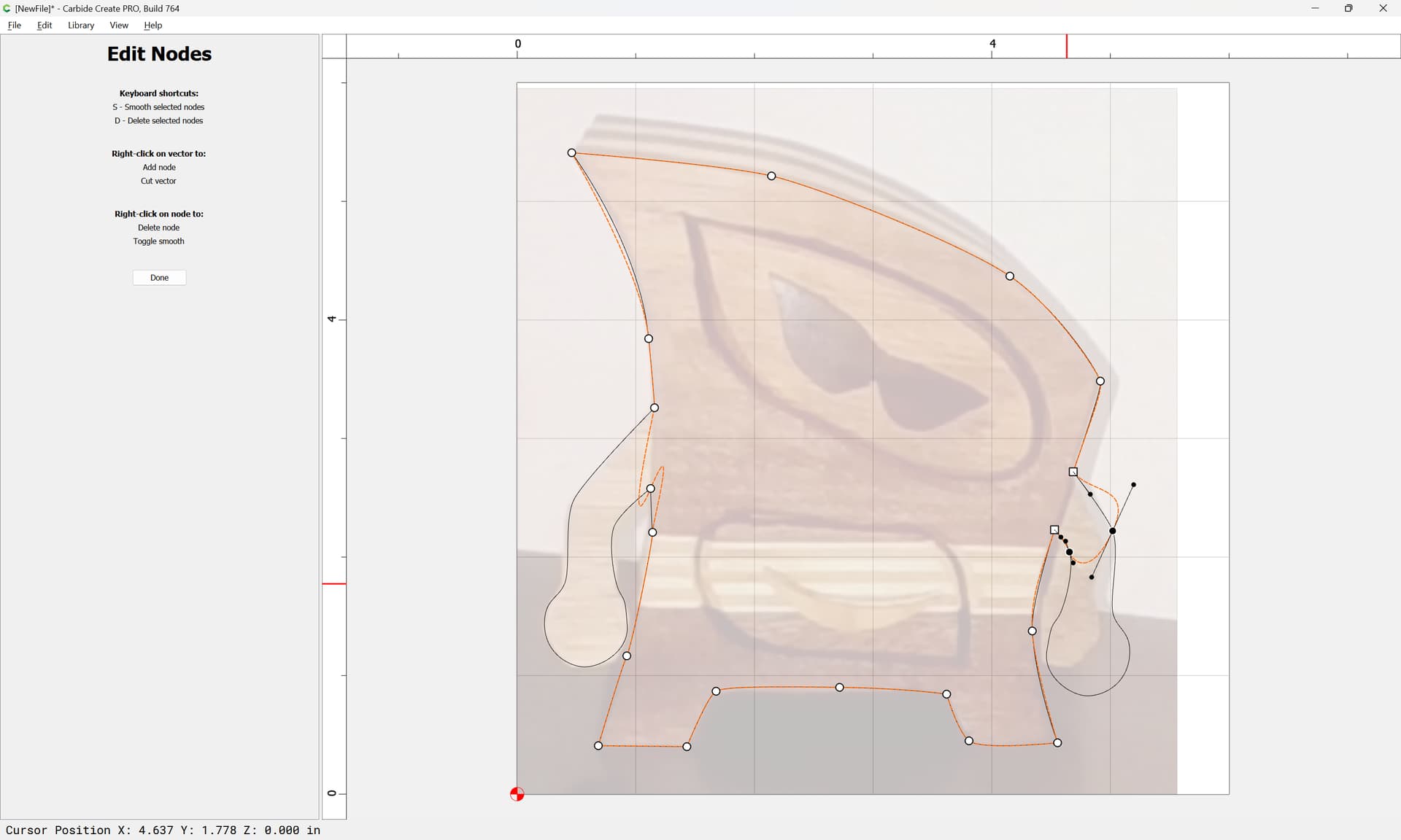
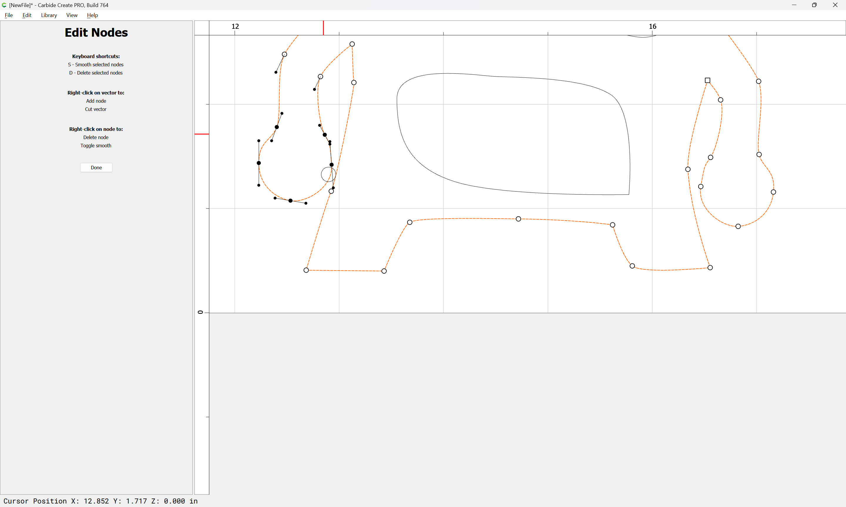
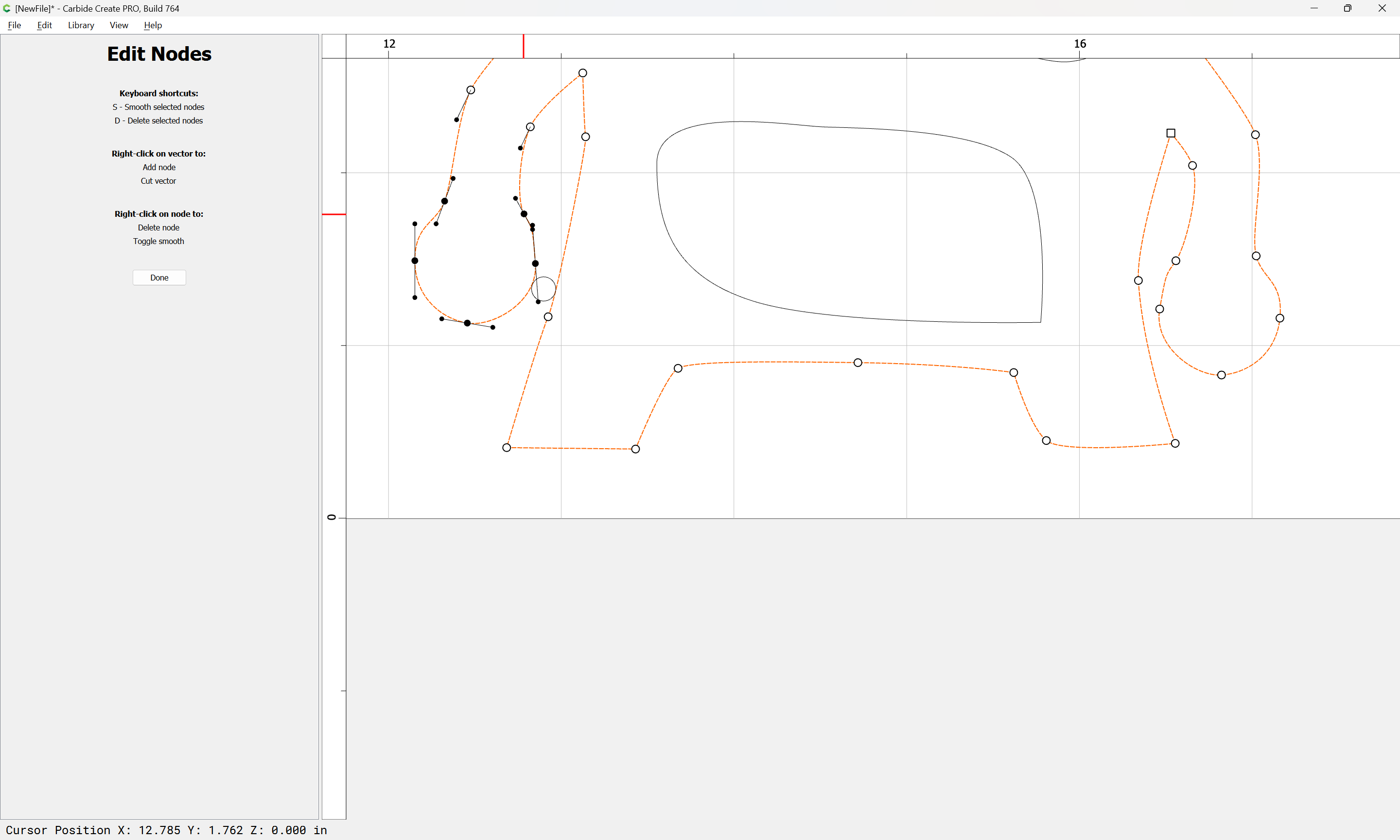
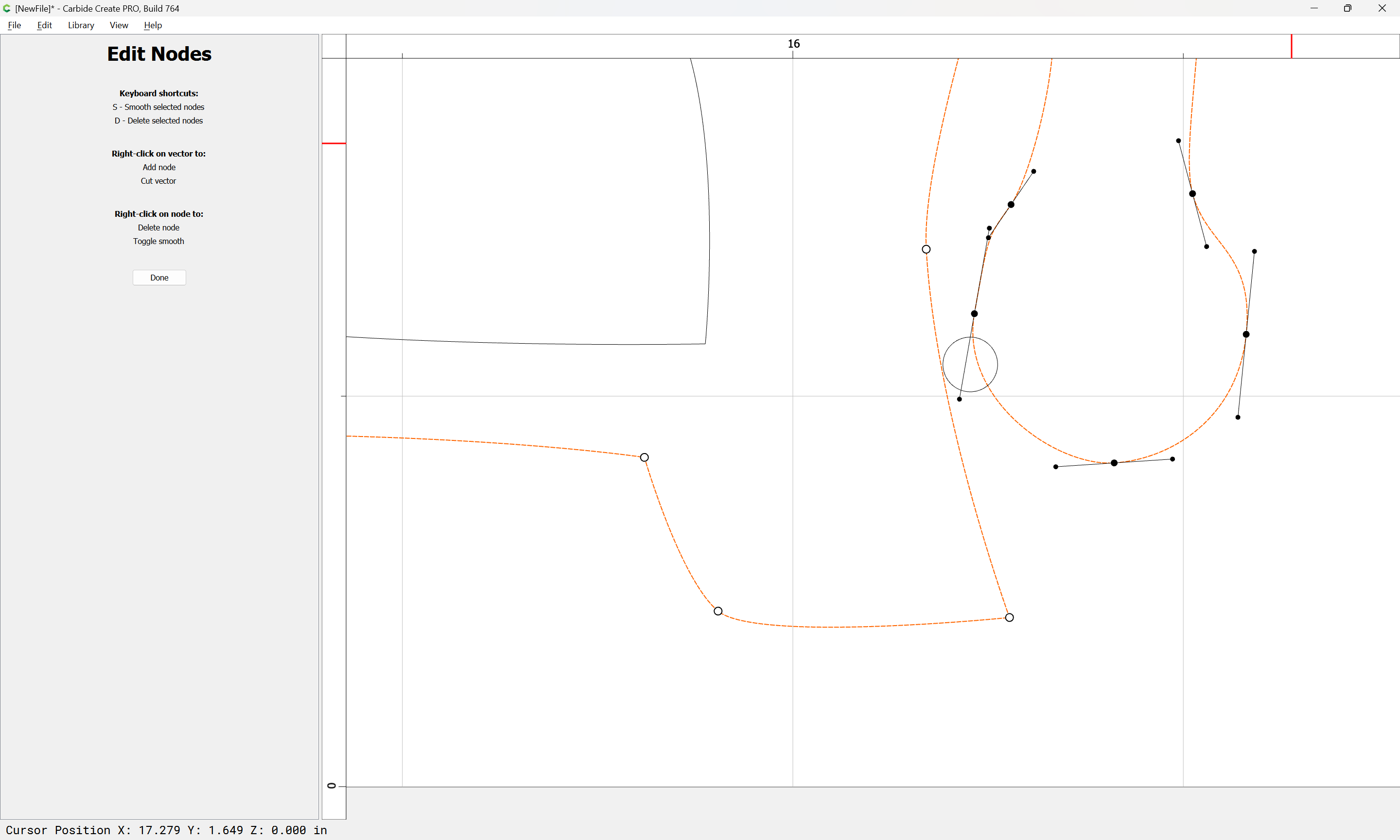
Turn off Snap to Grid if need be and go into Node Editing and clean up as necessary:

and adjust things as desired:

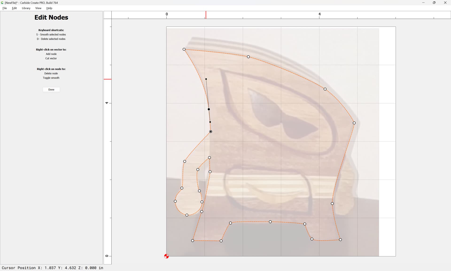
Done
Note that it will be necessary to draw in the missing arm — we’ll do that by mirroring the first:
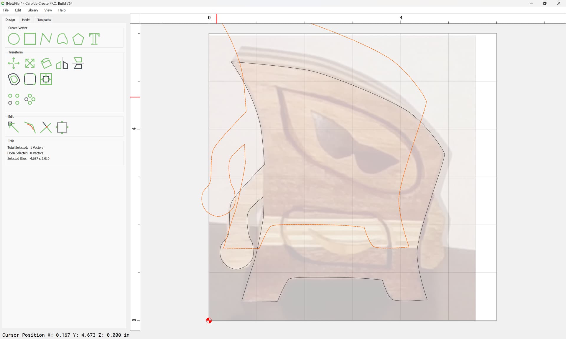

Positioning it:
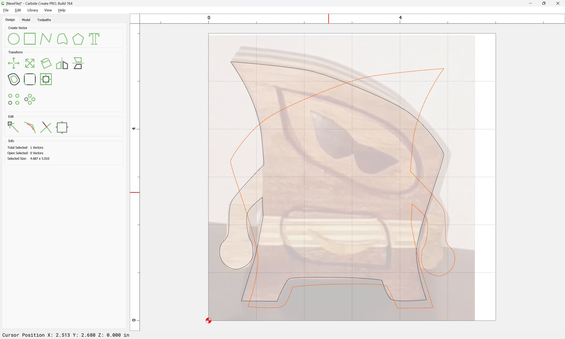
and rotating a bit:
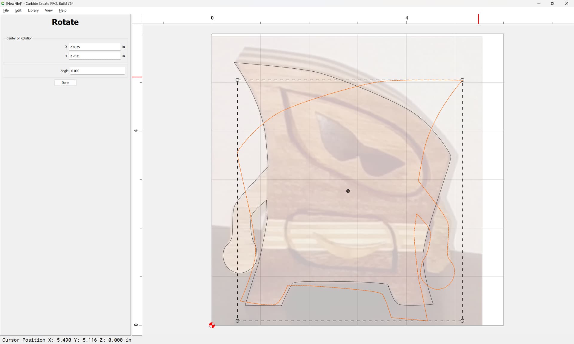
Done

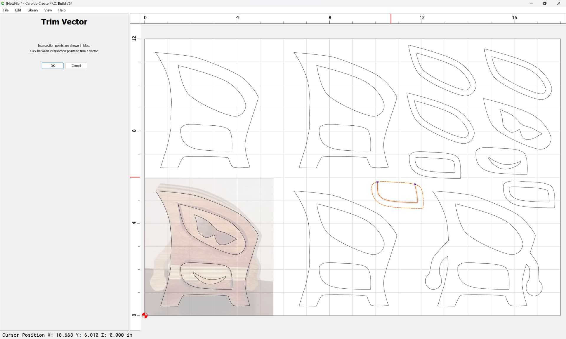
Select both:
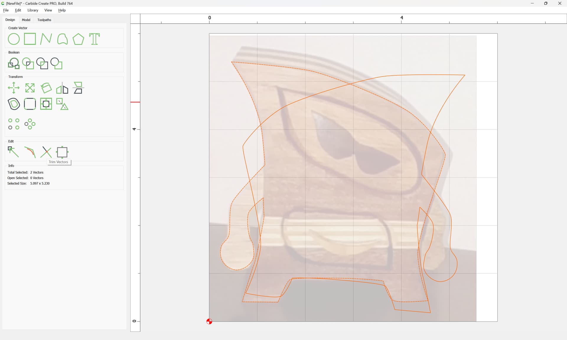
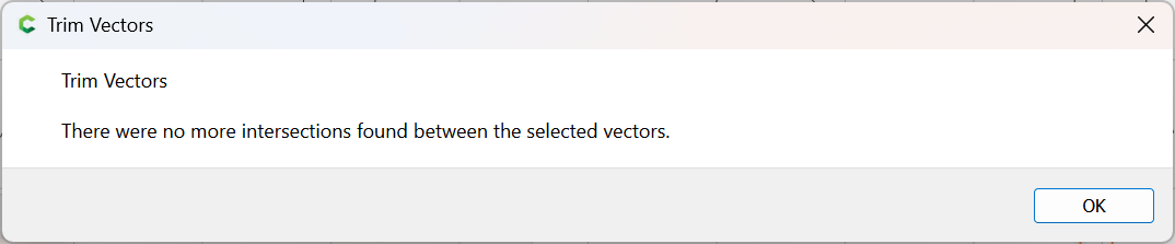
and use “Trim Vectors” to remove what is not wanted:


Once we have opened up the original and isolated the section which we wish to keep:
OK
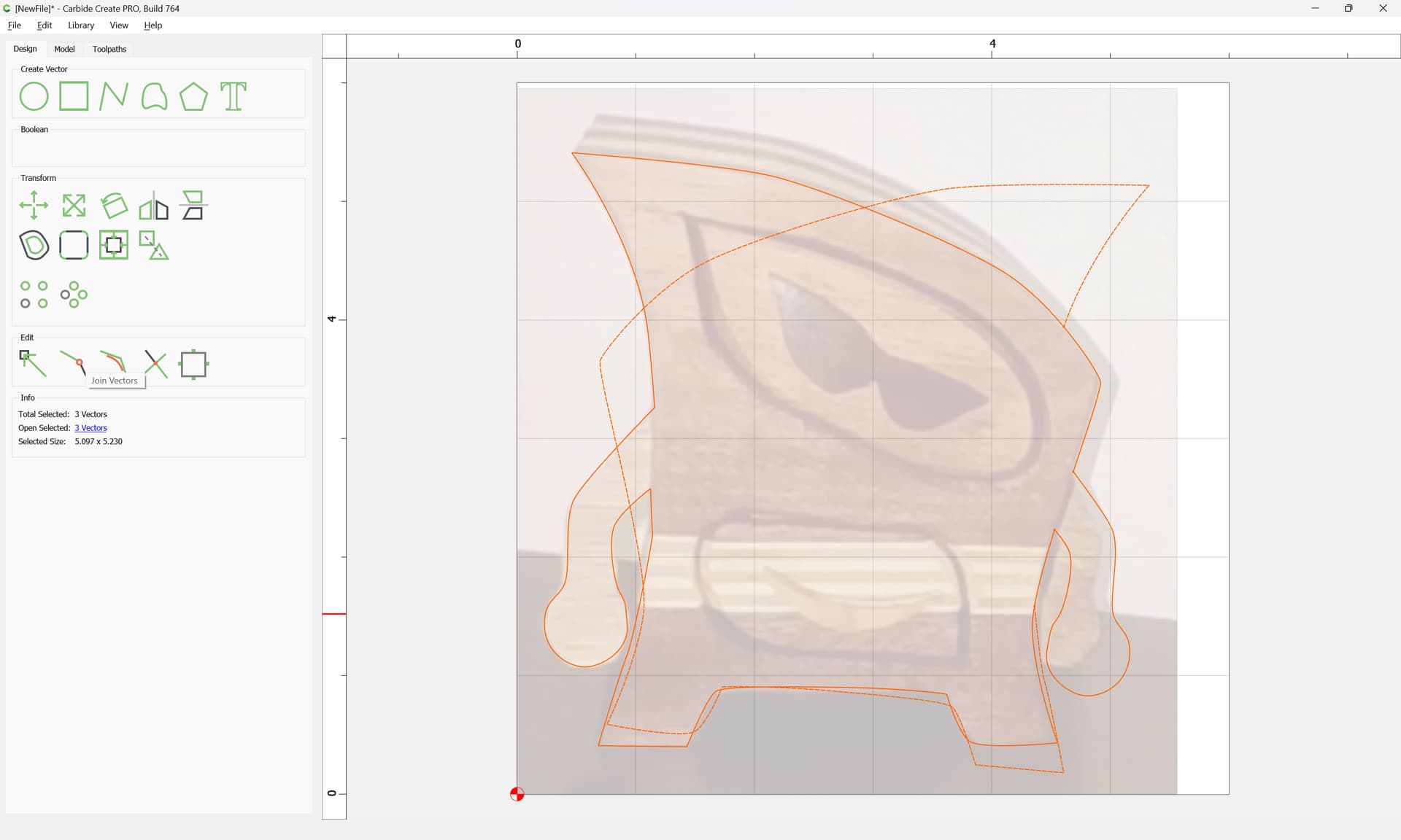
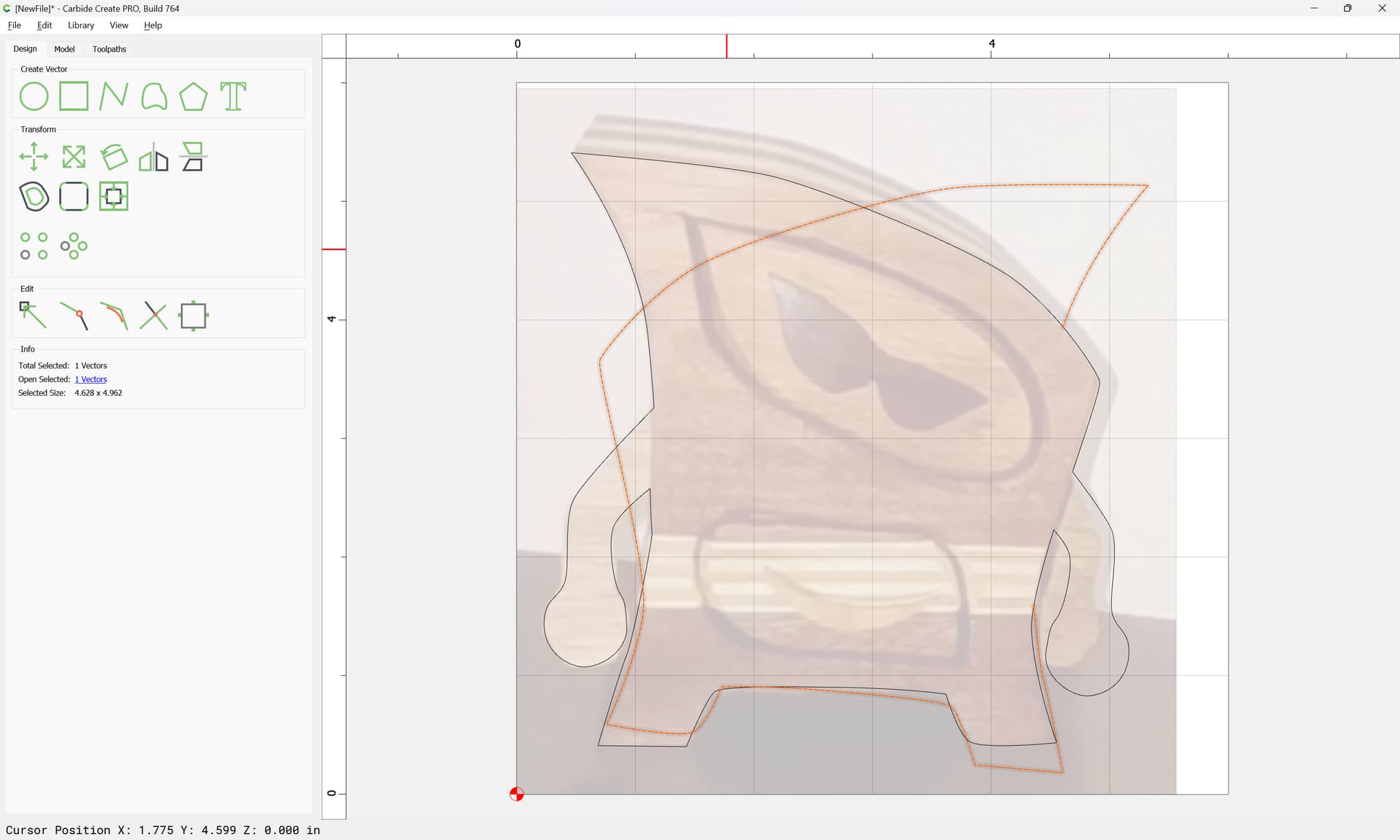
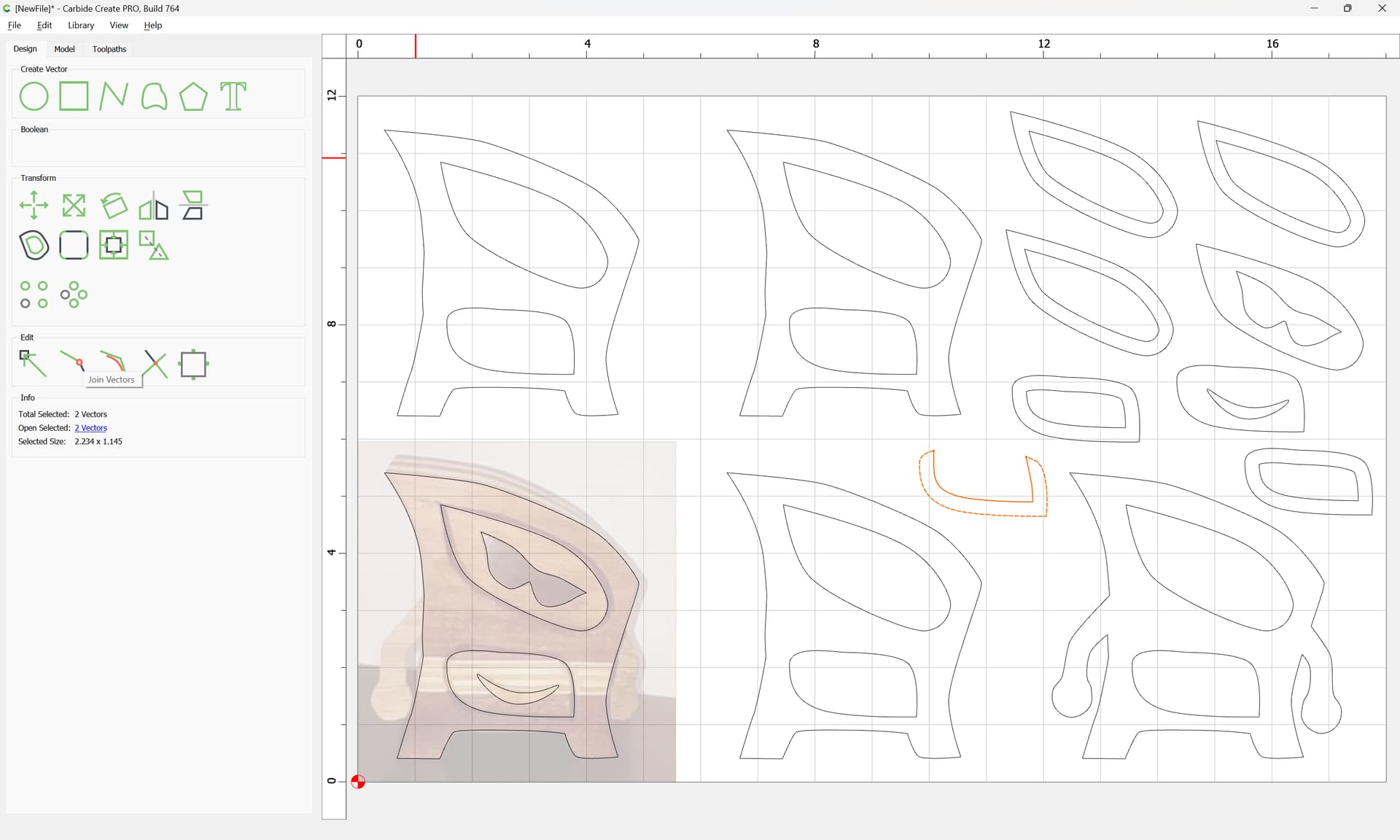
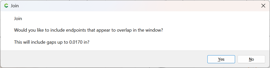
Use “Join Vectors” to join together the outline:
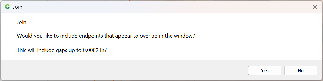
Yes
click away to de-select:

Select the unwanted geometry:
delete it:

Then copy-paste the design in place:

and Node Edit one to remove the arms:


delete what is not wanted:

and repeat as needed:


Adjust so that things line up as desired:

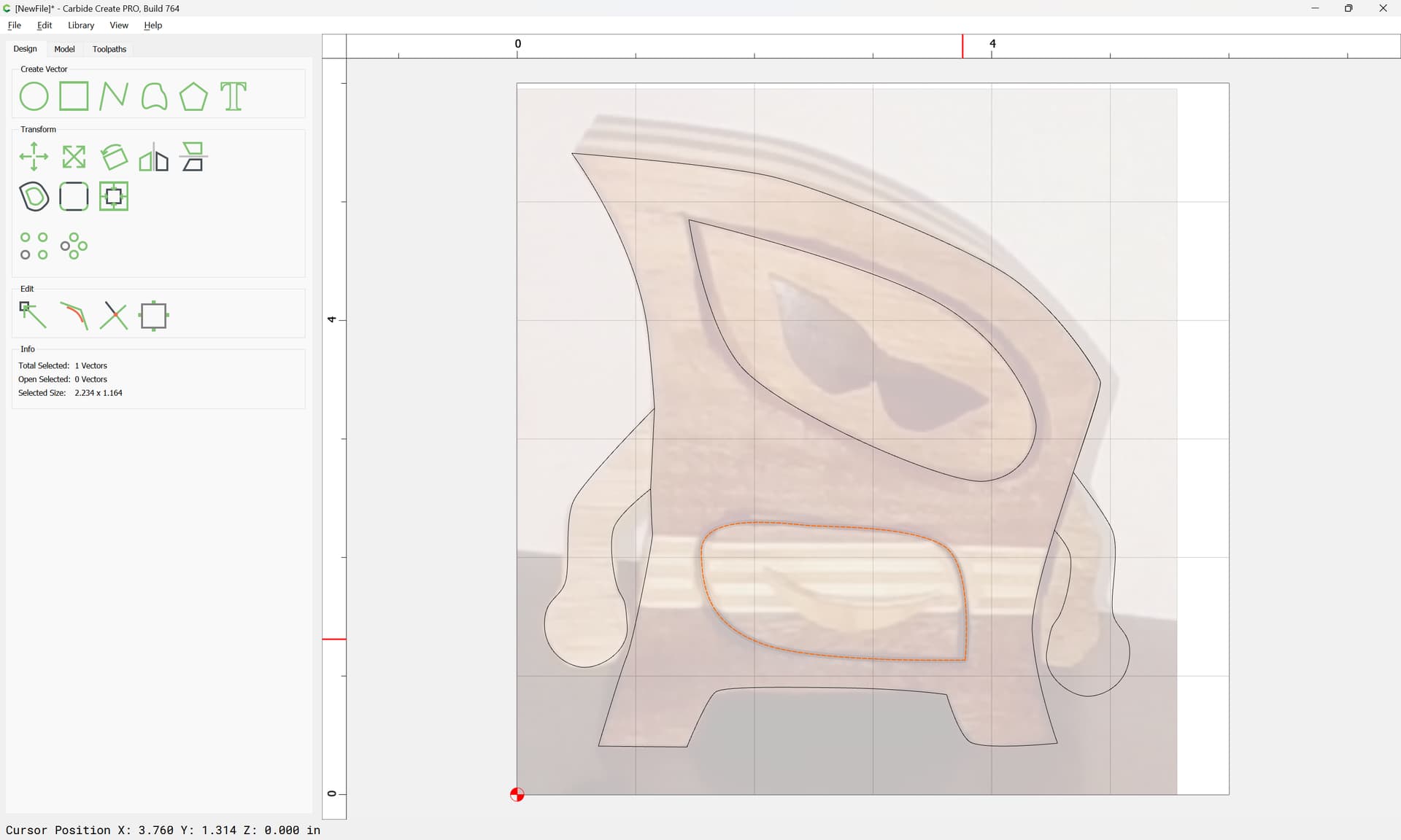
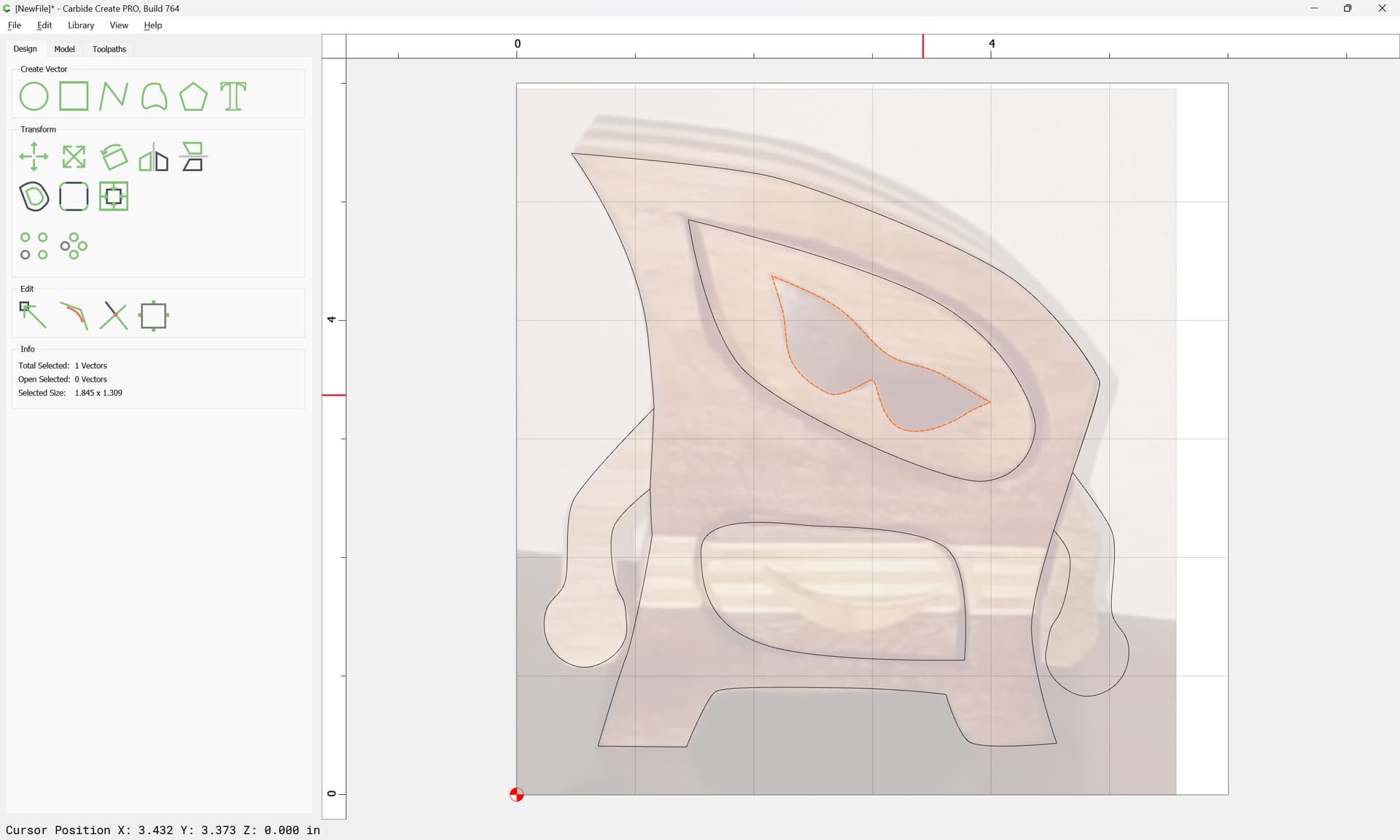
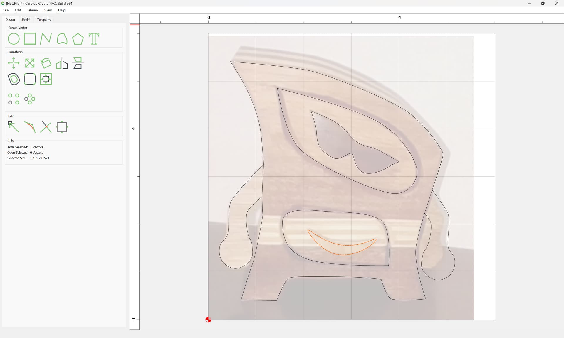
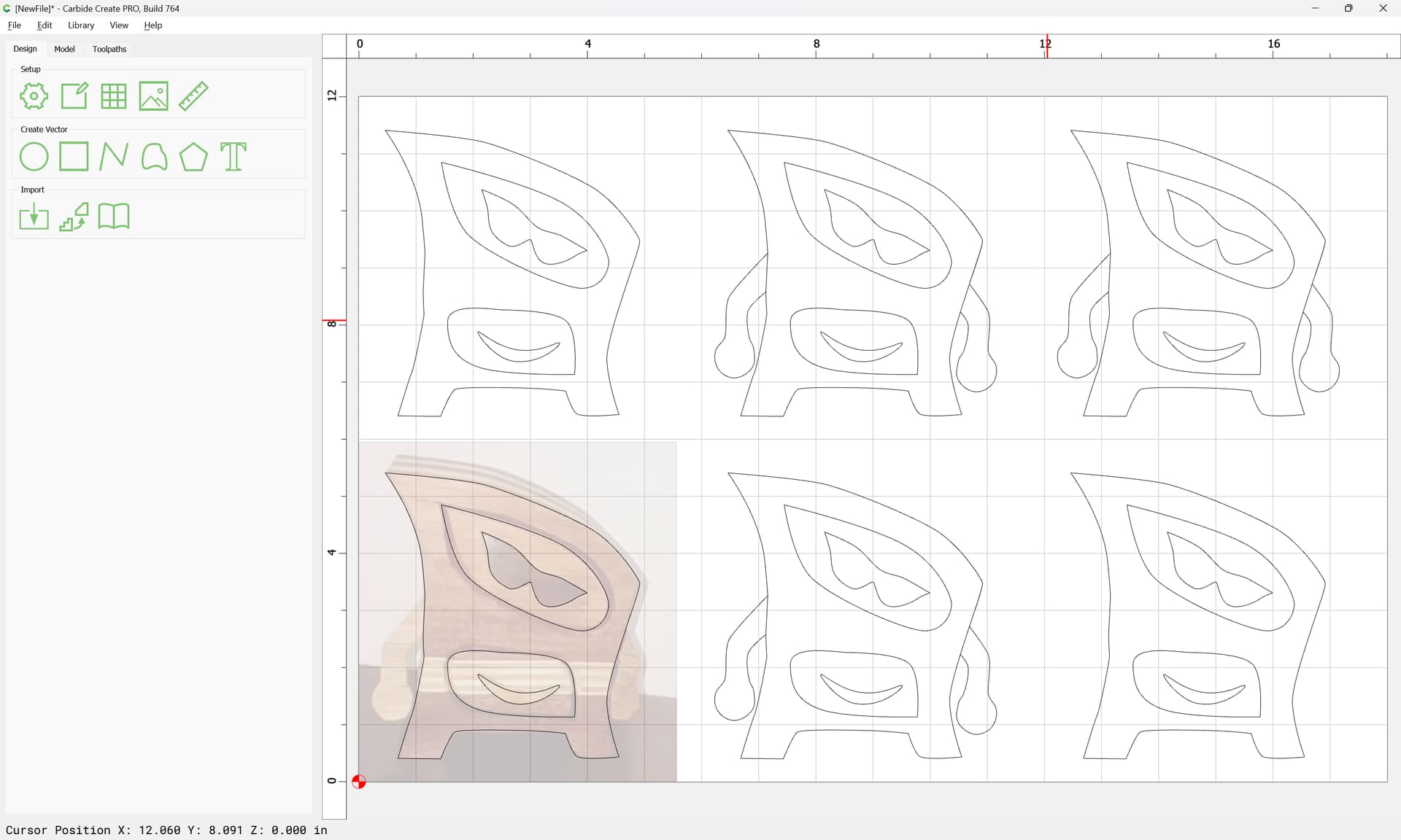
Draw in the remaining elements:

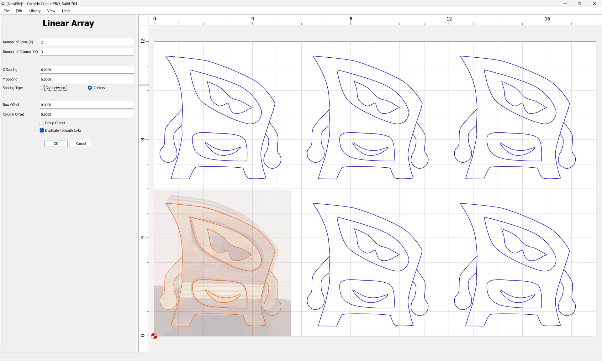
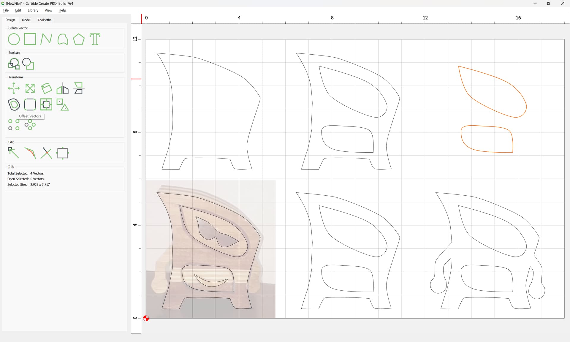
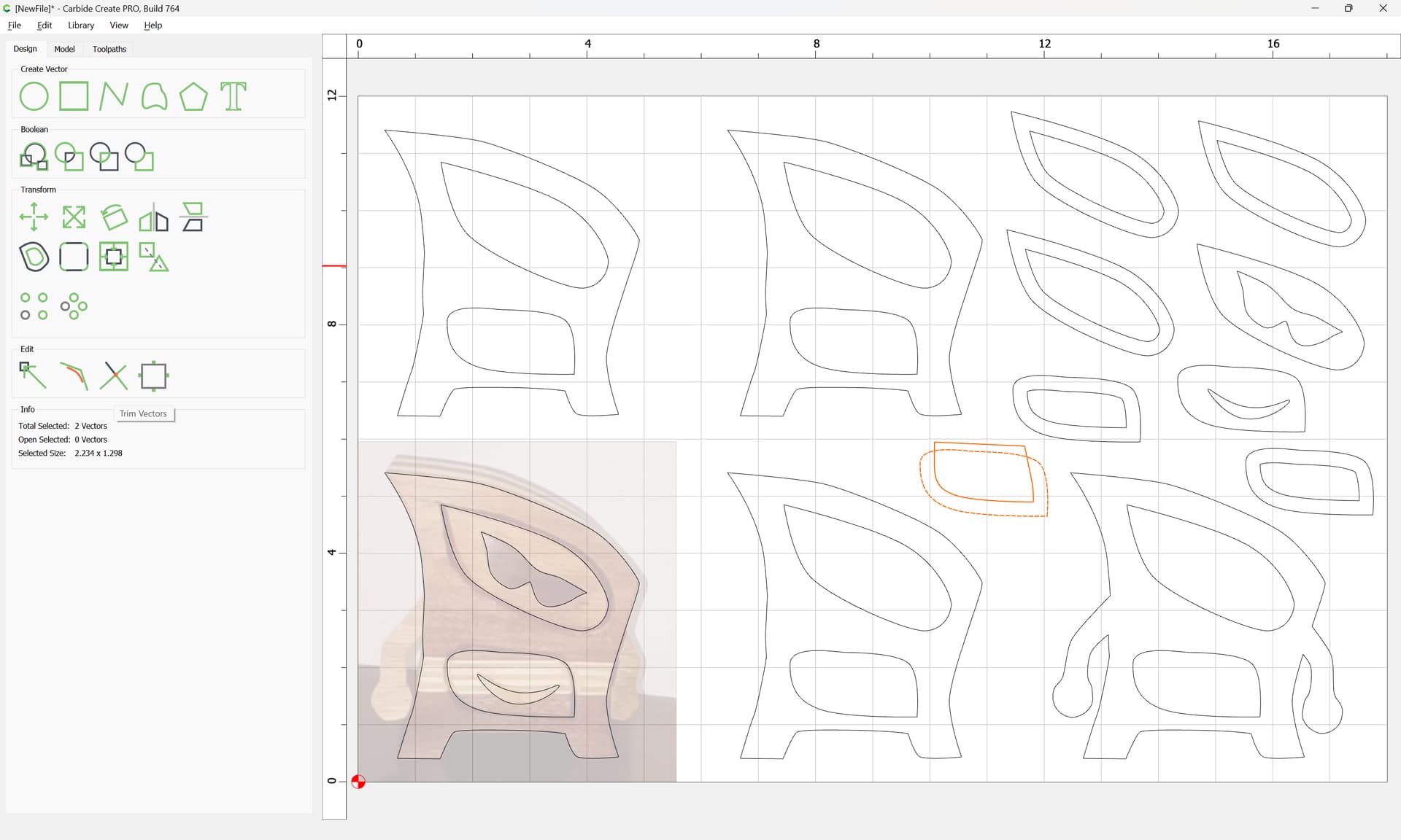
Duplicate things 5 or 6 times to create the geometry to which toolpaths will be assigned:
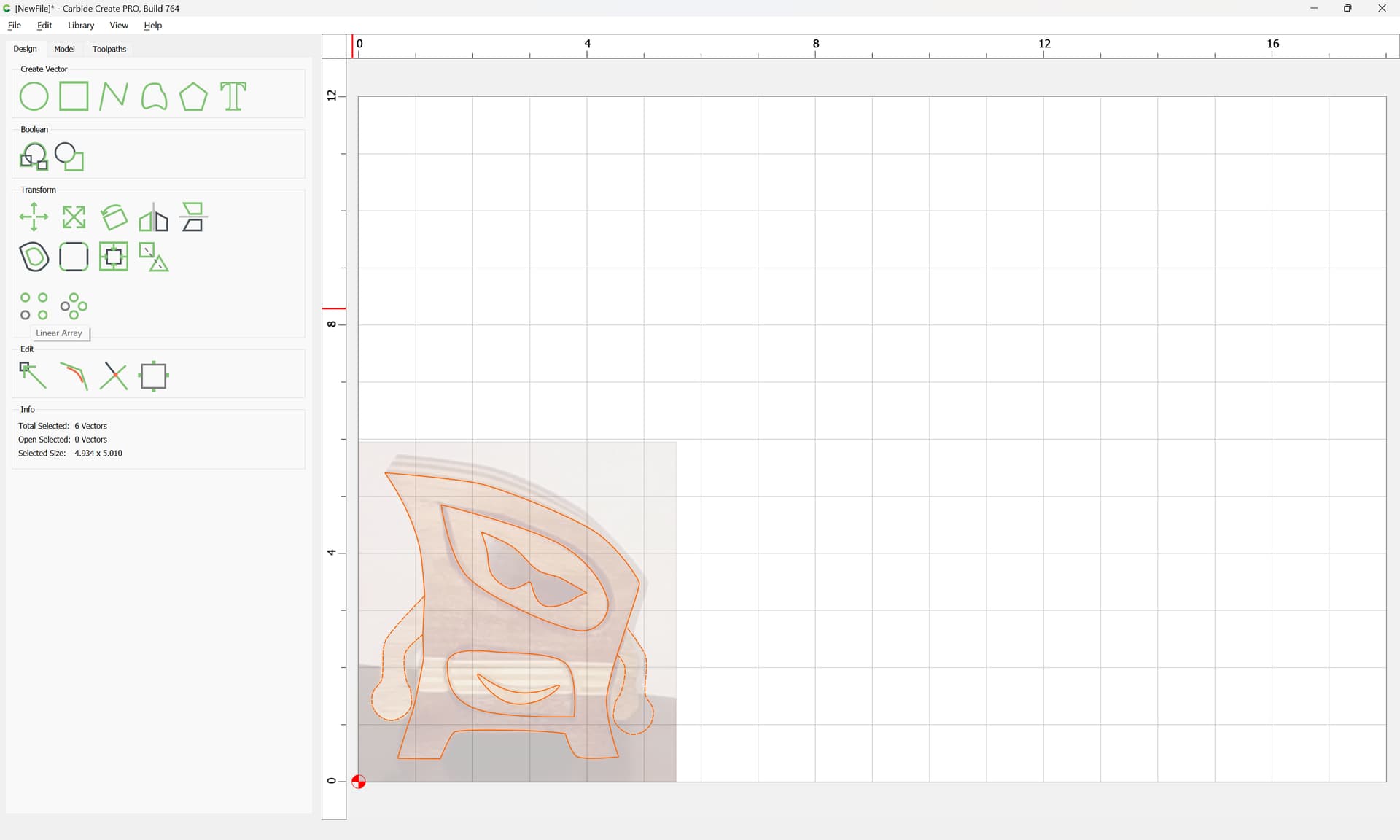
Linear Array is one approach:
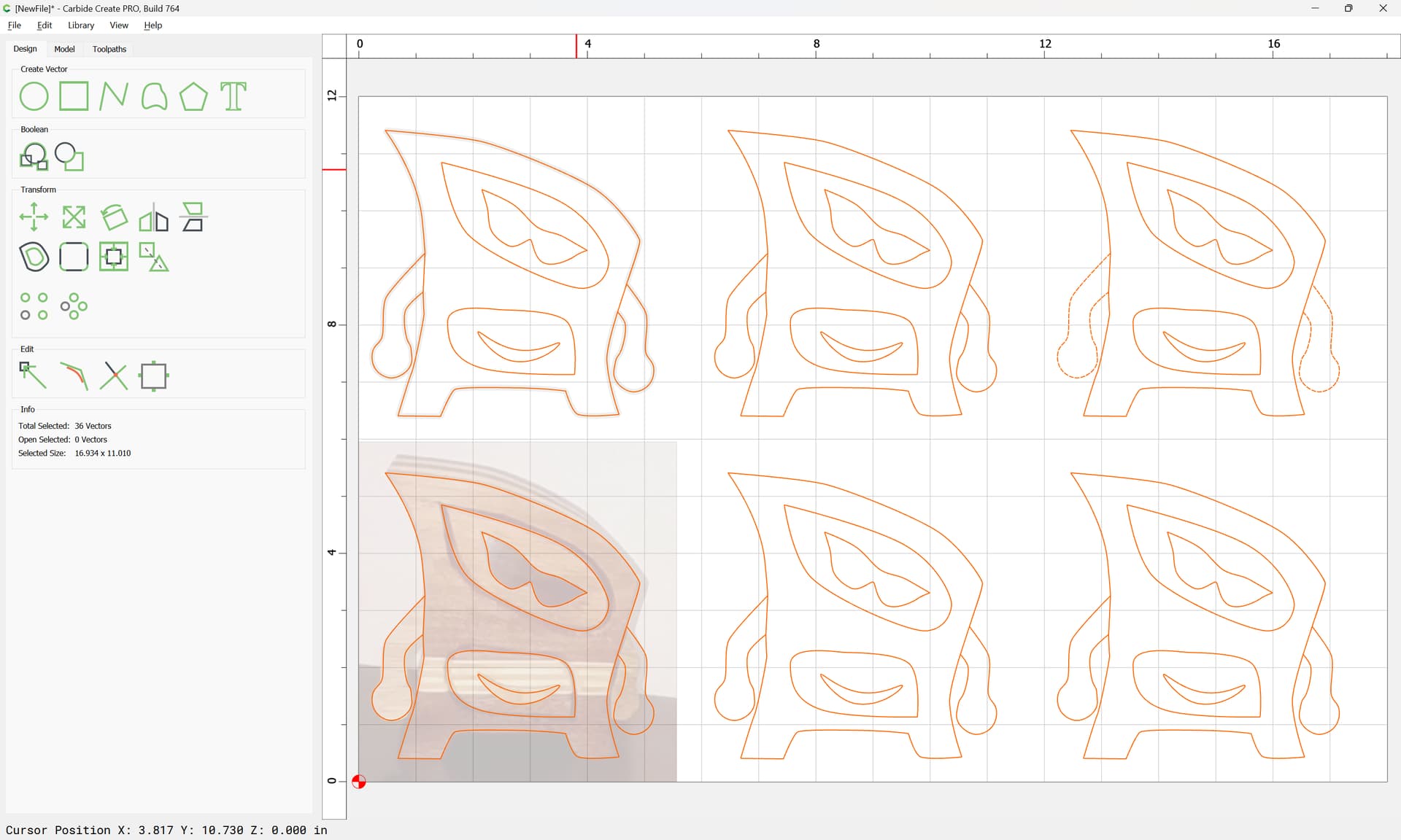
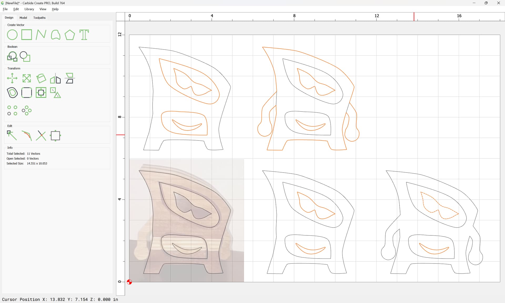
Delete the arms from the versions which don’t need them:
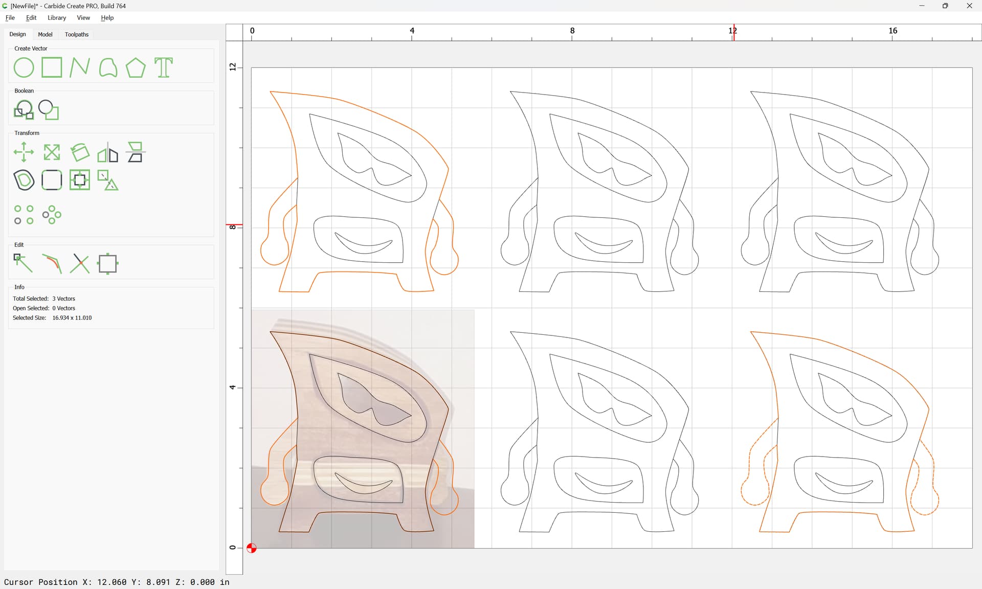
Delete the interior outline from the version which doesn’t need it:
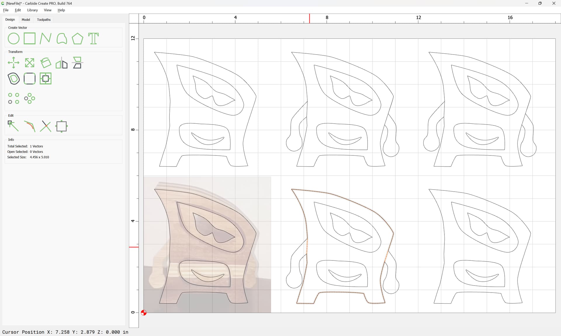
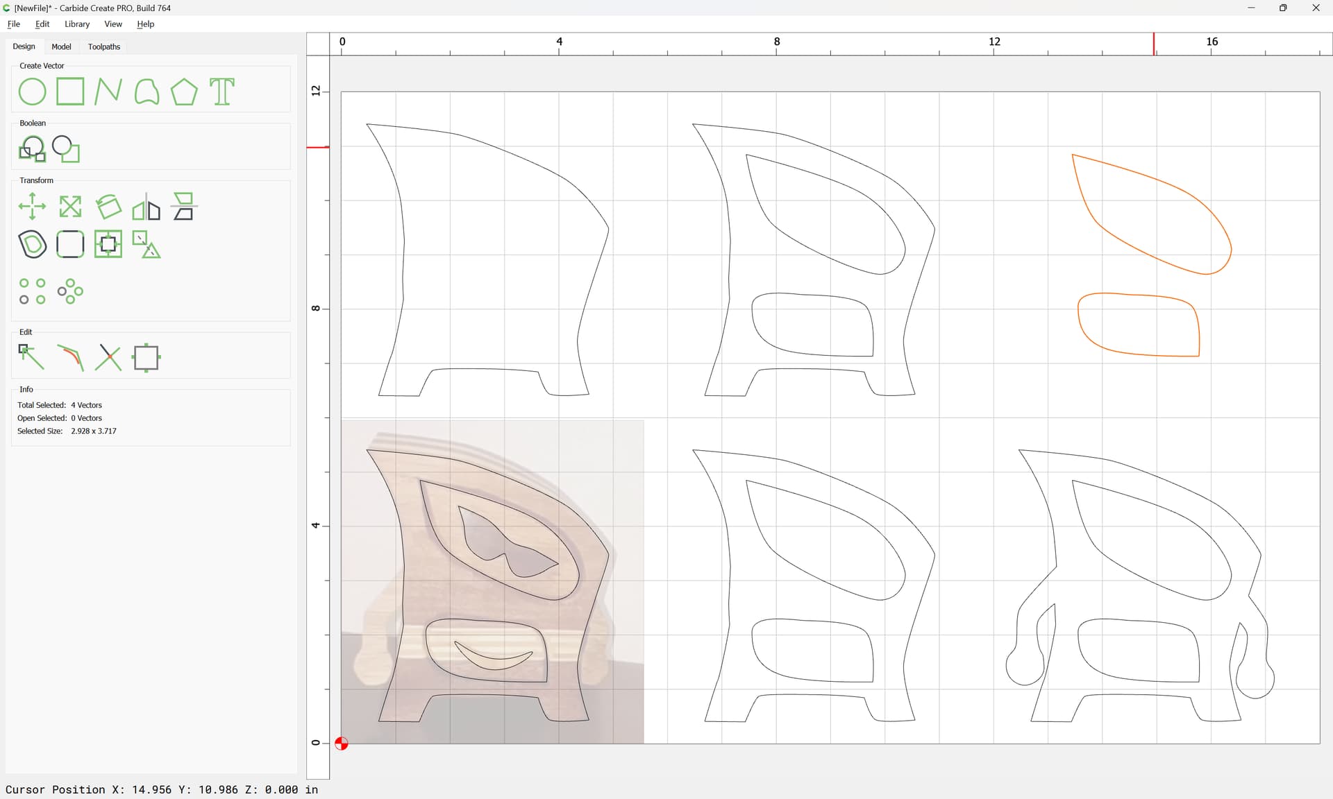
Delete elements which won’t be needed:
and if need be re-arrange:

Assign toolpaths
what id like to do is clue up the proper thickness then cut out like you would a bowl that parts easy its making diffrent designs and importing them im needing to learn
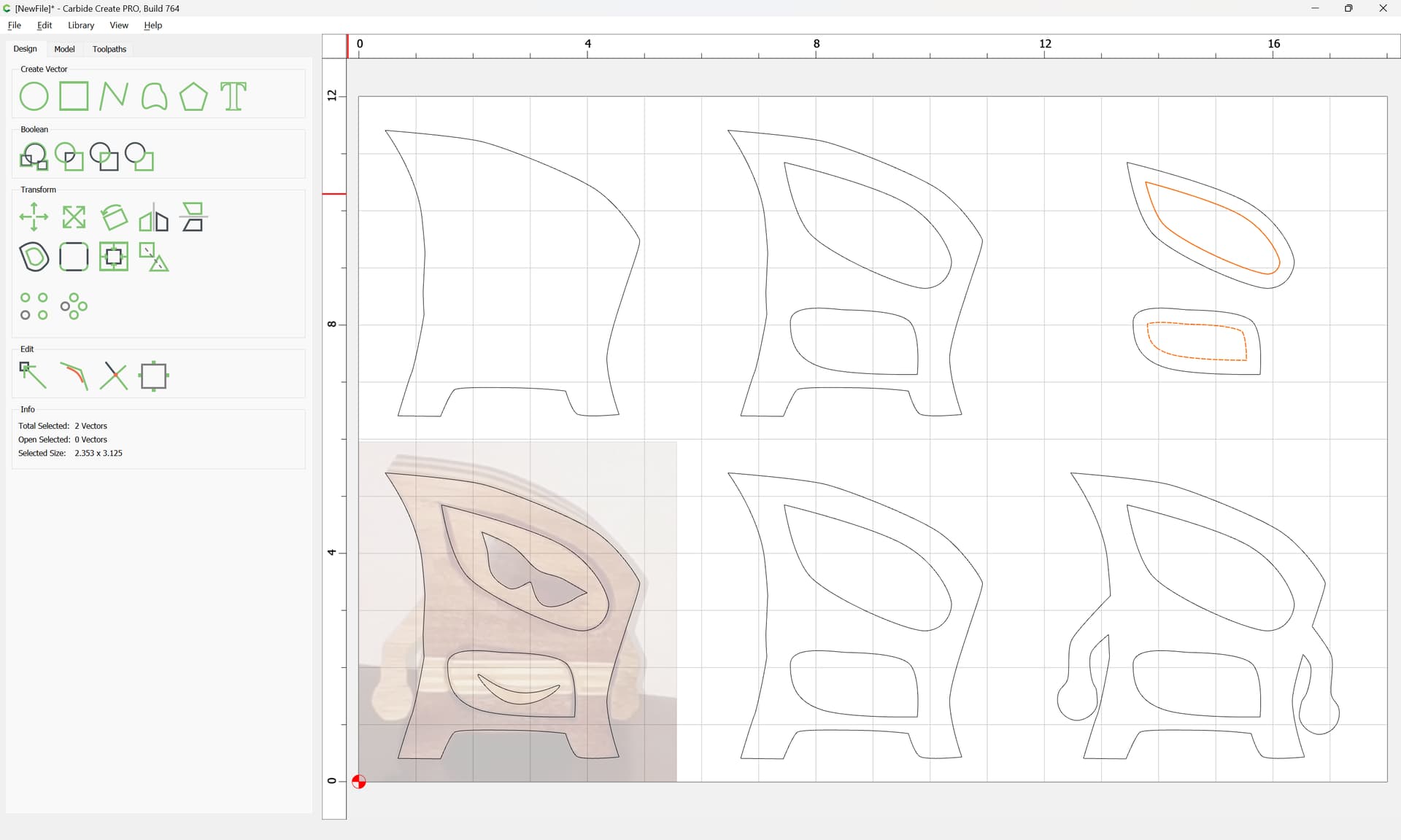
If need be, restore elements which were wrongly deleted — it will be necessary to have the drawer outlines so as to have drawers:
and they will need to be inset by a reasonable thickness:
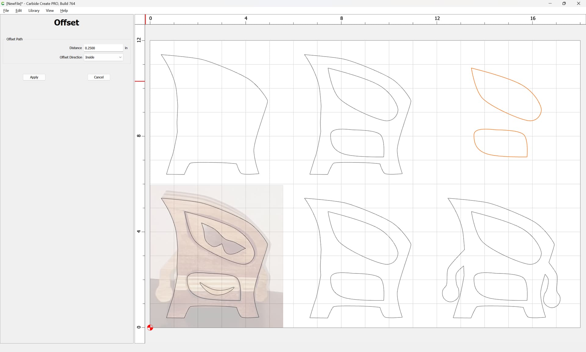
Apply
At this point, toolpaths may be set up to cut everything out — we will assume 1/4" thick stock — except that raises an important point about the arms — the need to be free of the body by endmill diameter + 10% — a quick edit:
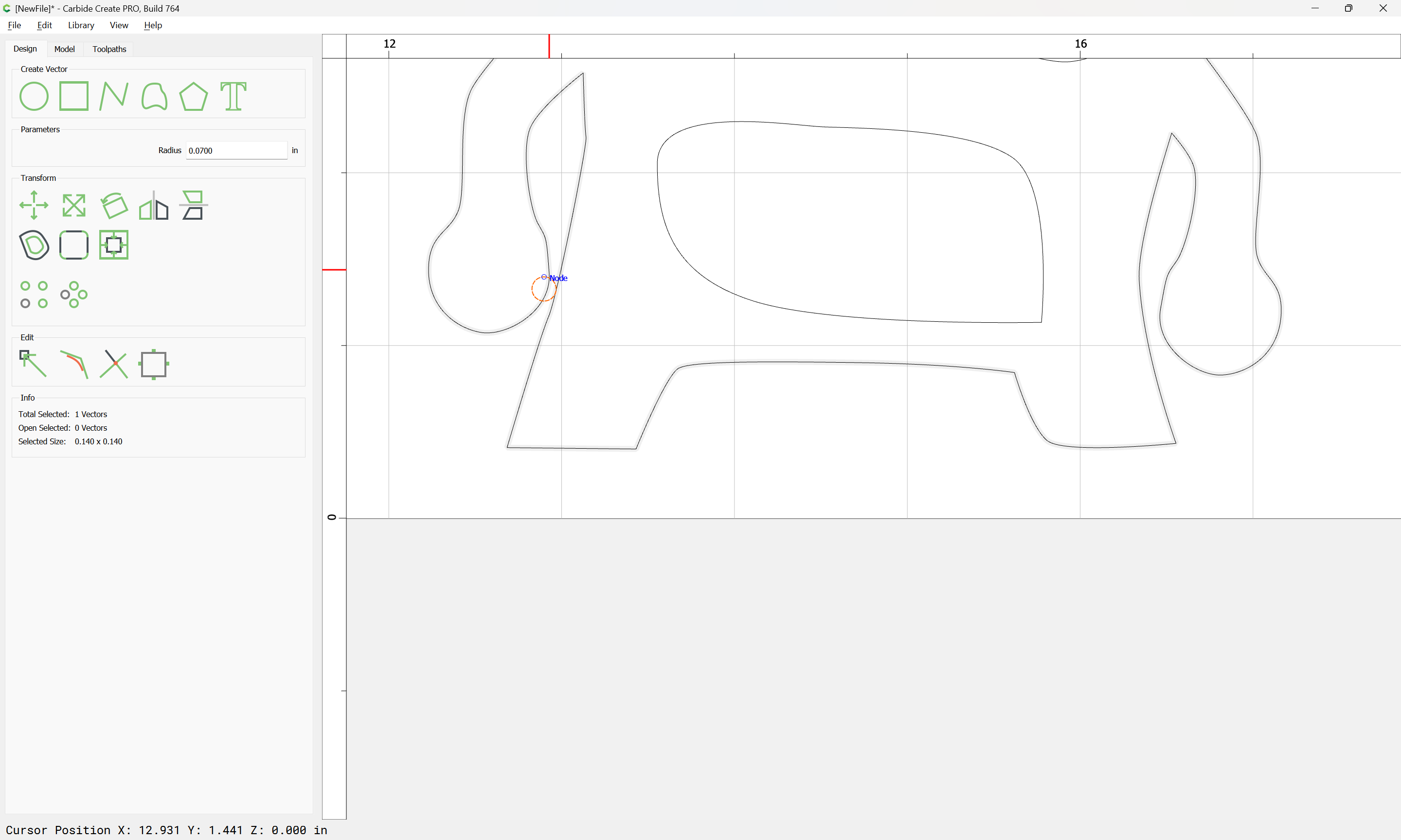
(we will necessarily use a 1/8" endmill)


An optional improvement would have been to add holes for alignment pins/dowels — doing so is left as an exercise for the user.
A further consideration is such boxes don’t have backs, and we will need openings for the drawers at the top:
OK

OK
Join Vectors:
Yes
Repeat for the other drawer

Cut parts out:
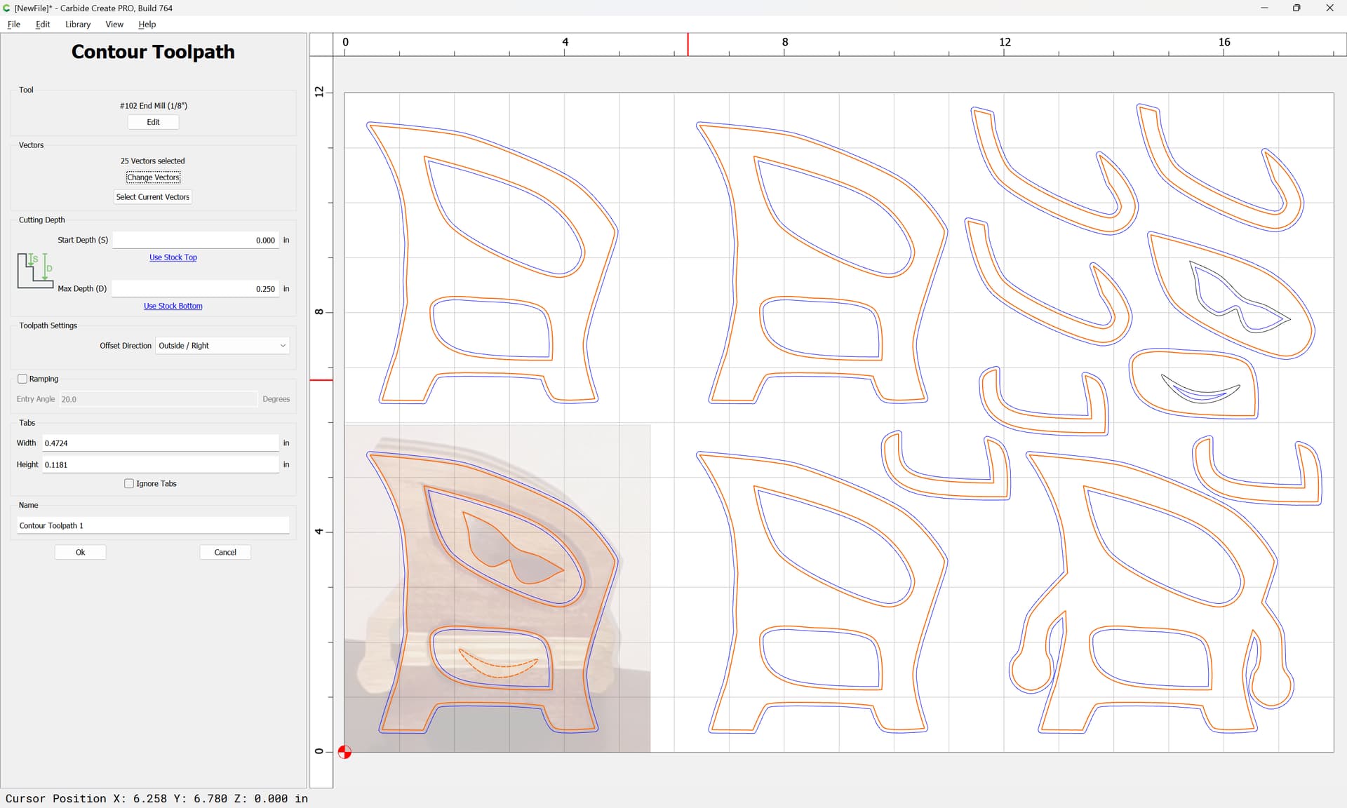
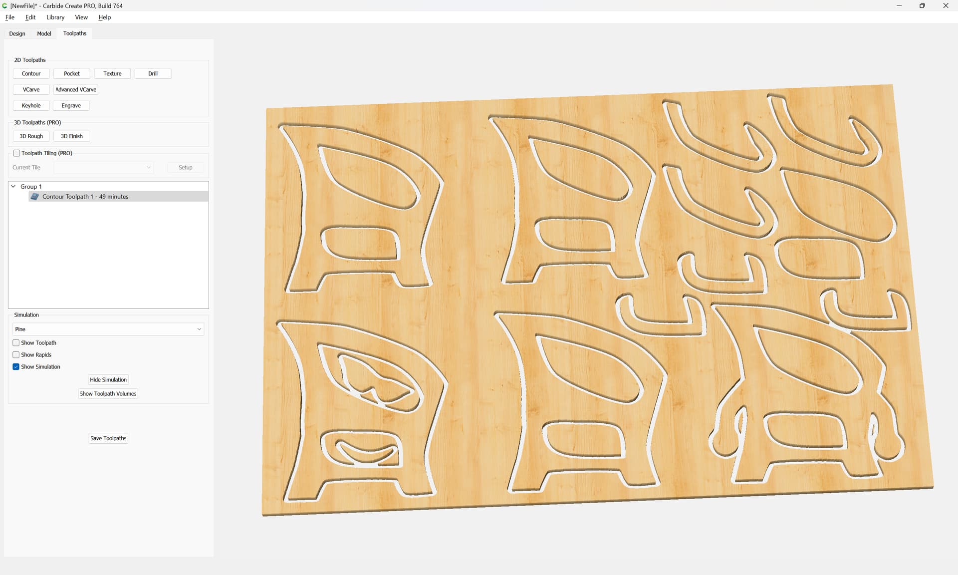
Adding tabs if need be, re-arranging for efficient use of material, and adding offsets to cut as a pocket down to tab height or the penultimate pass is left as an exercise for the reader.
Attached as a v7 file
outlinebox_v7.c2d (448 KB)
1 Like
If that doesn’t suit, an option would be to draw things up in dark outline, then scan them, then trace the scans:
this is awesome thanks WillAdams
1 Like
Our pleasure!
If you’ll let us know the specifics of anything else you are having difficulty with and we will do our best to work through things with you.
A big difference between a bandsaw box and cutting on the Shapeoko is the bandsaw kerf is much smaller than most of the bits that can cut deep enough to use the same block of wood. @WillAdams gives a good tutorial on how to create the images to cut out but you will notice that the kerf around the drawers is much larger than if cut on a bandsaw. So maybe use the same type of wood and cut the drawers out those separate pieces of wood to get a smaller kerf around the box. Just match grain direction for the same species of wood or use a contrasting color of wood for the drawers. Depending on how you construct the box you could cut out the front and back out of thinner material and the middle part out of thicker wood. When you have thicker wood you have to use larger bits that can reach down and cut through thicker wood. An 1/8" #102 is only .5" so you need a bigger bit like a #251 that has a cutting length of .75". You can buy bits that cut up to 2" from other vendors like Cadance Manufacturing.
This topic was automatically closed 30 days after the last reply. New replies are no longer allowed.