since the Shapeoko Pro announcement my plans for doing a linear rails mod got reanimated. I really want my XL to get linear rails. I found some mods for the basic machine but not for the XL or the XXL. I decided to do my own mod for the XL but based on @DanStory Linear Rails Mod. He did a great job and it saved me a lot of time. After my mod is finished and tested I will share my design too (if someone wants to help testing or developing I am happy to share work in progress)
The goal is a complete linear rail and ball screw upgrade for the XL done in multiple stages:
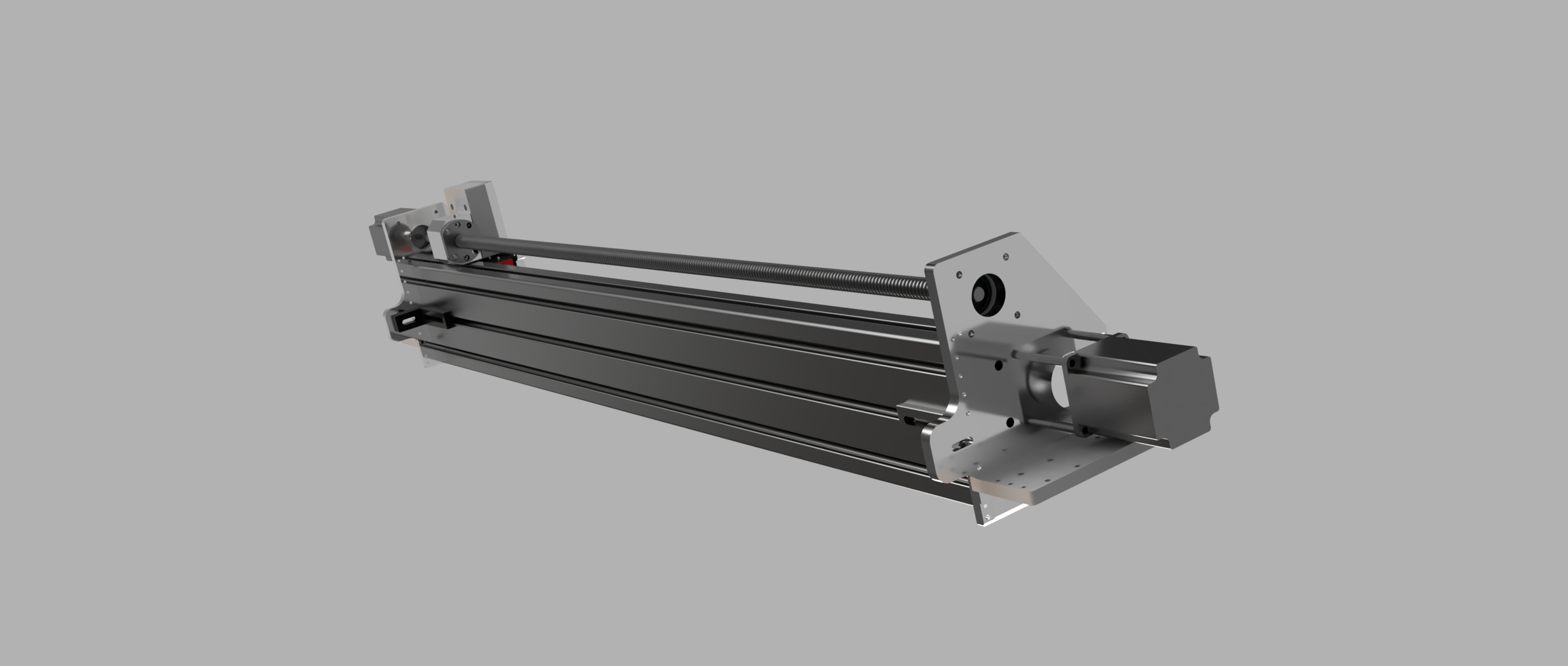
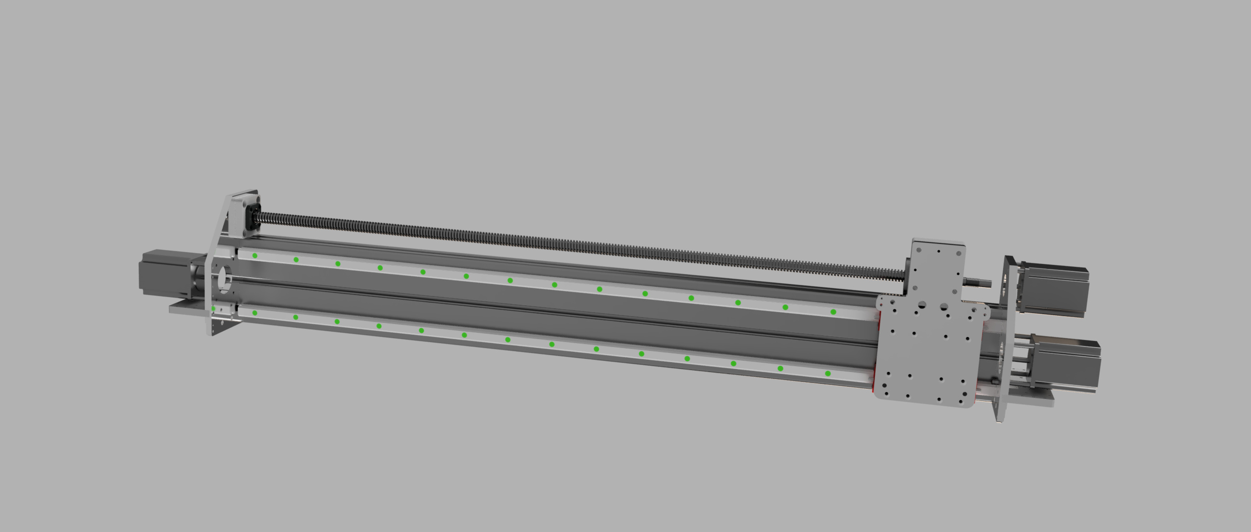
Stage 1 - X-Axis Upgrade (Rails and ball screw)
Stage 2 - Y-Axis Linear Rails Upgrades (still on belts)
Stage 3 - Y-Axis Ball Screws
I am almost ready with the design for Stage 1 and only missing the measurements for the fixed bearing block of the ball screw. my goal is to start the mockup of the axis in November… depends on delivery of certain parts and my available budget
This is what I got so far and I would be happy about some feedback or ideas… maybe someone already did something similar and has some tips and tricks…
As soon as I got everything together and start building the mockup for the axis i will post my BOM… the idea was not to use the the original extrusion for the X and try to always have have a way back… It’s pretty hard to get spare parts here in germany…
i was struggling a while if I should start the project… but I guess i will be pretty fun… but to be honest form a financial point of view it may be better to buy a new machine but i guess that’s not the Shapeoko way of doing things…and I am very curious how much precision I can get out of this…
Nice, I started modeling up an upgrade similar but keeping the belts and just using IGUS rails. I’ll wait and see how yours comes out and the total on BOM. thanks for sharing.
Yes it’s an ITEM Profile 8 120x40 currently the light version. Not yet decided if I may change it to the heavy version to have more reinforcement in the axis. If the heavy version fits in CAD I probably use it. Did not see the heavy version could be ordered online easy as well… If your not a commercial buyer it’s pretty hard to order at ITEM directly but there are enough online vendors selling ITEM compatible profiles. But not any version of them.
already got some EU vendors over here selling the ITEM compatible parts with easy shipping to Germany… At the beginning of the design I wanted to buy the original ITEM parts because of accuracy and the available CAD files but looks like the sell only to commercial buyers directly… so I will give it a try with the compatible ones…
It’s a good point I did not compare those numbers. I was looking for profiles used by others for comparable CNC builds. Do you know the numbers of the r carbide extrusion? Compared to the structure of the heavy version it looks like the section modulus should not be a big issue. But that’s maybe just the opinion of the noobie building he’s first CNC axis… that’s why I did this post in hope of getting some things I missed or good tips.
I’m not a mech engineer, so the calcs below are subject to correction by people with the right qualifications…
If I have the calculations correct (and a correctly assumed Aluminium alloy) for the C3D extrusions then the X beam would be approximately;
58cm(4) along Y axis
106cm(4) along Z axis
Given that this alternate extrusion is 150% the height and 70% the width with a similar wall thickness (the stuff in the middle doesn’t do that much) that all seems reasonable.
This extrusion would therefore be 300% of the stiffness in up / down flex but only 66% of the stiffness in front / back flex under load.
If you were looking to upgrade the performance of the machine, a larger cross section in both directions is likely to pay dividends. I would not replace the C3D extrusion with this one.
The 120x80 profile they list on the other hand;
Trägheitsmoment I x: 277 cm4
Trägheitsmoment I y: 580 cm4
would make for a pleasingly solid frame and is sufficiently stronger than the C3D extrusion to be worth the cost and effort of replacement.
There are various online calculators for determining deflection under load of a beam once you know the moment of inertia and the material which this vendor helpfully provides.
I have found it to be a great source of ideas and examples of what has worked for people and what hasn’t
Are you planning to replace the steppers and control electronics on your machine to drive the additional rotating and moving masses?
I would also suggest looking closely at the Shapeoko Pro before doing any upgrading, decisions the Carbide team took such as running a longer X extrusion that spans across the Y rails to provide extra running room and space for protection bellows over the X rails all make a lot of sense. If you’re buying new extrusion you really shouldn’t be restricted by the constraints of the old parts.
Yeah me neither so i might have been a little to easy in some of my design decisions. I guess that was also somewhere in the back of my mind as I post my design first before i started to build the mockups
My first idea was to use a 120x80 but i wanted to gain more space on the Y Axis… but after soem research and your calculation i think i try to fit the 120x80 heavy profile in my design. This also will be more easy to mount with 6 screws to the plates… I am a little concerned regarding the mounting of the carriage plate the new profile may block off some mounting screws for the carriage plates.
Item has a defelction calculator on their website will give it a try but dont really know operating force will be on the profile… maybe i need some more research in that…
I will also look on the websites you mentioned looks like a good source for ideas…
Yes i started planning to replace the GRBL board even before the axis idea… Currently I have to options in mind.
Option 1 Estlcam Based Controller:
Great controller solution runs in a lot of hobby machines…
Option 2 EdingCNC Based Controller:
It a real advanced controller with great software but not very cheap
The goal is that the new overall controller solution may also fit in a future machine without too much modifications. At the moment I tend to use the Eding solution with the Closed Loop steppers. Will stretch my budget a lot but also the experience i get out of building it.
I will also give the Pro a closer look… The announcement started that hole thing here again for me
very appreciate all the input here so far… i really like the shapeoko community
I have upgraded my XXL to a Gecko G540, UC-300 eth and UCCNC and it is a great combo definitely worth considering. I’m not sure what the cost is compared to your other options.
Here’s a thread where Mike summarised the controller and stepper parts he used;
I decided some time ago though that I would not bother with open loop steppers again, the incremental cost to closed loop steppers from people like stepperonline or to DC servo motors is small enough compared to the time and other costs involved that I don’t think it’s worth the trouble of open loop systems any more.
The Y plates can really be any shape you like, if you look at the X Carve Pro you’ll see their Y plates lean back quite a long way to keep the Z axis above the Y rail blocks. This increases the torque on the X beam but on the 80x120 deflection is likely small. There’s no need for the Y plates to stay within the bounds of the machine footprint, the constraints are your chosen X beam position and maintaining a reasonable distance between the Y rail blocks to minimise the leverage on them. What limits Y travel is the total length of Y block - gap - Y block, just as on the X rail.
Do you plan to completely replace the new Y plates when you go over to Y axis ballscrews? Based on the rendering, you could add bracing between the horizontal and vertical to stiffen up the side to side and rotational flexing there.
As you’re using an XL I suspect the carbide extrusions are more than sufficient for your Y axes.
Do you plan to deal with the lack of rigidity in the machine base?
Regarding your design, how will you attach the rails to the extrusion? Just nuts? Do you have any plans for keeping the rails precisely flat?
I’m thinking about doing similar things to my Nomad and I was thinking of extrusion but ruled it out for lack of precision. My thought was to buy a pre-milled 15mm or 20mm EN AW-7021 plate, bolt the linear rails to it and stick it where the Nomad’s X-axis rods are with a bracket or by putting some beefy threads into the plate.
In case it helps, I’m using the CNC720 on my Nomad and I love it
You might find my thread helpful, I compare controllers and drivers.
Since you’re cost-constrained, it might also make sense to keep the steppers that came with the Shapeoko. If you’re in Germany I could probably send you one of the adapter PCBs I made for the Nomad, though I’d have to think some more about how useful it is to you. My first board might work out of the box, depending on which stepper drivers you use. The later board is nicer and more compact but also very focused on the ESP32 and TMC5160.
LinuxCNC was also on my list of controller solutions a while ago but dropped it in favor of the Eding CNC. The Controller and Simple BOB Breakout board look like the better way to go al least for me. But I guess LinuxCNC is also a really cool solution. How happy are you with your solution?
I am not really cost constrained for the mod… Cost will just dictate the pace if the mod I will definitely replace the steppers. The controller and steppers could be used in a future machine as well. But thank you for the offering.
The only way I decided not to go was buying a complete new machine for now. Since I love my Shapeoko and the modding of it.
I will use my shapeoko to cut the plates and also the surface the material for the plates. if that does not work as intended I will look for a way to get it surfaces somewhere. I have more concerns how flat the cut of the extrusion will be. I dont have a belt sander or something similar if the cuts are not flat. Bujt the first comments of others ordered at the webshop said they are good cuts so we will see…
I mean the linear rails. They need to be as straight as possible to keep your machine accurate. Since they’ll be attached to the extrusions, if the extrusions aren’t perfectly straight, the rails won’t be either.
I was wondering whether you had any ideas on how to mitigate that. Like will you face the extrusions or use shims or something to get the rails perfectly flat?