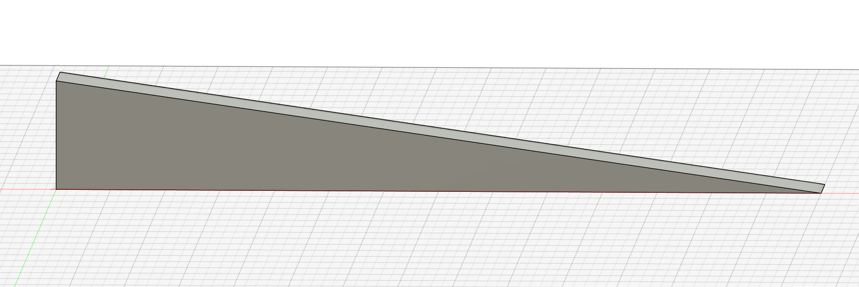
OK, I have been working on this problem a good part of the day and I need a break. I so far I am taking the long way around this issue, and I need to know the right way to do this. I am attempting to cut a 10 degree angle on the top surface of my work-piece. any help would be much appreciated.
Do you have Carbide Create Pro?
If so, see:
If not, can the piece be rotated? The profile is easily drawn up if it can be cut from the side.
Otherwise, see:
part shown is just the section needing the angle entire piece is much larger and must maintain this orientation. I do not understand the gradient usage.
Upload the file you are working on and we will walk through using the gradient to apply the desired angle.
I have just been trying to figure this out so do not have part actually drawn up yet . wanted to find solution first. the above pic is from fusion
If you are using Fusion, why not use its CAM?
That said, if you’ll export an SVG or DXF or make a screen grab or something we can walk through this w/ you.
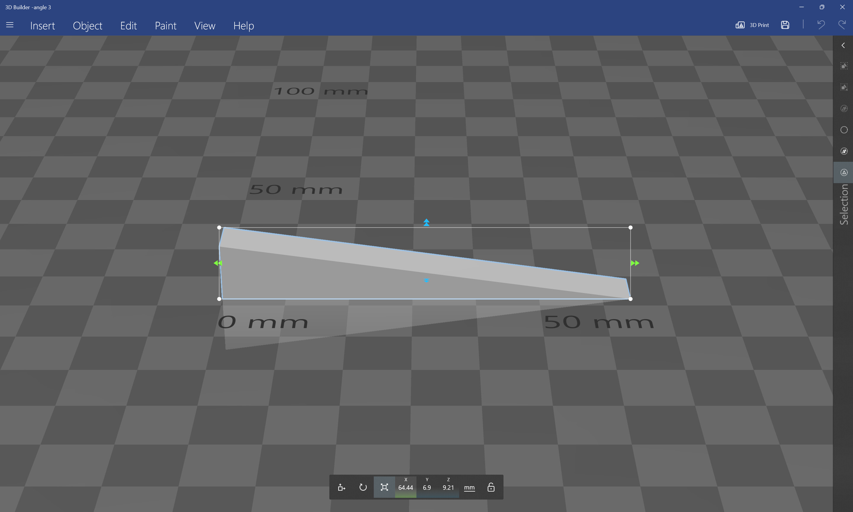
angle 3.stl (484 Bytes)
have not yet tried to use the CAM in fusion, ever
taper test piece.c2d (272 KB)
That:
is what I was referencing above, and is about as good as things can get w/ Carbide Create (bundled) unless the desired angle matches the taper angle of a V tool
Alternately, work up a fixture to hold the stock at the desired angle and just use a series of pockets — the search term for this is “sine plate machining”.
Hang on and we’ll walk through this in Carbide Create Pro using the pixel image mentioned above.
I think that if you are doing this part in F360’s Design tab, that using it’s Manufacture tab for the toolpaths would be the best way to cut that. I would use a 1/4" or larger ball endmill and a Ramp toolpath to make this feature.
The other option if you have designed it in F360 is to export it as a mesh (STL) and have Carbide Create Pro 3D machine it.
1 Like
Basically that is what I have been doing manualy. can’t do fixture because of rest of piece.
1 Like
tried the STL option I’m still lost . Might try the other manf tab though
1 Like
F360’s toolpathing is a lot more detailed and takes a ton more effort and time to learn. It’s absolutely awesome for functional parts, but falls short on decorative stuff. I still use CCPro a ton as well. It’s 3D mesh options and v-carving functionality are much better.
1 Like
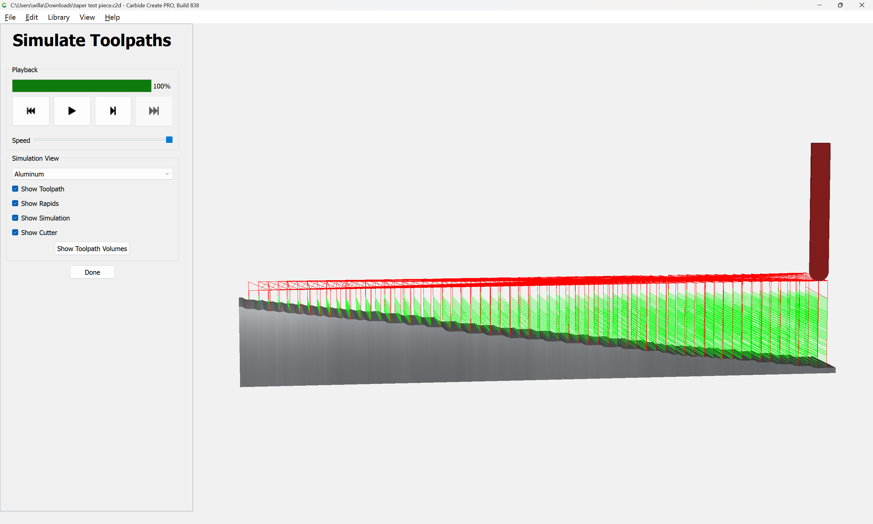
The easy way is to use the STL:
The file is:
Draw geometry:
Import the STL:
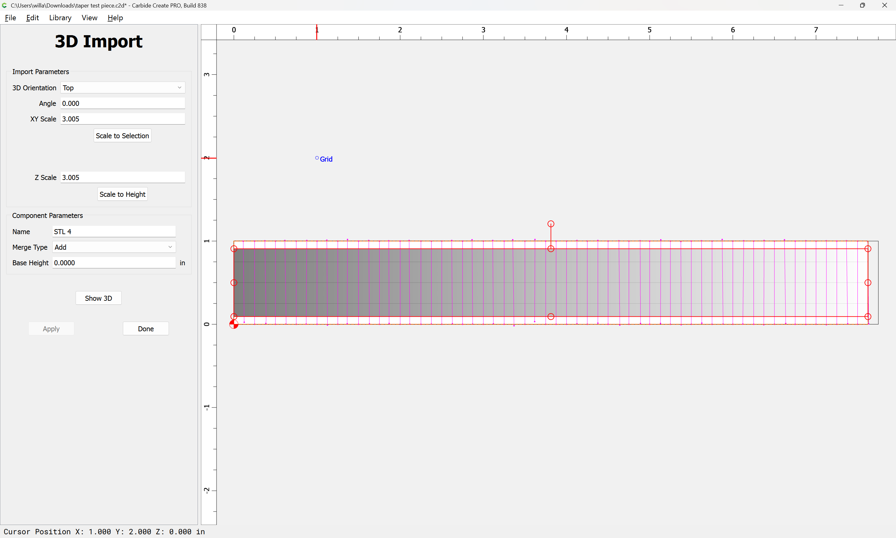
which imports a bit too tall:
which may be adjusted by changing the stock size or model.
Then apply 3D toolpaths:
j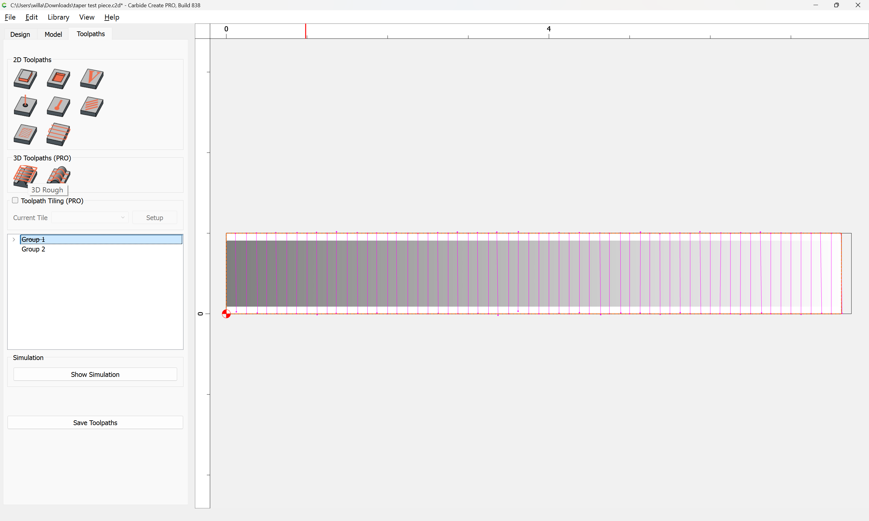
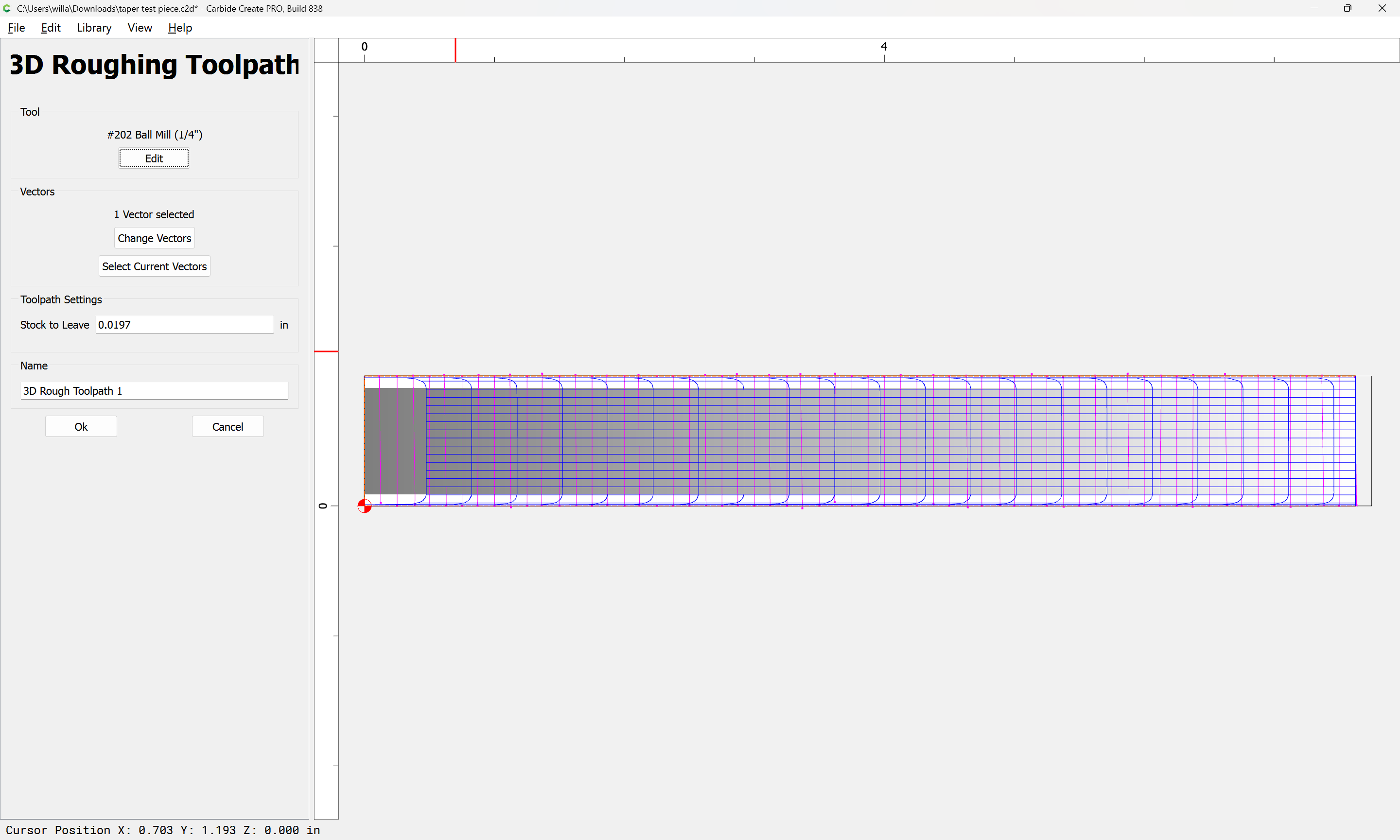

adjusting the stepover.
Next, we model using the file.
2 Likes
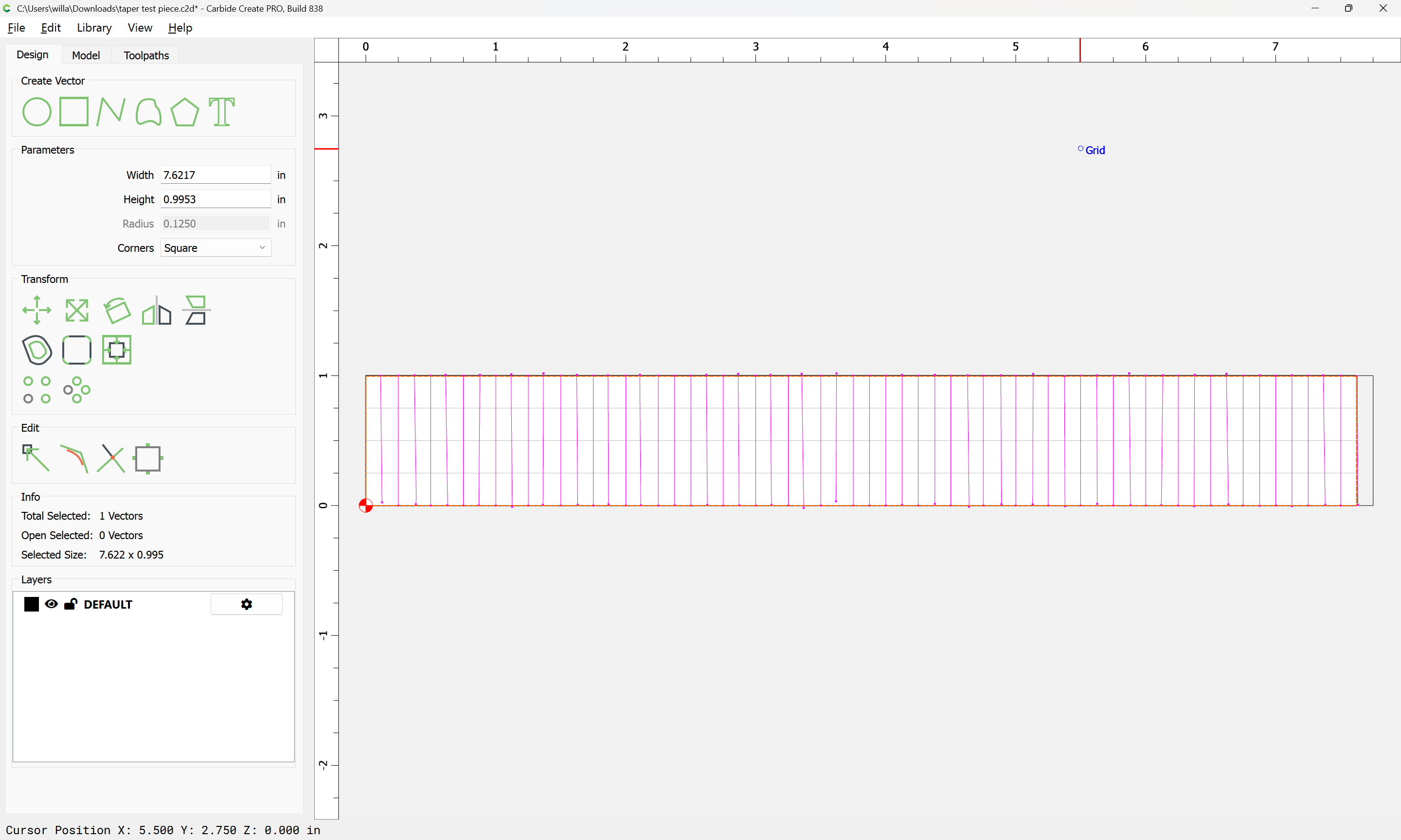
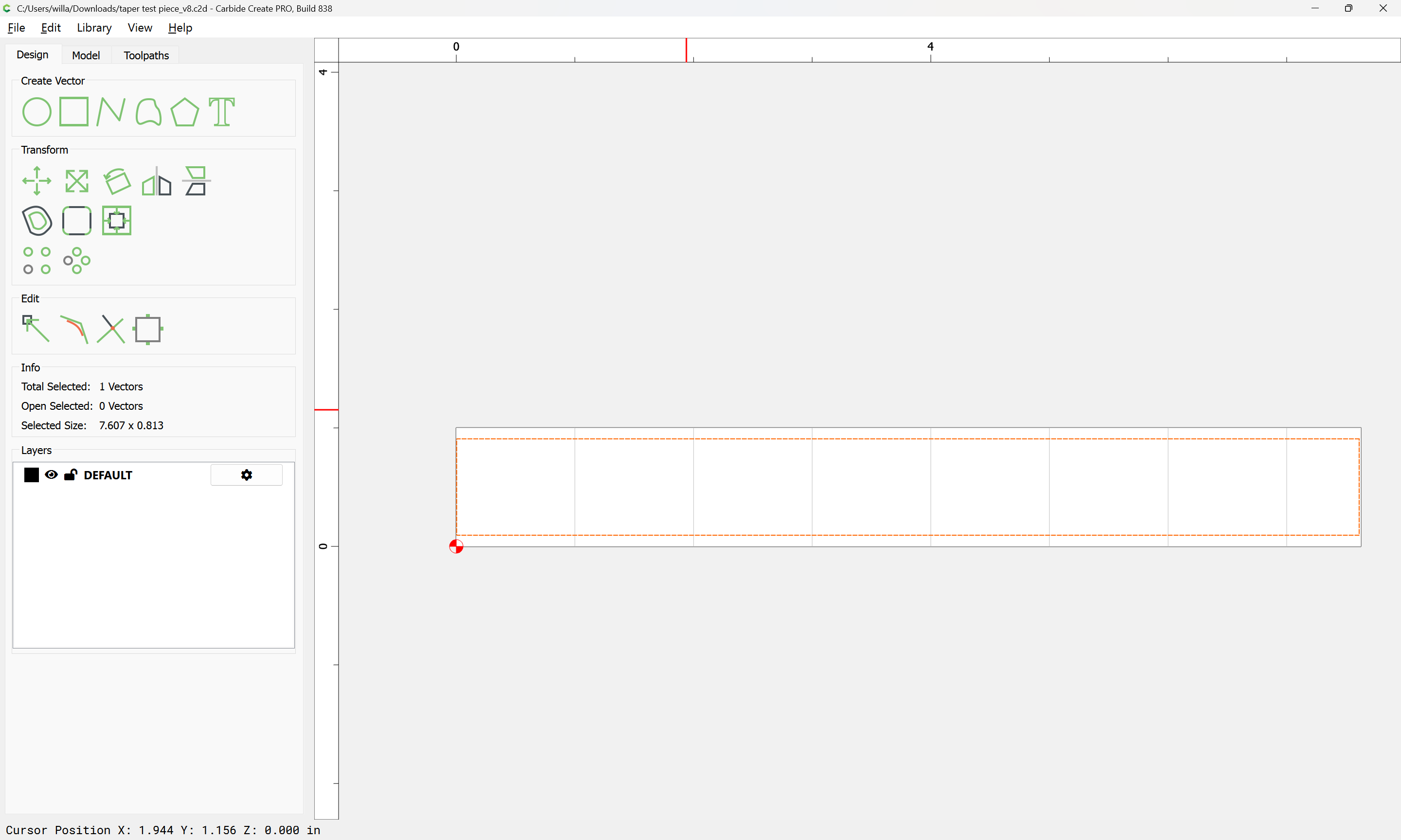
Draw a rectangle of the desired dimensions:
Switch to the 3D modeling tab:
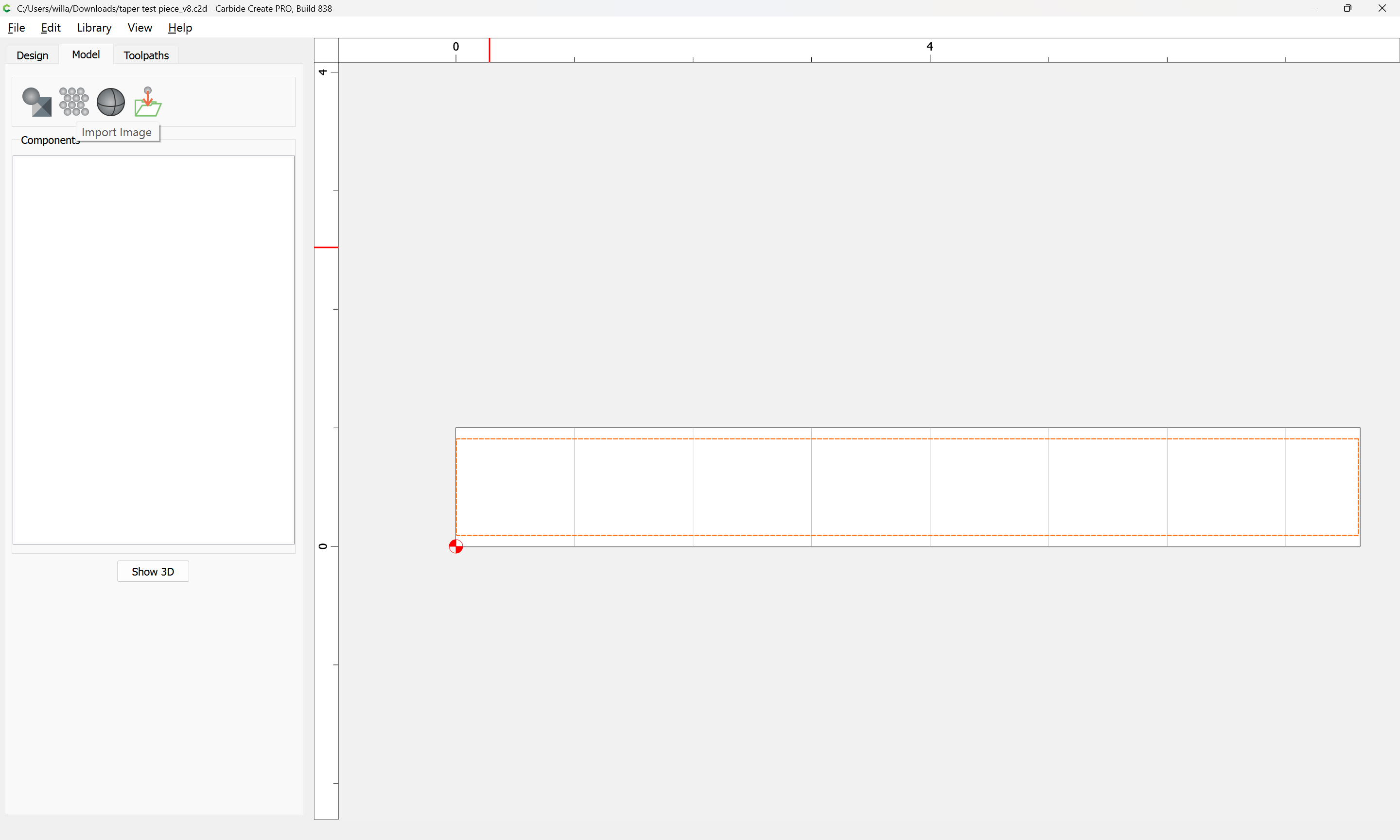
Import Image:

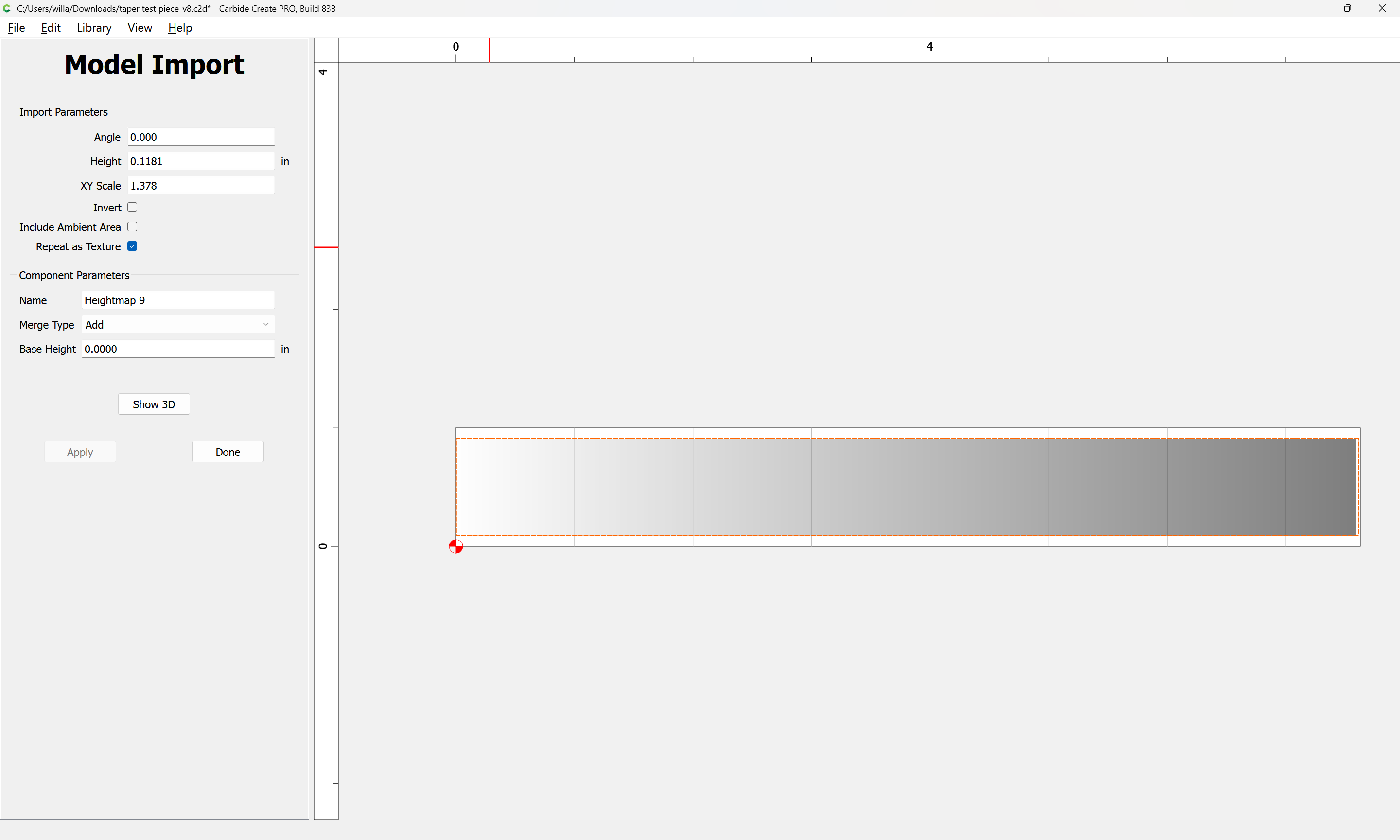
selecting a left–right gradient:
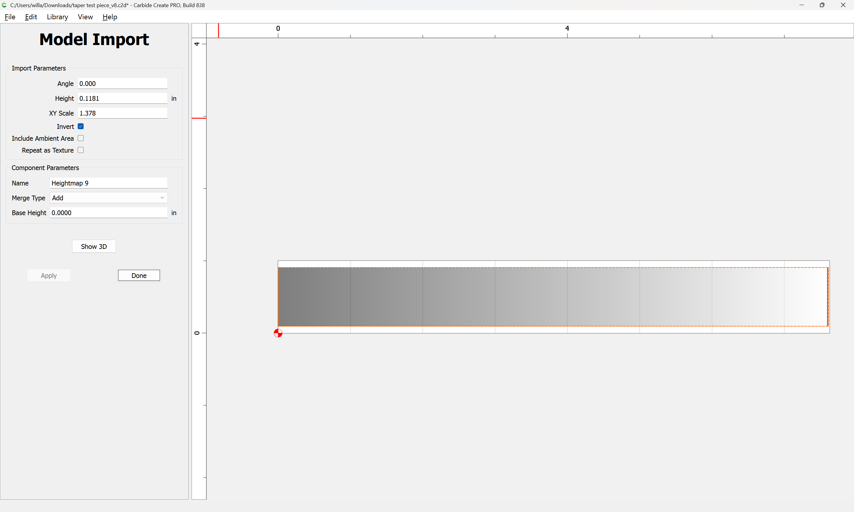
If need be, check Invert:

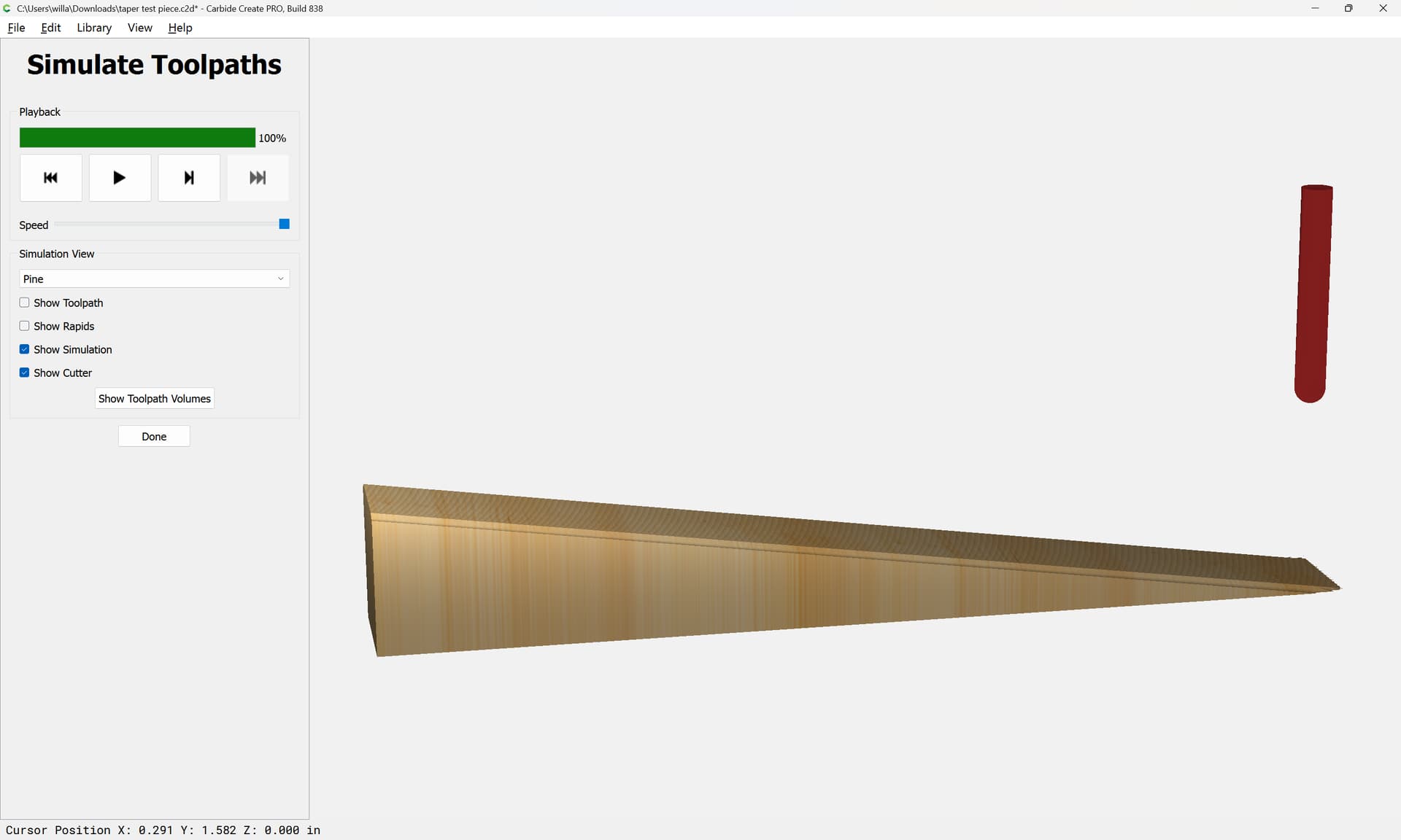
Adjust the Height until one arrives at the desired angle:
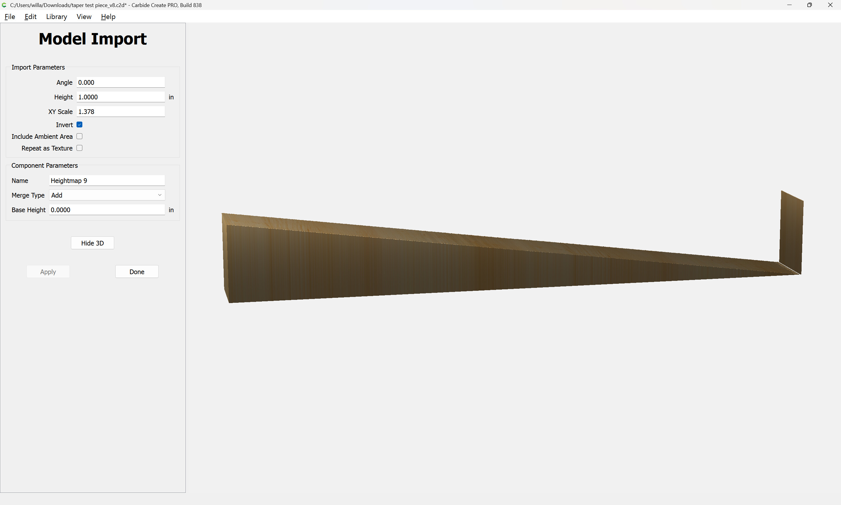
4 Likes
When I need to have a tapered surface I place blocks under one edge to tilt the piece to the correct angle and surface the piece as if a flat piece.
I 3d print my spacers to exact height and shape. They could be machined.
If you have a planer, I did similar. Spacers glued to a temporary sled to get slope right and feed the piece and sled through many times. Until I got the desired “thickness”
CNC route is easier.
3 Likes
I will have to play with this method looks promising thanks
Well I successfully made it through the tutorial for generating the g code in fusion. I must say that looks very promising …a lot of steps to remember. more to come later on thanks for the help
1 Like
Not sure if your trying to figure this out because you want to learn how do this using the software but if not and you just need to get it done to finish a project then you could just prop up one side until the surface of your material is at a 10 degree angle, clamp it down and surface the material. I don’t have the pro software so I use this method.
1 Like