The last week I’ve ported this tool to also be browser based, and it has now reached a level of usability and gcode quality that I’m happy enough with it (pictures below)
So why directly to gcode? First, I really like Carbide Create, and use it all the time for all kinds of designs. And with STL2PNG, you can even use it to cut basic STL files.
However in the process of going to a bitmap, you either lose details, or end up with a bitmap so high resolution that CC more or less croaks on it.
(and it seems I like high detail, large cuts, of landscapes, such as Red Pin Terrain carve where single blocks/houses are visible enough to be able to put a pin in the target house and The three volcanoes of N Oregon and S Washington which was a 8"x12" cut at full detail… what’s a few million vertices between friends).
By bypassing the PNG conversion step, the detail loss is avoided.
The performance is not quite at the level of the native C++ tool yet, but also not horrible even for STL files in the 100 megabyte range (pro tip: don’t feed a 100 megabyte STL file to Fusion 360).
There are some minor limitations / todo items:
Only 1 roughing pass (e.g. single tool) is currently implemented (the C++ version allowed for multiple tools to be used consecutively)
The tool library is limited to the bits I use regularly… easy to add bits, so let me know, but I might need to implement a tool editor of sorts
There is no graphical preview of the cut yet, only downloadable gcode
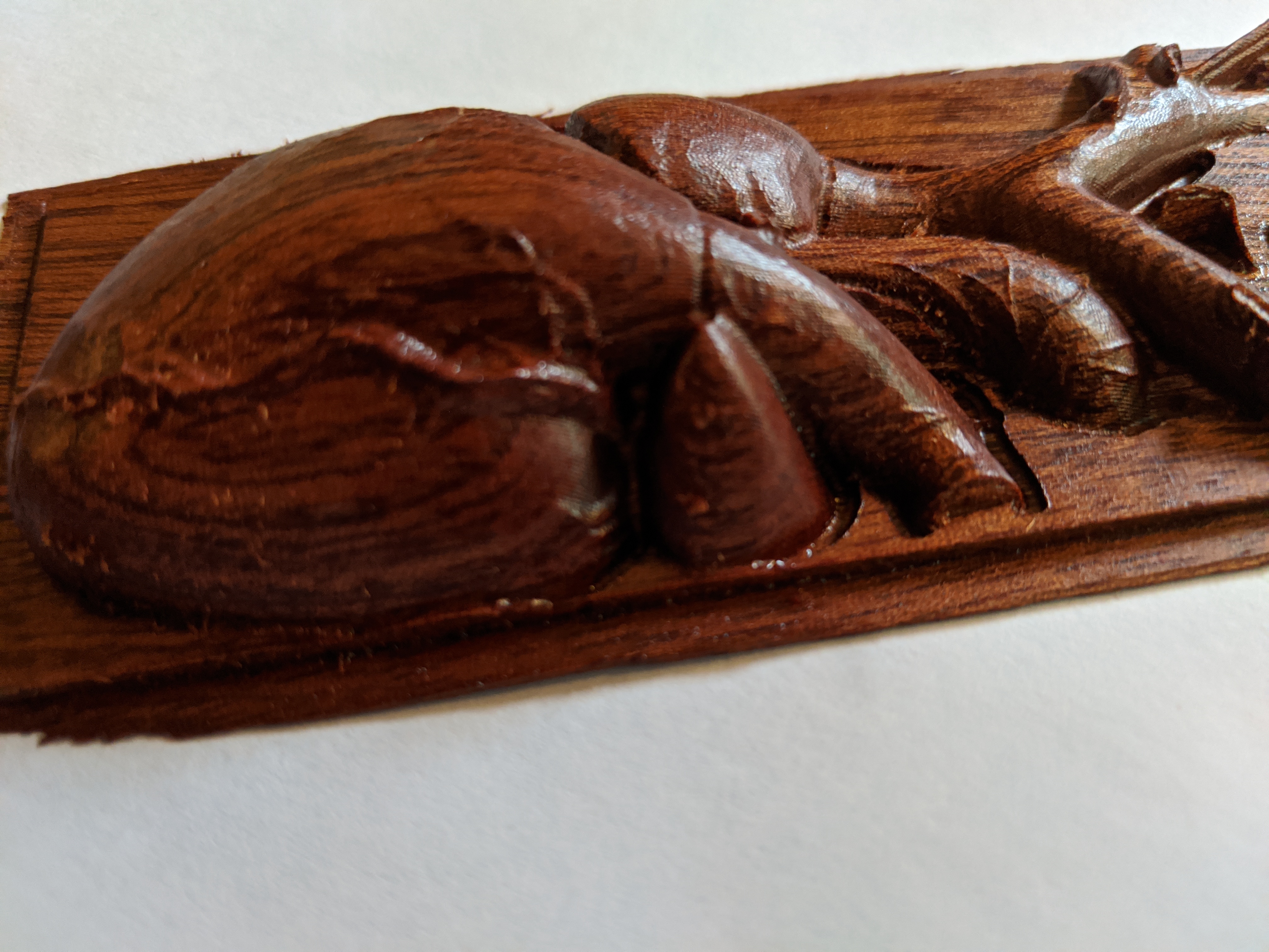
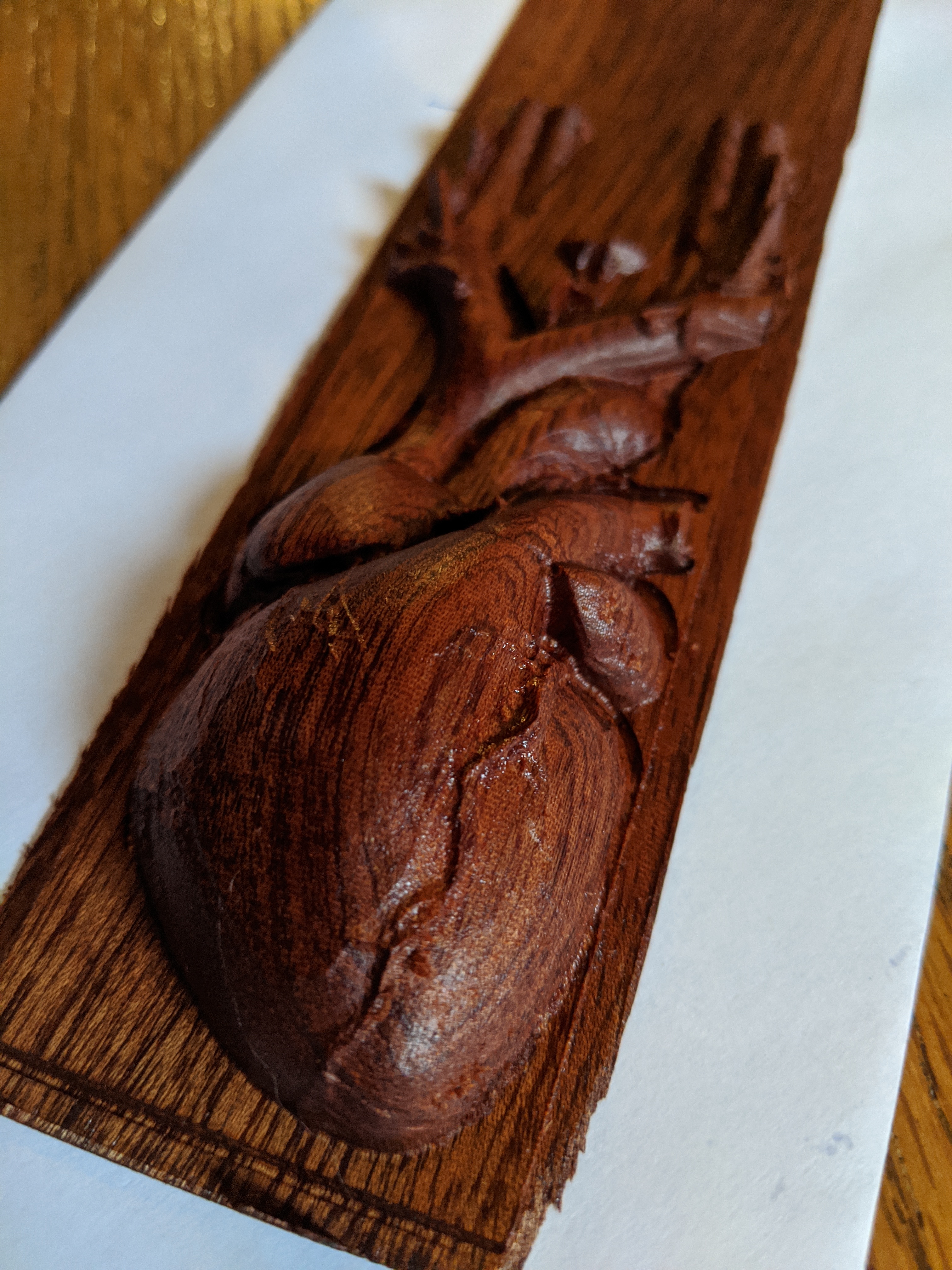
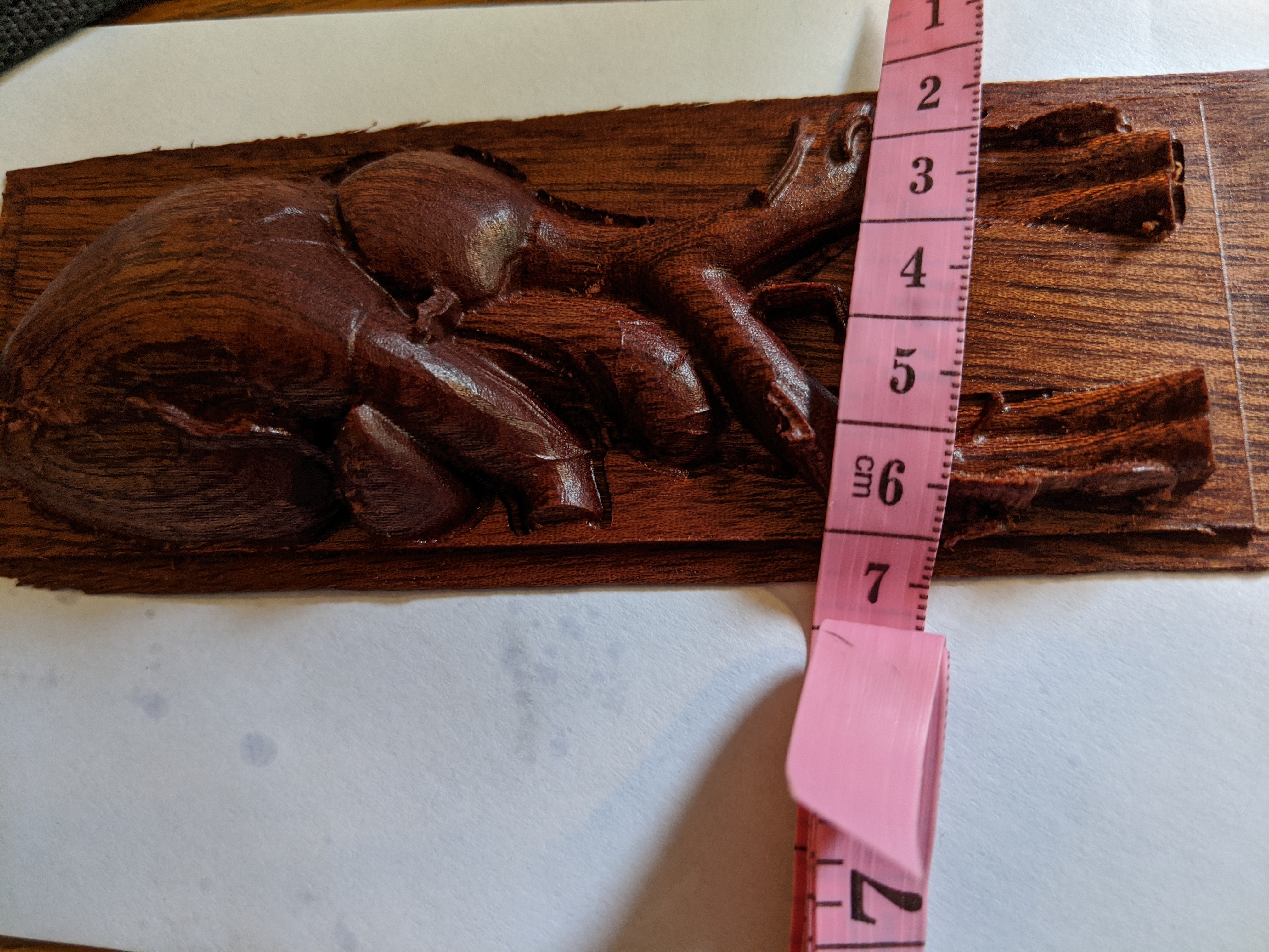
Now for the pictures; the first thing I cut with the C++ tool was a heart that I found on thingiverse (https://www.thingiverse.com/thing:3260660) so I decided to use that again.
In the current iteration, the details (vains etc) come out absolutely awesome. The only processing done was to put some oil on the wood; no sanding was needed.
It looks really nice, but I have a few questions. Did you do the entire project in one pass? Not a rough and a finish pass? What tool did you use, and how long did it take? I’m debating on whether to use the new version or try my hand at the old version for this topo map I am about to cut.
it was two passes (the gcode generates that)
I used a 1/8th inch straight but for roughing and then a 1mm tapered ballnose for finishing using 0.1mm for stepover
it took a bit over three hours to cut
What would you recommend for the 1mm Ballnose for speeds and feeds for mahogany? I don’t want to snap it first time out. But at 0.1mm step over, I kinda want to hurry it along.
50ipm seems quite fine for me, and I could even go 130% on that in CM.
The only thing I like to do is (in CM) set the very first pass to 50%, just to make sure that there is nothing unexpected (in my cut above there wasn’t… and I’ve made the tool use the roughing bit to make a “moat” around the design to create a bit of extra space… but well you never know)
(For ease of argument let’s assume the finishing pass goes for left to right and back…)
So in the Y direction, discrete steps are made at an increment of the step over… sort of the definition of step over. This step size is basically defining the total cut time since it determines how often you go from left to right and back, e.g. the total travel distance, and distance is time in cnc.
In the x direction it’s a bit more dynamic, the “price” for being fine grained is just compute time not machine cut time. The tool currently will do this no coarser than the step over distance, but for example in areas of high vertical gradient, it will go finer. I also expect in the future to add more dynamic heuristics to this as finer in the right places impacts how the very fine details come out.
I find this topic really interesting and it’s nice to see this kind of implementation, so thanks for sharing!
May I suggest: As far as I understand, in your get_height_tool-function, you look into ±x and ±y directions to check the heightest height in the area of the tool. You can compute a local gradient there that gives you the direction of the maximal increase/decrease in height and using this you can probably save a lot of height tests around the tool. This would be valid as long as you stay in the same triangle, though.
I need to think that one through… yes that function tries to find the highest point in area, but with a twist… it needs to take the geometry of the endmill into account, e.g. it needs to compensate for the ball shape of the ballnose… it’s not a strict “highest point” per se.
gradient can still be interesting but needs to figure out how
the javascript code is still a bit messy; this is one of my first things written in javascript so a lot of the code likely is not “native” to JS, but will read more like ported C/C++ code (which is what it is)
But it’s a work in progress… at this point I’m happy enough with the quality of the output for a version 1.0 kind of thing… but loads of ideas to be done (the C/C++ version still has several features for STLs that this code does not have, including some quality improvements)
So, I gave the new tool a try. Unless there is a trick I am missing, there seems to be a fatal flaw. After the tool change there is no way to change the Z height. Up until that point everything worked really well.
Awesome, thanks. Bit setter is currently on the top of my wish list. Hindsight being what it is, I definitely would have gone for that rather than the track kit to start. After that it’s a tie between the new Z Plus and the bit runner. Kinda kicking myself that if I had waited a bit longer it would have come stock with the Z plus and the sweepy. Cest Le vie.
Now I just have to make more than wood chips so I can justify spending more money on upgrades. I think your tools are going to be a great help in that. Finding out that I can’t actually use MeshCam had put a kink in the plans.