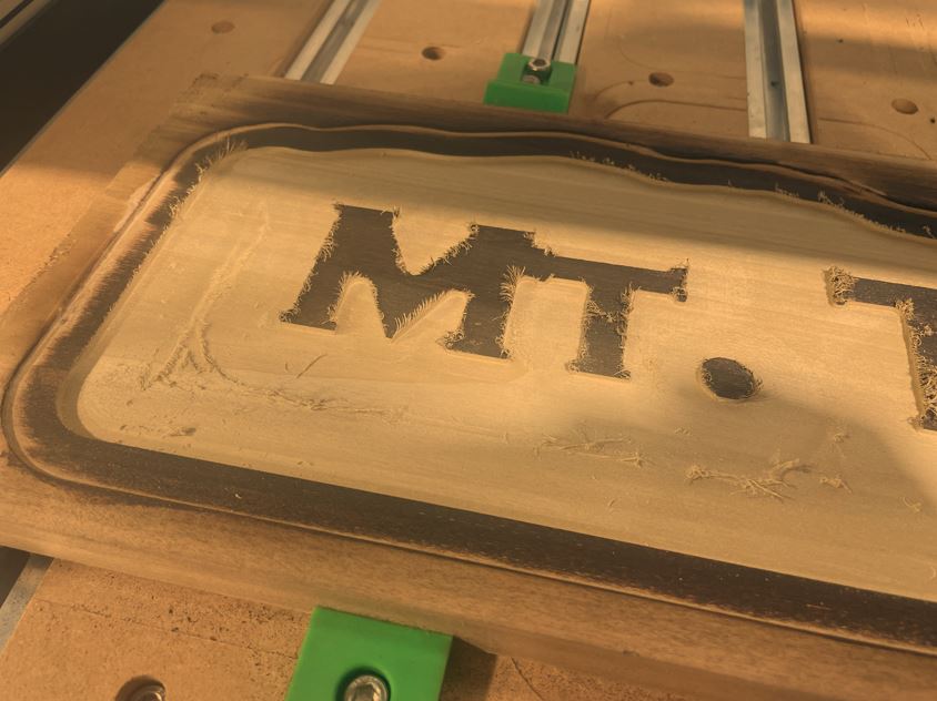
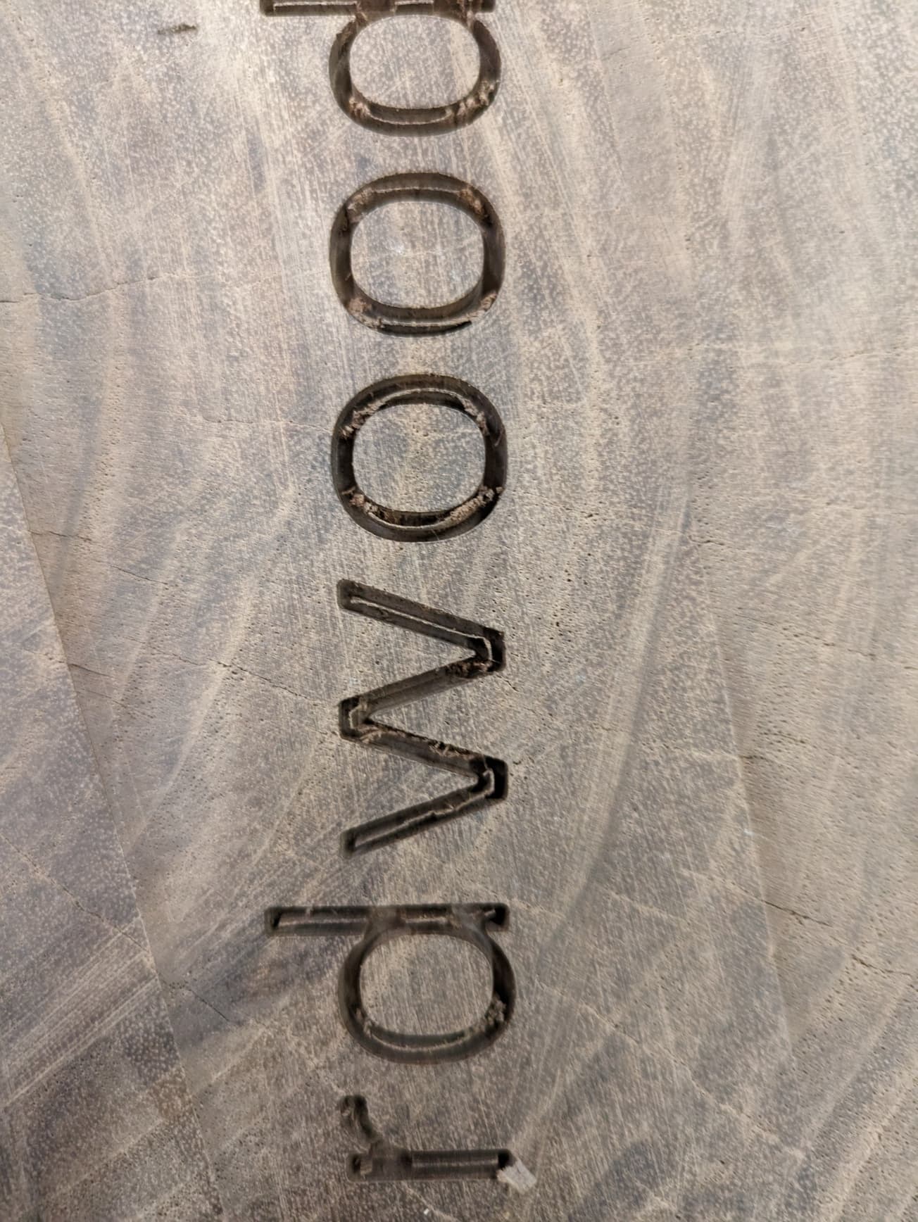
What I can’t understand is WHY this happened? The rest of the part came out pretty good, especially considering my first project. But I’m a little confused by this. I’m guessing I need to step up to a paid CAM software in order to adjust toolpaths? Thinking about having the path go left to right in this section instead of up and down. Either way, I’m open to suggestions on how to make this work out.
I also tried running a separate clean up toolpath - same tool, much slower feed and stepover.
Unfortunately, that didn’t do the trick, either. I’m baffled, because the cutter never touched down. I started the cutting at the proper z depth, but for some reason, it turns out the material is a full 0.030" lower than the cutter. I verified this by zero’ing the machine and measuring by hand. Any ideas why this would be the case? I’m using the Bitsetter and set the bit length as per SOP. I’m totally confused, and at least for now, not confident in my abilities to make consistent/precise parts.
If someone is willing and able, I’m uploading my file here. Help is much appreciated!
In your file, the Z-zero point is at the top of the stock material. Could you describe your process for setting the Z-zero at the top of your stock?
Maybe run thru this video: Movements + Zeroing (carbide3d.com)
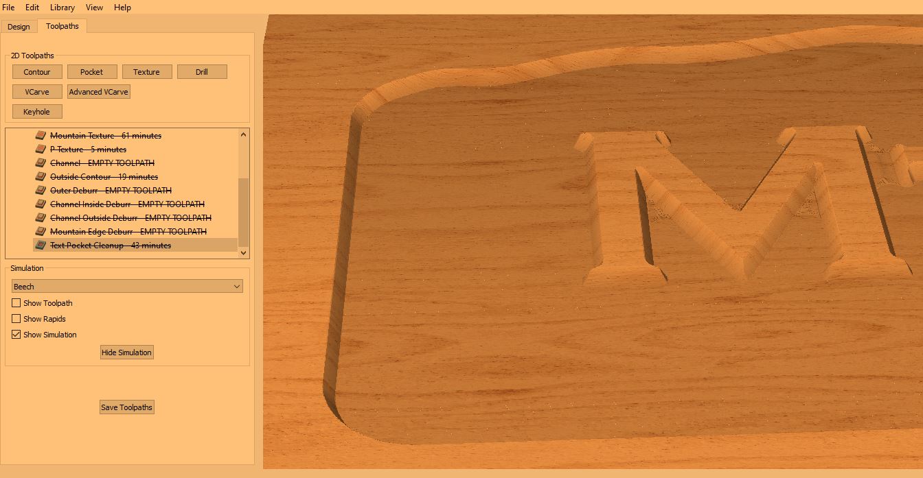
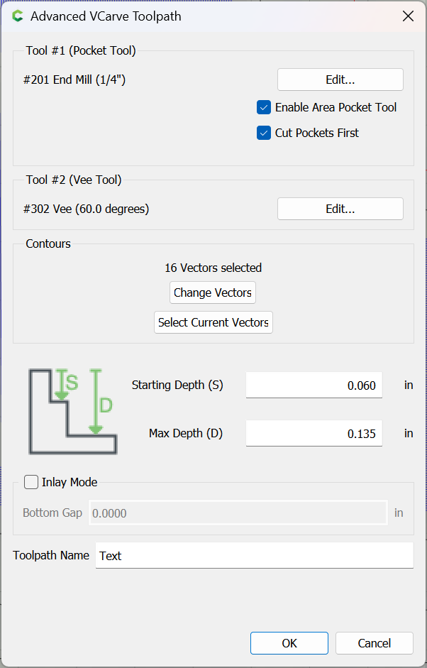
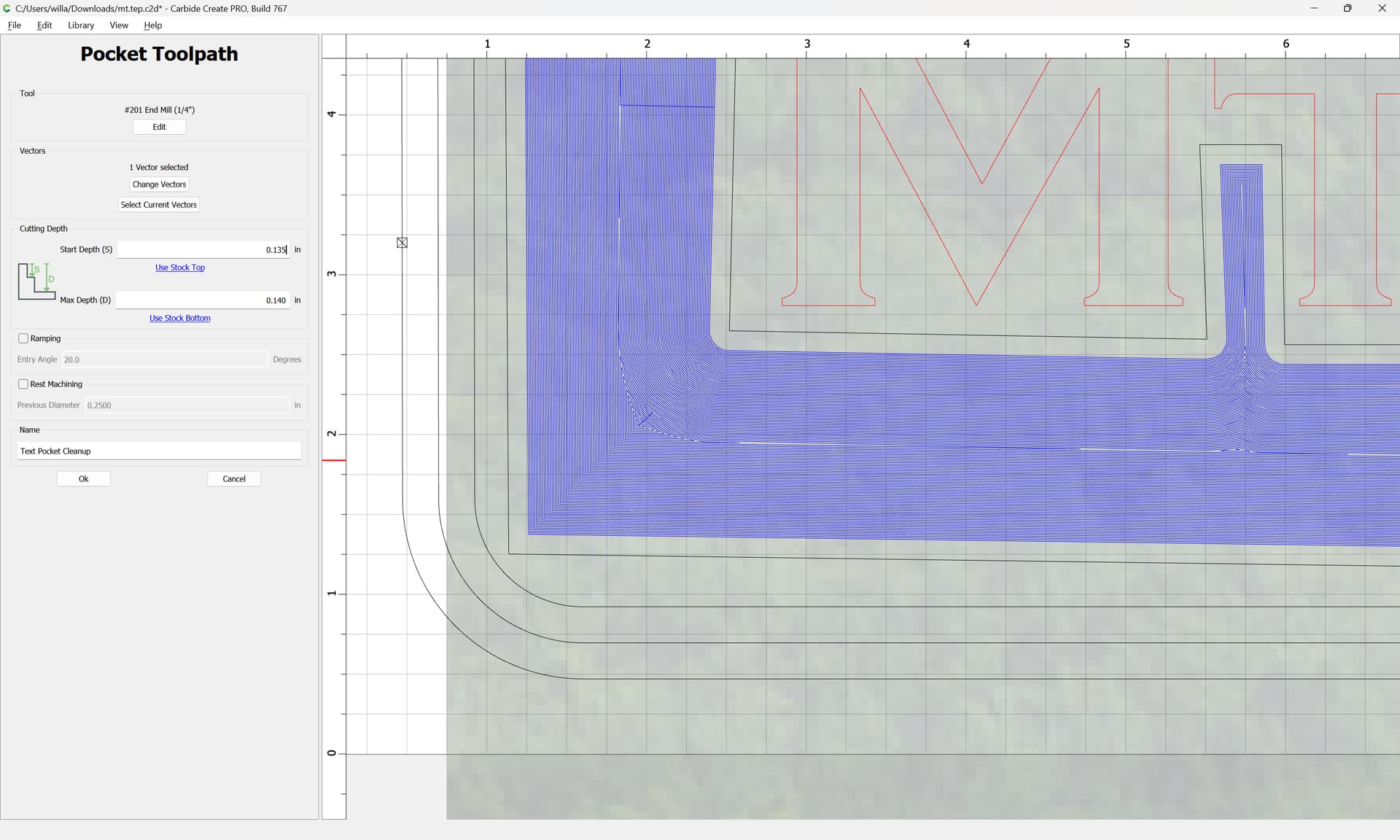
Your Start Depth is set at 0.13 inches, while your Mac Depth is set to 0.14", so only a single pass is made, and your file had an Advanced V carving toolpath which was set to cut that to a depth of 0.135":
If you want a cleanup path to actually cleanup, the best thing to do is to adjust the Start Depth and Depth per Pass accurately, and so that multiple passes will be made, so:
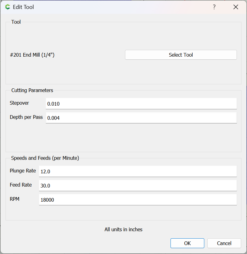
Reducing the Depth per Pass to less than the thickness of material which the toolpath will be removing (0.005") will cause two passes to be made — the second will remove 0.001" of stock, which with a sharp tool in good condition should work well so long as the material allows that thickness to be cut away without rubbing.
Thanks for the quick, thorough response. Few things:
My initial v-carve depth was set of 0.135". My clean-up attempt started at 0.130" knowing that I’d likely not cut away any material. But I wanted to start the cutter above the material to check in on the progress. My max cut depth of 0.140" was just a rough estimate of what it’d take to remove the high spots. I didn’t mic the feature, but figured .005" would get me close without damaging the rest of the surface. However, as I mentioned, the actual depth of the pocket was 0.170", so it’s no wonder my cleanup didn’t remove anything. I ran the cutter for almost an hour and never actually touched the cutter to the wood!
I appreciate the feedback on the depth per pass. I wasn’t sure how that would be implemented in the machine as I just used the defaults for most of those parameters. But, I did notice the numbers and was waiting to see how this experiment played out.
So my two questions:
Why was so much material left after those initial cuts? I was kind of using the simulation as gospel, which clearly was a lesson learned. I was not expecting to do a clean-up pass…
How come the actual cut depth of the v carve pocket was deeper than specified (0.170 vs 0.135)? This is the part that baffles me the most since I’m in a climate controlled shop, the part fixturing wasn’t adjusted, the tool length was set with the bitsetter, and my Z height was set manually on the material face. And for what it’s worth…the relative scale of the features looks good good over the rest of the part.
@Chaotica I jog the cutter to my desired location, in this case, the lower-left corner of the material stock. I find this easiest with the vee cutter. I set x-y first and then lower the z position until the cutter just kisses the surface. I wasn’t concerned with an extra .001 or two of depth in either direction as I was just making a sign. But in this case, the deviation was about 0.030" which is strange to me.
In this case, I surfaced the stock 0.060 to remove some surface imperfections. I then did a v-carve pocket which started at 0.060 and cut to 0.135. My cleanup was set to finish at 0.140, but that’s when I noticed I was cutting air with a 0.030" gap to spare.
Seems like you may have lost Z-axis steps during the job. I’d test the Z-axis by jogging it around after setting the Z-zero on something…make sure the stepper motor connectors are secure & not getting flexed around. Then check to see if the Z-zero goes back to the same height. Then jog it around again while flexing the motor connectors to see if it stutters/clicks/grinds to get any idea if the connectors are a problem or not. Then check to see if it goes back to the same height again.
You may need to decrease step over. I cut a sign the other day with a #122 1/16" bit and it left a small sliver just offset from the middle of each letter. I just used some carving tools and a brush to clean it up. If I had noticed it before removing it from the spoilboard I would have modified the tool path and ran it again. However I had removed it and it was an irregular shape so I had to manually remove the left over wood.
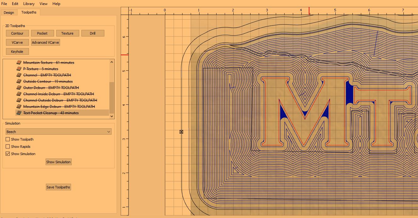
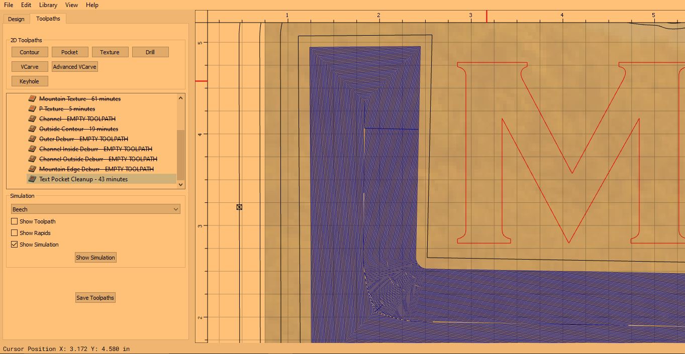
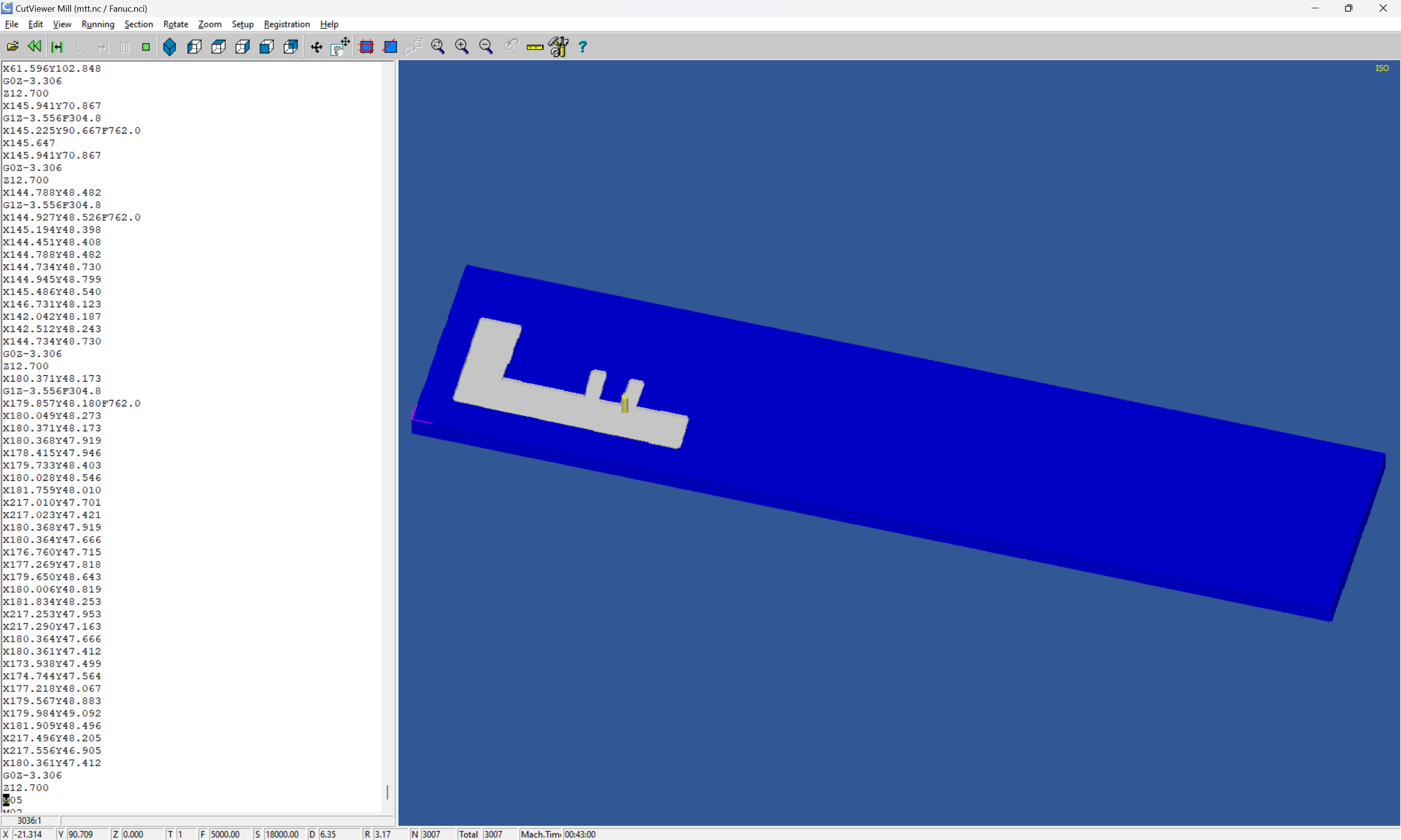
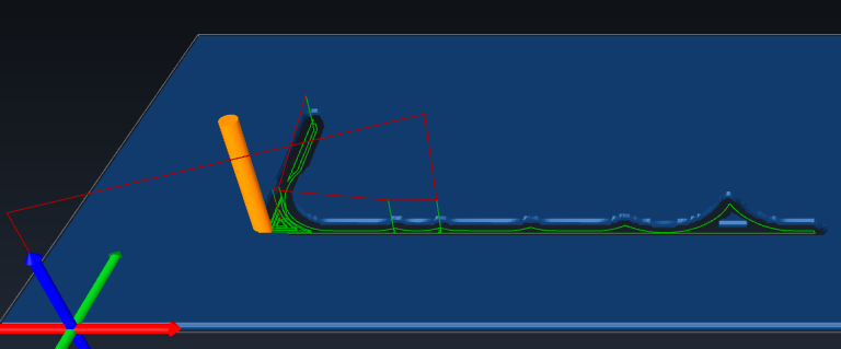
Your Adv V-Carve path starts in that area. It mills out the center then starts to step outward to finish the pocket. The first cut in each region is a “slotting” cut. i.e. the cutter is completely engaged and cutting it’s full width. This exponentially increases the forces on the tool.
It looks to me like somewhere, about where I stopped the simulation, those forces caused some unwanted movement & resulted in ‘lost steps’, about 0.030 - 0.035" worth.
Possible solutions for the next job: Lobby for ramping in Advanced V-Carve. Rough out the pocket, then cut your Adv Vcarve to full depth. (after double checking your Z zero didn’t move).
Your cleanup pass cuts to 0.140, but you said the pocket is at 0.170. I would program it at 0.170.
Then set your Z zero for the pocket by touching off the bottom of the pocket, and setting Z to -0.170
Haven’t seen any issues with the connections (that I could find, anyway). The odd part is the other than the actual floor being numerically different than the program, it’s very consistent with good quality overall…
Appreciate the thorough response. What software are you using for the simulation?
Any thoughts on how to address the full slotting load? Is there a way to slow the feed down for the first cut? Or do I just reduce the z depth?
Question on the “lobby for ramping”: can you expand on this? I’m not following.
On the cleanup pass, yes, it was set to 0.140" in the program, but the actual depth was measured at 0.170" when I realized it wasn’t cutting. I measured by hand to understand what was happening. Unsure why it went deeper than desired. But as I mentioned above, the overall quality was very good (aside from the stepover issues).
For the full slotting, ramping can help. Make sure the ramp has a small enough angle that it’s ramping the entire first cut before getting to the cut depth. I use 2°-3° ramps frequently. First cut feedrate control would be really nice. Higher end CAM software has this ability specifically for pocketing. They also have spiral ramp engage for closed regions. I use NX (I work for Siemens. I otherwise couldn’t afford it.)
“Lobby”, meaning ask/influence/beg them to add the feature for pocketing in AVC.
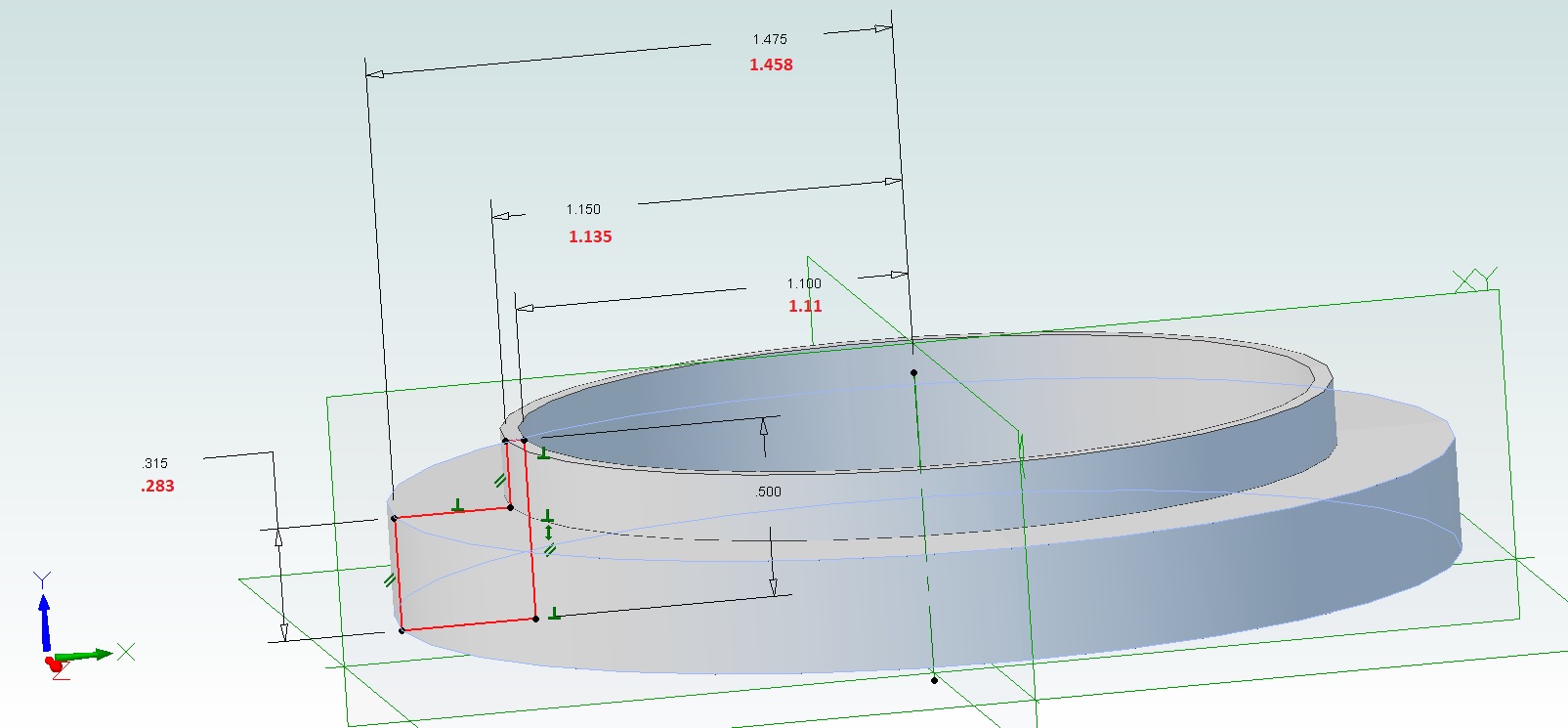
My journey continues. This is a slightly different problem on a different part, but it all boils down to the machine doing something unexpected. I’m at my wits end. This was a simple spacer for a motorcycle shock made out of HDPE.
Black dims are as designed, red are as-measured. I’m not sure what I’m doing wrong, but I’m losing faith in my abilities to turn out good parts. Any ideas?