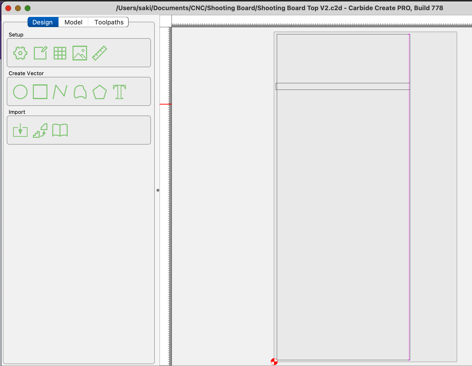
Rather than cut a contour, offset by endmill diameter plus 10% and cut as a pocket down to at least tab height — where possible avoid slotting and add geometry and cut as a pocket
and/or
and consider leaving a roughing clearance and taking a finishing pass.
Also, check in w/ the folks at support to see if one of your Y-axis homing switches needs to be adjusted.
So, for context — and to help anyone else who might be confused — are you saying that cutting squares using contour toolpaths all the way through (i.e., slotting) can sometimes result in corners that aren’t perfectly square because the endmill is engaged on both sides during the cut, which can cause tool deflection and lead to slight inaccuracies?
Before I check in with support about the Y-axis homing switch, would it make sense to try cutting a very shallow contour first to see if that cuts square?
Also, would using a larger bit, but running it at a slower feed rate help reduce deflection and improve squareness?
I’m still having issues and would like to try to square the X and Y of the frame itself…and to the spoilboard.
The suggestion, “loosen all your hardware” is not helpful to me, so I’m curious if anyone that has dealt with this knows exactly what screws or location of actual screws that need to be loosened so I can adjust the diagonals of the frame?
Saki, the only way to square the machine is to “loosen all your hardware” on the Y axis/bedrails and is just the opposite of what you did when you assembled the machine following the manual.
This term means you need to remove spoil boards, loosen the T-Tracks and remove them (This is the only way I would do this, the T-Tracks are machined with fairly tight tolerance and might not allow the movement you need for true alignment).
Then you can loosen the bed rail hardware (bolts) from the Y axis themselves. Imagine you have to move the machine to a different location and the only way to do that is to disassemble it and put it back together.
Follow the assembly manual to square the machine and then re-assemble as you did the first time.
Okay, so ‘loosen all your hardware’ just means loosening the screws that attach the left and right Y-axis rails to the three crossbars (baseframe members) underneath the machine - is that correct?
Would you say the below steps are accurate for squaring my Shapeoko 5 Pro 2x2 ?
How to Square the Shapeoko 5 Pro 2x2 (Using Official Manual Terms)
This walks through the steps to square your Shapeoko 5 Pro 2x2, ensuring that the Y-Left and Y-Right assemblies are properly aligned and the X-Axis Gantry is perpendicular.
These instructions are based on Section 2.9 – “Square the Machine” (Pages 21–22) of the official assembly manual. All terminology below is based on Carbide 3D’s documentation.
Parts Involved (Official Terms from the Manual)
Baseframe Members – Three horizontal aluminum rails that sit directly on your table and form the structural foundation of the machine.
Y-Left Assembly – The left-side unit that runs front to back, containing a motor and linear rail. It bolts to each baseframe member.
Y-Right Assembly – Same as the Y-Left, but on the right side. This one includes the Carbide 3D logo on the front plate.
X-Axis Gantry Assembly – The crossbeam that connects the Y assemblies and carries the Z-axis and spindle. Moves front to back along the Y assemblies.
Hybrid Table Extrusions – Aluminum rails that span the Y assemblies and support the MDF strips.
MDF Strips – The spoilboard panels that you cut into. These are installed between the hybrid table extrusions.
Tools Needed
4mm hex key (included in your Shapeoko toolkit)
No measuring tools are needed. The gantry is used as the squaring reference?
Preparation Steps
Remove all MDF strips from the hybrid table.
Remove the hybrid table extrusions.
Make sure the machine is sitting on a flat, level surface.
Step-by-Step Squaring Procedure
Loosen the Y Assembly Screws
Use the 4mm hex key to loosen all M6×16mm screws that attach the Y-Left and Y-Right assemblies to the baseframe members. Do not remove the screws — just loosen them enough so the assemblies can shift slightly.
Pull the Gantry All the Way Forward
Slide the X-Axis Gantry all the way to the front of the machine so both Y carriages are at the front stops. This ensures both Y assemblies are aligned to the gantry.
Tighten the Front Screws First
With the gantry at the front:
First tighten the front screws on the Y-Right Assembly
Then tighten the front screws on the Y-Left Assembly
Move Gantry to the Middle Baseframe Member
Push the gantry back to the middle baseframe member.
Tighten the screws on the Y-Right Assembly first
Then tighten the screws on the Y-Left Assembly
Push Gantry All the Way to the Back
Slide the gantry all the way to the back of the machine (until it touches the Y motor mounts).
Tighten the final screws on the Y-Right Assembly
Then tighten the final screws on the Y-Left Assembly
Final Check
Move the gantry forward and backward to ensure it travels smoothly without racking or binding.
If needed, loosen the assemblies and repeat the steps.
After Squaring: Reinstall the Work Surface
Once everything is square and secure:
Reinstall the Hybrid Table Extrusions (see Section 4.1 of the manual)
Reinstall the MDF Strips (see Section 4.2 of the manual)
Did I get that right?
What distance (ideally in mm) is corner to corner of the outer t-tracks with the 2 x 2 Shapeoko Pro?
I will start by stating I have the 4x4, I did not go pull the manual as I do not have it readily available but the sequence reads correctly to me.
Yes, the normal directions use the gantry to square the Y rails to the machine. The statement means to perform this sequence that no measuring tools are required to use the gantry itself for the purpose of squaring.
I performed the same steps when squaring my 4x4. I performed additional checks by measuring across the corners of the Y rails at adjacent locations as well as used a large square on all 4 corners to validate consistency of the measurements.
I was able to get the machine into what appears to be “visually” square, with the widest tracks, corner to corner, measuring 1052 mm x 1052 mm diagonally.
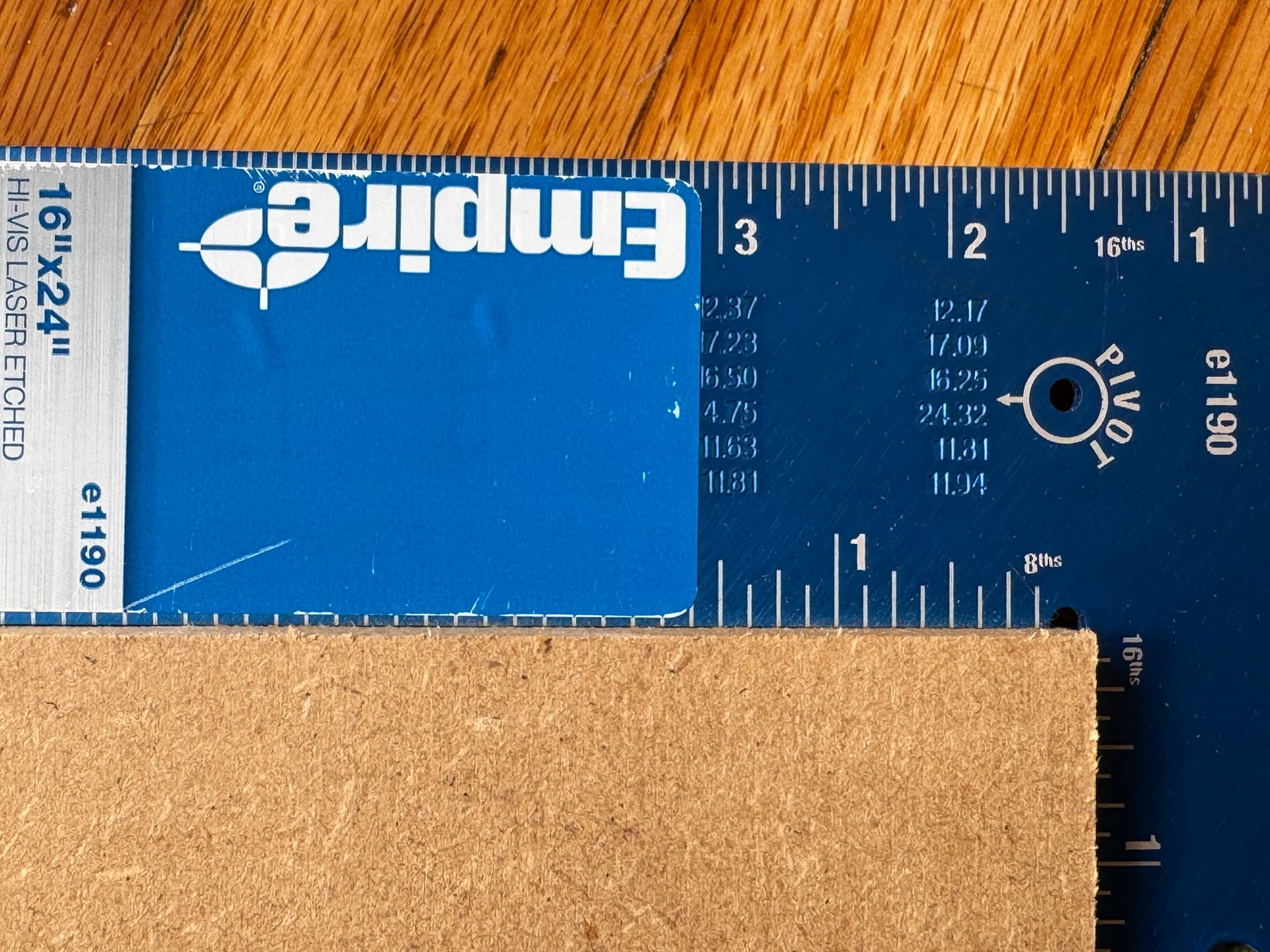
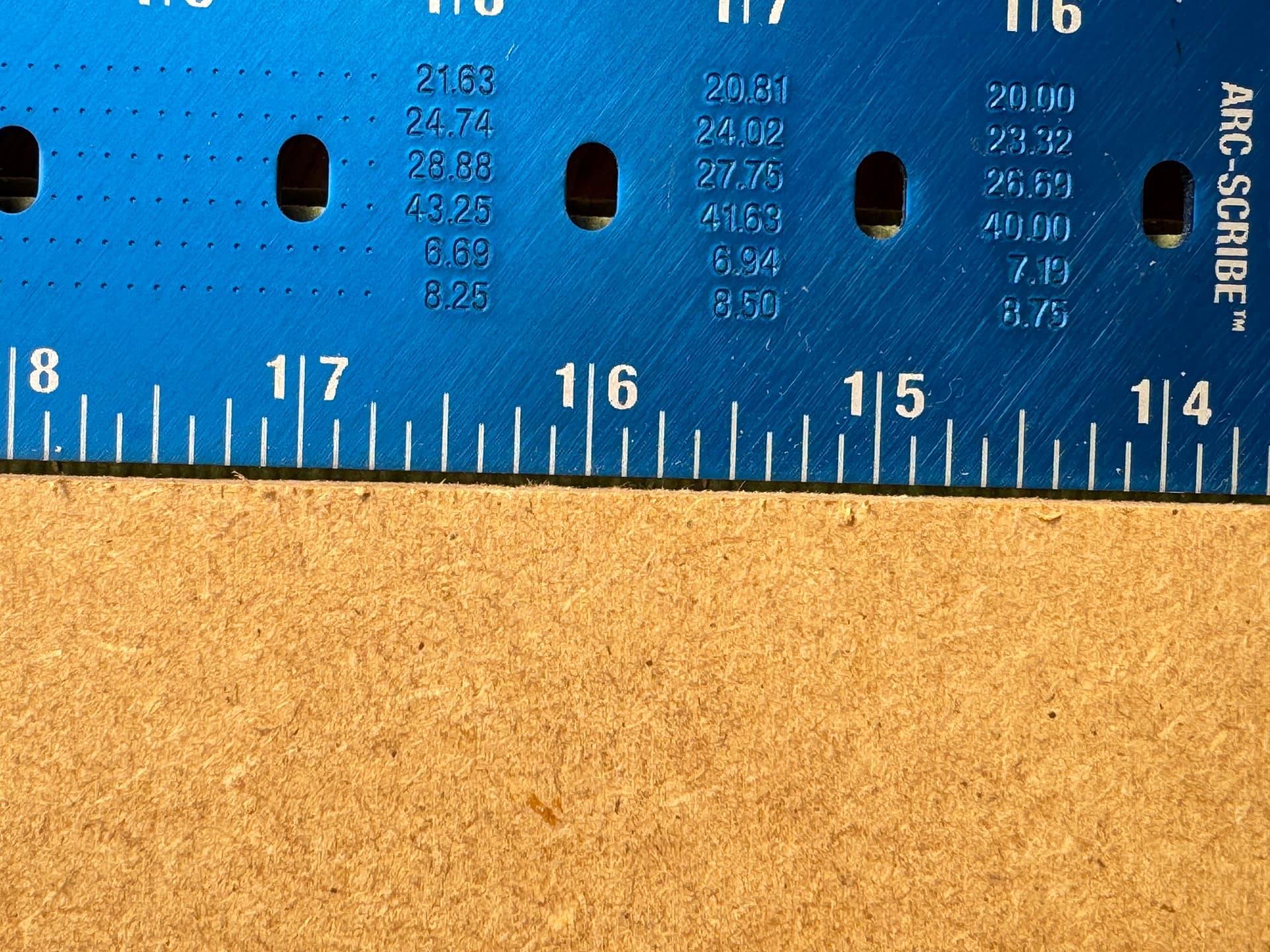
Then, cutting a 500 x 500 mm square contour all the way through, at 1mm depth per pass, (with 8 tabs), a thin piece of 1/2" MDF, using the #201 (1/4 straight bit), the square was “almost” square. Not quite.
At about 406 mm (16"), it was (1mm) “off” on two opposite sides. That’s definitely too much variance for what I want to do.
Am I going to get any closer than that with a Shapeoko 5 Pro?
Test it by marking a line from both sides — if not square, adjust into square:
That said, I’d recommend purchasing a good quality square which you can be confident will have been made square, and remain so — Lee Valley is one company which can be trusted to curate their selection:
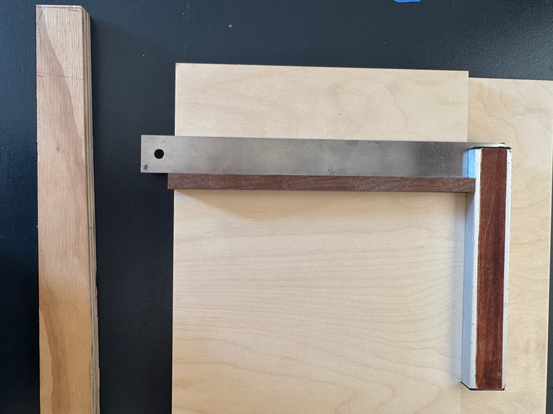
Do you have a table saw with an accurate fence? If so I would cut a test piece at least 24” long and 24” wide (just set fence, lock it down and cut all four sides without moving the fence). Set the board on the spoil board and place it to the far left against the inner left Y rail. Clamp it snug in place, put a V bit in the spindle and jog it along the edges to see what the results are. You should be able to get a solid reference off the Y rail to check you X axis with.
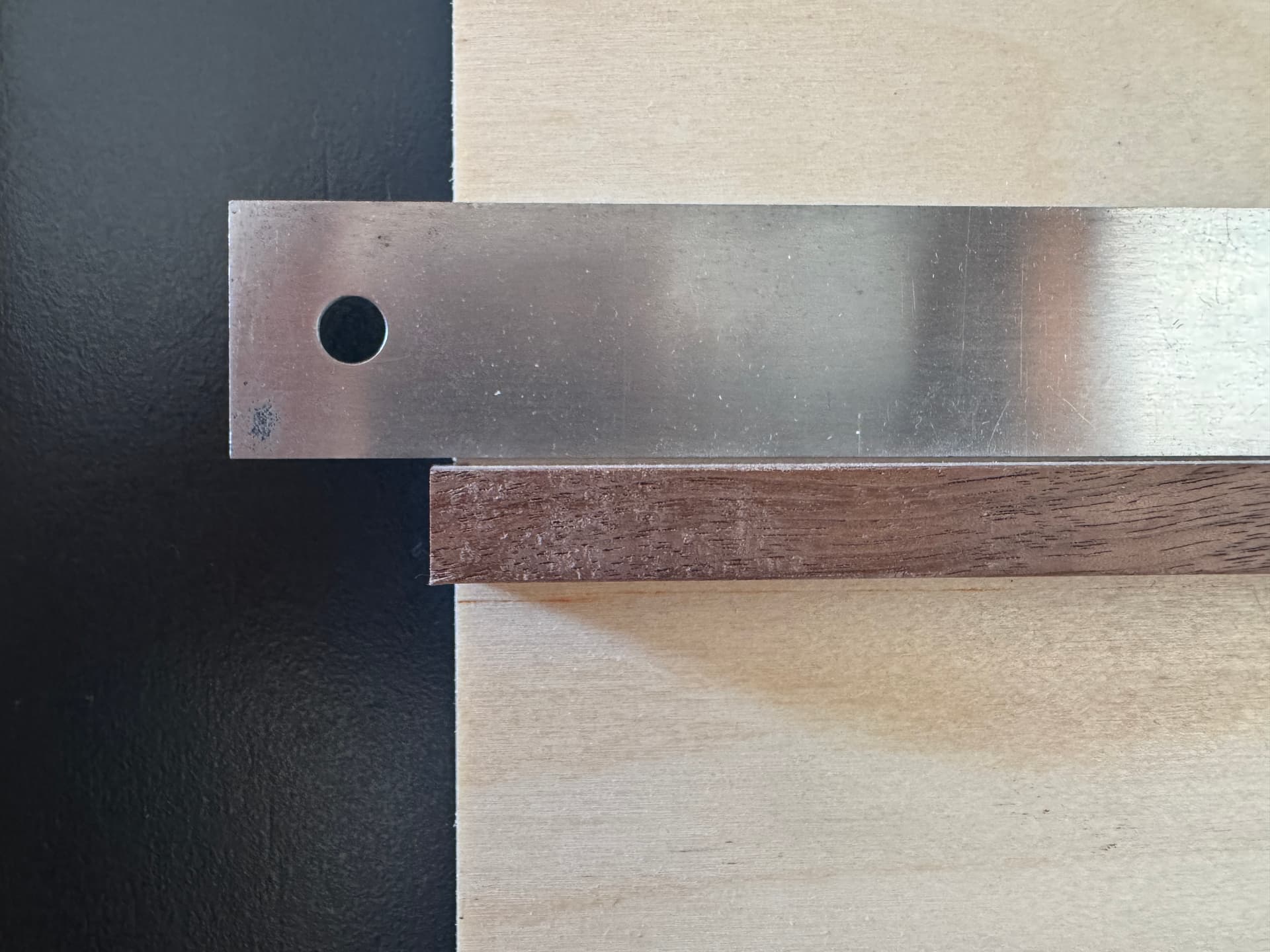
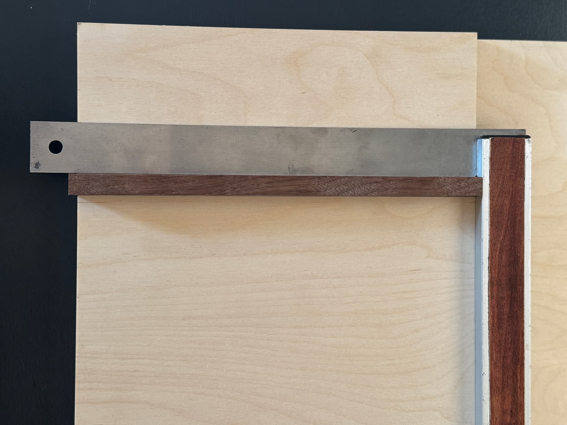
Are you cutting this Shooting Board out of one piece of MDF in one cut? does this include the dado for the fence you showing in the first two photos?
I believe the setup video is the only one from C3D, however the concept is the same. The sensors are set at the factory and normally should not have to be reset.
What we need you to do is gat a know reference to check square. Once you get the board clamped down you can use the other two squares you have to reference off the left Y rail just like the board is set. Select a point and jog along the X axis and see what you come up with.
The Shapeoko 5 Pro utilizes dual Y-axis homing to ensure that the gantry’s orientation relative to the rest of the frame is consistent between multiple power on/off cycles.
Although the perpendicularity of the X axis to the Y axis is related to how square you build the hybrid table, there is a degree of fine-adjustment that you can’t get just by tweaking on the frame and measuring corner to corner with a tape measure. Most people don’t need anything better than to build the machine with care, it’ll be square enough. But for ultimate accuracy, you’ll need to make micro-adjustments to the homing switches positions located at the rear of the Y-axis. Even though the Shapeoko uses good quality switches, each one has a small amount of variance in sensitivity from the factory and triggers at a slightly different threshold.
When you look at something you cut, and hold up a good quality square* as a reference, you can usually figure out if the left or right side of the gantry needs to move forward or back.
*Make sure you REALLY trust the square you’re using, otherwise you’ll end up chasing your own tail.
The Y-axis homing switches can be moved forward or backwards to essentially advance or retard the timing of when they trigger. This will tweak the angle the gantry settles at after homing. We don’t recommend loosening the hardware that directly holds the switches. Instead, the switches are mounted on a sliding carrier that moves them with more precision.
Loosen the button head screw on the side you want to adjust, make a small adjustment (about half a turn) on the socket head that faces the back of the machine to push or pull the switch forward or back, then re-tighten the button head which locks the position. Do a test cut, and see if it’s improved your gantry squareness. If it’s better, great. If it got worse, make a correction in the opposite direction.
If you need more help, reach out to support. I can also take some photos of what to adjust when I’m back in the shop.