Shapeoko XXL - final pass is stretched or offset

(Kinda irritated - as a newb I can only load one photo and two links - I’ll try to break my post up to explain…)

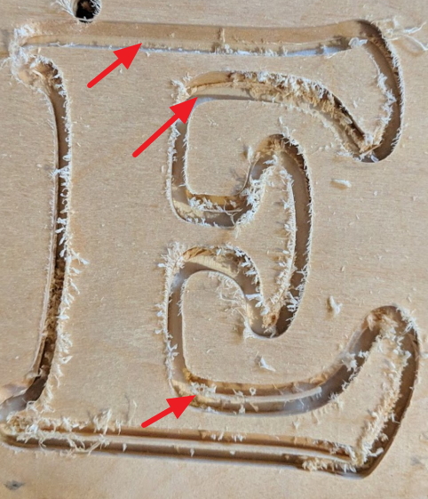
I’m getting a weird stretch/offset on the last pass of my cuts. I’ve seen this happen in both the X and Y axis now. The best I can explain it is the first 2 cuts are on the path as they should be. The final pass at full depth, it’s like the vector is stretched.

You can see in this pic there is a slight lip in the middle of the 5 and larger lip at the bottom. This is on the Y axis.

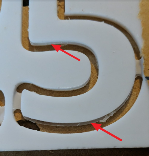
The width of the cut at the bottom is 0.1595". End mill was 0.125", so 0.0345" wider than it should be. The top of the 5 is 0.1275", 0.0025" off, seems within tolerance.

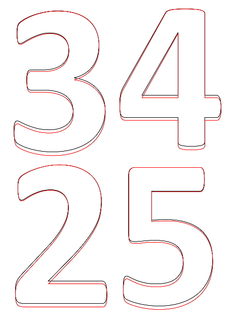
These are the two files, I’m using CC 464 and CM 513. This was created in CC.
House Numbers.c2d (772.4 KB)
House Numbers.nc (63.4 KB)

Here’s everything I can think that may be pertinent:

  • Shapeoko XXL with Z+, ordered in March 2020
  • It is square and level, checked and quadruple checked
  • Checked the belt tension, all seems good
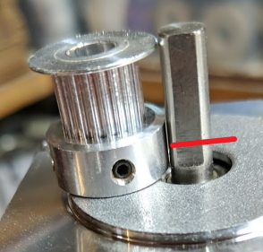
  • Checked the cogs on each motor, all the grub screws are tight and aligned to the flat
  • Z axis is trammed both left/right and front/back
  • I’m using a Bitsetter
  • I’m using a touch probe

I’ll note that when I first noticed this on a different job I found the X axis had slipped (don’t thnk that was the cause though) - the mounting on the Z+ causes the gear to be pushed back on the shaft flush to the motor, the grub screw did not mate to the flat. I filed the shaft down and the grub screw is now on the flat and it is tight.

So now I’m out of ideas. Problem with the controller board? Bad USB cable? Bad motor? Software issue? Firmware? Operator error?

I should also note I switched to a newer computer for the acrylic numbers file for both the design and cut with a fresh load of CC and CM.

This is my first personal CNC, but plenty of experience on big Multicams and similar. Apologies for the long first post, any help is appreciated!

(Apologies for the multiple posts)

This is what I think may be happening. The black line is the actual cut and what is used for the first 2 passes. The red line is what is getting cut on the final pass, like the image got stretched. Each shape was off the same amount in the Y direction, it’s not like the entire file stretched together, the 4 is the same measurements off as the 5.

Here’s a comparison of the code for the 3 passes for the #2 and #5, nothing unusual, all X and Y coordinates match for all 3 passes of both.
Numbers gcode analysis.zip (22.9 KB)

(Part 3…)

Here a photo from the first job I found this on - this happened on the X axis. The left of the E is the correct cut with a 0.25" EM. You can see where the first 2 passes cut fine and the last pass shifted dramatically to the right, by more than a quarter inch at the bottom of the E. This happened both on contour cuts and pocket cuts - both were off on the final pass. This was an SVG imported to CC. The acrylic in the first post was created in CC.

Slotting is hard.

Add geometry and cut as a pocket down to at least tab depth:

And check the machine mechanically: https://wiki.shapeoko.com/index.php/FAQ#Mechanical

*(final post, sorry… :slight_smile:)

The red line in the photo is where the flat ended originally. This is when I found the X axis cog did not mate with flat due to the way it is mounted on the Z+. I filed it flat from the red line down.
Image 006

Last thing I’ll add to this is I made a threaded spoil board this weekend. 184 holes with shoulders. All look correct.

Thanks for help/ideas!

1 Like

Thanks for the idea Will. I’ll review the mechanics again. Been over them in excruciating detail. Every eccentric nut, every belt, every motor, every bolt.

I guess I don’t understand the slotting issue. Maybe on some really deep cuts. This is 3mm acrylic, shouldn’t the machine be able to handle 3 passes and cuton target? Also, on the wood file it happened on the pocket cuts and the contour cuts, they were both off on the final pass.

If it’s always the last pass I’d also look at how you do work holding…

3 Likes

I thought that too - both jobs were very secure. The wood job was screwed directly to the spoilboard (before I added threaded mounts). The acrylic was mounted with DS tape and taped on all 4 sides. Confident it didn’t move. What’s weird is each # was cut one at a time. The first two passes were lined up, the final pass was off. Movement would make sense if it cut the first pass for all 4, then the second, then it slipped on the 3rd pass and cut all four. This cut the #3, first, second, third pass was off, then moved to #4, first, second third pass was off - etc.

Double sided tape is pretty spongy. As you cut through the main stock on your last pass, you allow for movement… Even if everything still seems secure. Try blue tape and CA glue.

2 Likes

Since your first couple of passes are good it is most likely work holding. If you had a mechanical problem it would show up on every pass. The #102 bit is an up cut bit. The cutting forces try to lift the chips up but it also lifts the workpiece up and out sometimes. Since this is acrylic it is slippery. Perhaps you have a down cut bit which would force the work down and the top edge would be cleaner. Although on close inspection this seems like a lot of movement from the street with the numbers on your house no one will ever know. You could decrease your depth of cut and make more passes so that your last pass is very thin. Try to anchor your project down maybe with a holding jig that some use to carve v carving on top of boxes.


If you use a holding jig make sure you make one or more holes in the bottom to extract your project when you are done. If the holding jig is tight extracting is impossible without a way to apply upward pressure. I learned that lesson on this very project and now make one or more holes in holding jigs to help get the project out.

2 Likes

Although it probably is holding up well, I’ve had a few cases where the first set of passes held up wonderfully - but during these passes, the piece was warming up to a temperature where the adhesive on the double-sided tape lost integrity and then slipped.

1 Like

@gerry, @neilferreri, @gdon_2003, @fenrus - thanks for the ideas. I do appreciate what you’re saying and agree on the importance of stock hold-down and worked with acrylic (past life in the sign industry) so familiar with the properties. The wood sign (letter E above) was solidly screwed to the table.

Here’s what I find weird in this. Each shape it does all passes to final depth then moves to the next shape. Really odd to watch the first upper passes go perfectly, then watch (and hear) the final pass at full depth “grow” in only 1 direction, like the image above with black and red lines. Then it moves to the next number and the same thing. It’s what happened on the wood sign as well, each path it would do the upper pass on track, then the final pass at depth it would “grow” in one direction.

So, I went out this morning, new file, new piece of wood firmly bolted to the table, micrometer ready, and ran a test. It all ran perfectly. Of course :joy:.

No more time to mess with it today, I’ll be back it this evening to see if I can recreate the conditions. Not dismissing the stock slipping (it’s a solid maybe…), but I’ve seen that plenty and end up with the rest of the cuts skewed. This was really odd to watch. I’ll see if I can get video next time.

Yep! A little hit hit on the sander and those puppies got glued to the mailbox - LOL.

also if you want to reduce forces AND you have the space for in the design, you can try to do a pocket instead of a “slotting” cut. just make an outset (using offset tool in CC if you use that) that’s 2x the width of your cutter and pocket that.

During slotting you have 100% of the cutter surface engaged, during slotting it’s much less (typically 50%) so deflection of the bit and other force related deviations all go waaaay down.

1 Like

I figured it out after a lot of testing over the weekend. The left side pulley on the X axis motor was loose. Hard to diagnose since both set screws felt tight. Found it by accident when I was working on it and noticed the movement on the left side when the machine was powered on. Right side was locked solid, left side had play. Backed the screw out and tightened again, now it’s solid and cuts since have all been on track. Maybe something on the threads of the set screw keeping it from mating all the way. I’ll probably tiny drop a dot of Loctite Blue on the set screws this weekend.

2 Likes

Instead of putting locktite on your set screws you might want to consider replacing them with cap screws. The cap screw has a larger hole in which to tighten. If you have to replace a motor or other maintenance with the locktite you could strip the tiny set screws and do a more extensive repair. Even the semi-permanent or vibratite type locktite is hard to remove on such tiny screws. The specs for the metric set screws are on the Carbide3d sites and since there is not a space problem would highly recommend replacing the tiny set screws with a cap screw.

1 Like

Good call - I’ll go that route - can get a little more torque on those without the need for loctite.

This topic was automatically closed 30 days after the last reply. New replies are no longer allowed.