Simple Questions Asked

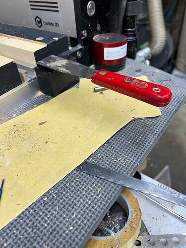
I thought I had tooling of my machine figured out and hadn’t had a problem putting tools in the machine, touching off, and then running, so I thought. Well, this morning I started the machine up, initialized it and when it came to the front to touch off on the bit setter at the front right of the machine, I put in the surfacing bit I have. Then the machine touched off the setter and then went to standby mode. I checked my program in CCP and made sure that I had a few added adjustments to accommodate for the smaller part being surfaced. I had the material locked down and moved the tool over to find X and Y zero. Once that was completed I went ahead and touched off the top of the material to set my Z zero.

The program was then loaded into CM and checked for material height to make sure I was running the right material height. Then I started the program and the gantry came back to tool change location and asked for the tool in the spindle. I pressed ok to let the machine go to the bit setter and touch off. Then the machine started the program. It moved over to the start of my surfacing front left side, came down and crashed hard into the holder ripping much of the holders material off, twisting the holder and locking the spindle in spin. I hit the red button.

I turned the machine back on, and re-initialized the machine. I checked the tool and was lucky it was fine. I checked the holder and it was destroyed. The part, luckily, didn’t move. When the machine did another tool check during initialization, it had the same tool in it. When I checked the height of where the machine thought was Z zero, it showed that it thought Z zero was almost .500" deeper then the material. So, I moved the tool back to the height of the material and touched off again. I noted the height from the Z zero on the machine and the location I was originally trying for in the first place. I set Z zero again and loaded the program and started it again. This time I moved the tool of the surfacing off further from the part so it wouldn’t crash down into the holder.

This time the tool came down and was still further down to -.148" rather then the -.020" that I was wanting to cut. I stopped the program. Reset Z zero to the material again, which was off again, and then started the program again. This time it went over and only cut down -.020" like it was supposed to.

So, what the hell was I doing wrong to make this tool come crashing down into my holder like a bad stepchild? Where am I going wrong on setting my Z zero? If the machine has an understanding where the top of the table is and the bit setter is set to understand where the tool end is in comparison to the spindle collet, then why does it have to mess up so much on dealing with Z zero? I run a hundred thousand dollar CNC and when I touch off the tool to the part, the machine knows exactly where the Z zero is. Then when I run the program, I don’t have to worry about the machine Z zero and the tool coming crashing into the part.

So, if I touch off the material on my S5Pro, then it should know where my Z zero is to the machine because the machine already knows where Z home is and where Z zero is to that home. So, if I have the program setup saying the material is .625 thick, the Z zero was touched off to the part, and Z home knows the distance between the two, then why does the machine confuse itself when it touches off the tool to the bit setter? It really is as if the bit setter is really the trouble here. I don’t never use a bit setter on any of my big CNC machines to know where the Z home and Z zero are in comparison.

My question also is how do I actually set my tool in Z zero and make it stay there? When do I set material zero? Or is it unnecessary when using the bit setter? Or is that part of the machine that is attached to the front right of the machine not the bit setter and actually something else? If I load a program, does material Z zero have to be retouched off? If the machine is initialized at startup, does resetting Z zero have to be done after the program is loaded or before? I am a bit lost as to why my machine crashed itself into the material holder and how that setting Z zero two different ways it still almost crashed once and did crash one other time.
Which version of Carbide Motion are you using?

Please see:

https://my.carbide3d.com/gswso/06/

How are you setting origin relative to the stock?

Where is the origin set in your file? See:

https://my.carbide3d.com/gswcc/02/

When you initialize the machine it knows where the origin (right, back top) is and the extents of the machine — though that is only limited when jogging, and check for when loading a file, see:

https://carbide3d.com/blog/carbide-motion-bounds-checking/

When are you changing tools?

1 Like

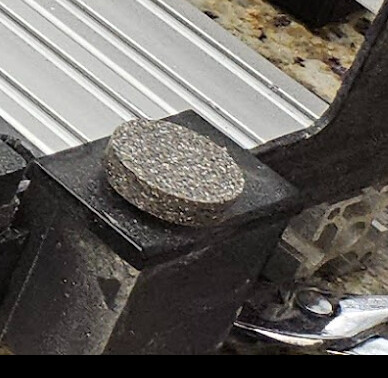
Which surfacing bit are you using? Most of them like the Whiteside bit I use does not cut all the way across the center. If you use the bit setter the tool will be set to an incorrect length because the bit setter button can go between the cutting edges of the tool and “measure” the tool incorrectly. I have added a button to my bit setter that is larger than the OD of my surfacing bit so I can be confident the bit setter measures the cutting edges. Your first offset error seems to be too large but the second is right in the neighborhood of measuring to the center of the holder and not a cutting surface. Have you seen this issue with a standard end mill?

1 Like

I’m using Carbide Motion Build 618. I don’t even know how to update the program without being attached to the machine. But the other issue is that I don’t have internet at my shop, so connecting to my machine and being on the internet is not even possible.

Can you bring your device to the internet?

After download hook back up to your machine and follow new machine setup

I should have looked over the rest of your post and questions before answering the first question. I am setting my my X and Y zeroes at the upper left corner. I have a 90 degree corner permanently attached to my table to continue to hold X and Y zero to this corner. This way I can set all of my program designs to that location and quick connect them to my table and not have to reset X and Y zero all the time. I wanted to change it to the front right, but that isn’t even an option in the programming.

The files are also set in the same location. Each one are programmed with X and Y at top left. I have tool changes only when they are required, unless I have a small endmill in my spindle when I go to shut the machine down for the day. I remove the endmill because when I shut the machine down, the spindle slowly drops itself until it comes to rest on top of the table. I have a foam block in the way to stop it from going all the way to the table, but just the weight of the Z housing and spindle could be enough to break off the endmill when coming to rest on the table.

So, when I initialize the machine upon turning it on, the spindle is without a tool. Once the gantry moves forward to the front, the program tells me to install a tool into the spindle. Once the tool is installed that I am going to start with, the machine measures at the bit setter. That is when I usually will touch off the endmill to the material. As my understanding, that would seem the more likely time to touch off the material right after initialization and the machine knows where the tip of the tool is in retrospect of the Z home. Then when I touch off of the material to set Z zero to the material, the machine should know all points of references in order to run the program safely. But that didn’t happen this last time. The machine thought the material was .5" lower and crashed hard into the holder.

I will now go and look at the post you have tagged into your response and see what is there for me to see. I don’t get to run my machine like many other people do. Even the weekend warriors sometimes get to run their machines more then me. I also have a trip coming up next month that will have me gone for 6 weeks. Will be some time in there while I am gone to use my computer to design a few more ideas and then wait until I get back to test.

I come home and bring my computer with me. What I am typing on right now is the very computer I use at the shop. I dont fully like it but have to deal with it this way for now. Besides, once I buy another controller computer I will have to invest in Carbide Create Pro again in order to have the program to be able to check programs there on the spot, or to make changes to the program if I have something a bit off when I am at the shop. In the meantime, my laptop comes with me to the shop to deal with anything in both programs.

I am using a 1" surfacing bit that hits right in the middle of the tool. It may miss the tips of the cutters a little bit but not .5" or even .145". The worst it could be off is possibly .03" and that really isn’t a concern when I am doing the first side of a two sided surfacing.

I havent had this issue but one other time when I was running a big v carving project that ended up cutting a little deeper then expected, but that was only going about .025 deeper then I wanted it to go. I thought that maybe the issue was more the uneven surface of the material. So, that is the reason for the surfacing program that I made to combat this uneven surface issue. I have ran the program before on the panel I posted in the thread, “What did you create on your Shapeoko today.”

None of my other projects had the issue of a tool driving too deep into the material because of zeroing the tool on the material.

I just updated my Carbide Motion to Build 635. My old Build was 618 and a bit behind the updates that have been added over the time I got my machine until now. I have only updated CM this one time. I didn’t know we even had this many updates to CM. This fixes a few of the things that I was not liking about the slow movement of the z axis to the bit setter, and even the long process time of touching off a tool to bit setter. Setting Z zero will also be a breeze now. No more worries about the machine possibly crashing like it did before.

One other question for my CM icon on the main screen of my computer. There is a little red #6 at the bottom right of the icon. Does anybody knew what the means? I thought maybe it was an update thing and now that I have updated CM, the number is still there.

Number six references the build 6xx

1 Like

The Whiteside surfacing bit I use has an opening in the center large enough to fit the button of the Bitsetter. I think the cutting edges would crash into the Bitsetter before measuring inaccurately if I did not add a larger target.

1 Like

I see what you mean. The tool you use is a bit larger and may actually cause issues touching off. The diameter of my bit isn’t much bigger then the bit setter. The little difference doesn’t matter to me if I’m just surfacing material, but it would matter to me if I were cutting some fine details and needed the depth of cut to be point on. If you add a little plate on the bit setter, wouldn’t that mean you also have to adjust for the thickness of that extra thickness of the button you have added?

Not if you keep the plate on the bitsetter. It’s a relative measurement, so as long as every tool touches off at the same height…

3 Likes

I wiped the top off mine wile surfacing and placed a magnet on it… Just trow this on when I surface to help with the size. No you do not have to recalc the depth

2 Likes

I keep the button on all the time so it does not matter at all.
image

3 Likes

My issue now is just getting over to my machine and actually rerunning the setup for the new Build update. I have been working on building a cabinet and countertop for a new build in and install of a sink, new plumbing, and new drain lines. I’m remodeling one of our rentals and am installing a kitchenette with a new gas stove, new frig, and a new sink complete install.

I decided that I had so much wood, there was no need to go try to buy a cabinet that might work. Instead I decided to build my own with red oak face, and red oak countertop with live front edge. I will need to go over and address the machine update/setup because I want to surface the countertop boards on the S5Pro. My planer would work as well, but it is raining here and has been for the past 2 days and I don’t have a dust collection system in my shop just yet. So, I have to open my big door and let the dust fly out the door. Raining and moisture are not my friends right now.

I decided that a good surfacing program would solve the planing issue and make sure each board is exactly the same thickness, also, they are flat as well would love to go ahead and edge the boards, glue them up, and then surface them. Just don’t have enough clamps long enough to do all of this. Maybe I need to stop procrastinating buying my clamps, or making the wooden ones for longer projects like this.

I purchased an STL file and it was downloaded into my computer. I can see it there. I cant bring it up in Carbide Create Pro. It will also not come up in Inkscape. Seems none of these programs support an stl file, so they wont bring them up at all. Does anyone know how to get around this problem and allow me to be able to open these files? Or would I have to convert the file to a svg file and if so, how do I do that? I wanted to buy a file that I wouldn’t be spending a lot of money on so I could figure this stuff out before I invest more money on anything else.

Can anyone help me figure out how to open or convert these files?

STLs are not directly opened, instead they are imported as a 3D model component based on selected geometry (which provides a centerpoint for the XY positioning).

Please see:

https://my.carbide3d.com/gswccpro/07/

and

and

1 Like

Thanks. I will look into all of this to see what I can figure out. I didn’t want to be purchasing files that I couldn’t use. Let me dig into your suggestions here and see what I can come up with and hopefully I can begin carving these designs soon.

I bought the Pro version of Carbide Create and had available the 3D creating, but I stayed away from it because I didn’t understand it yet. Also I still had more learning to do on the other stuff in regular designing. Now I want to get into some of these 3D designs and the stl file imports. I have a lot still to learn on CCPro and haven’t even tried to open Inkscape to try designing in there. But thanks to those that were ahead of me asking the questions I have asked, they have paved the way with all the explanations already getting done. Thanks Will for all of your help here.

1 Like