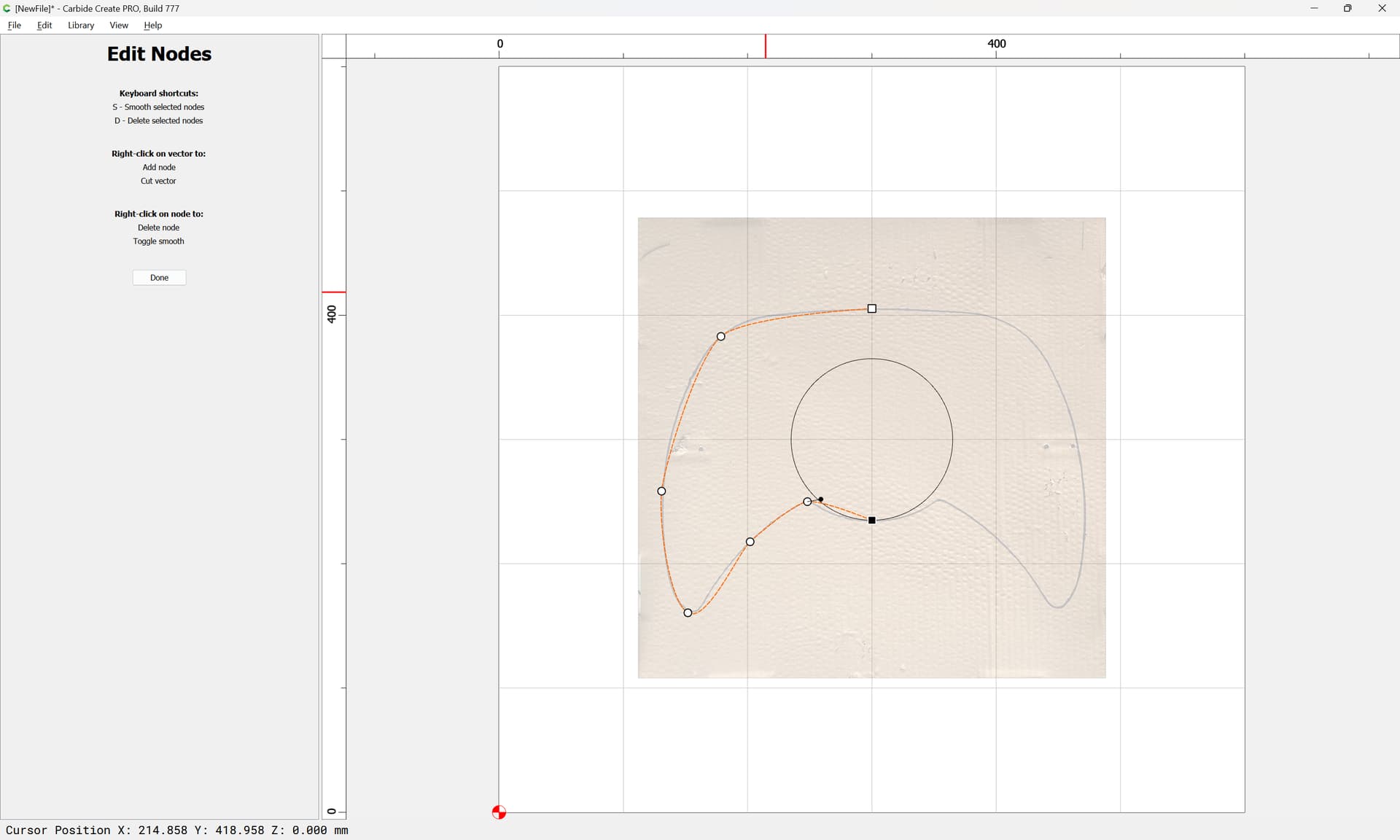
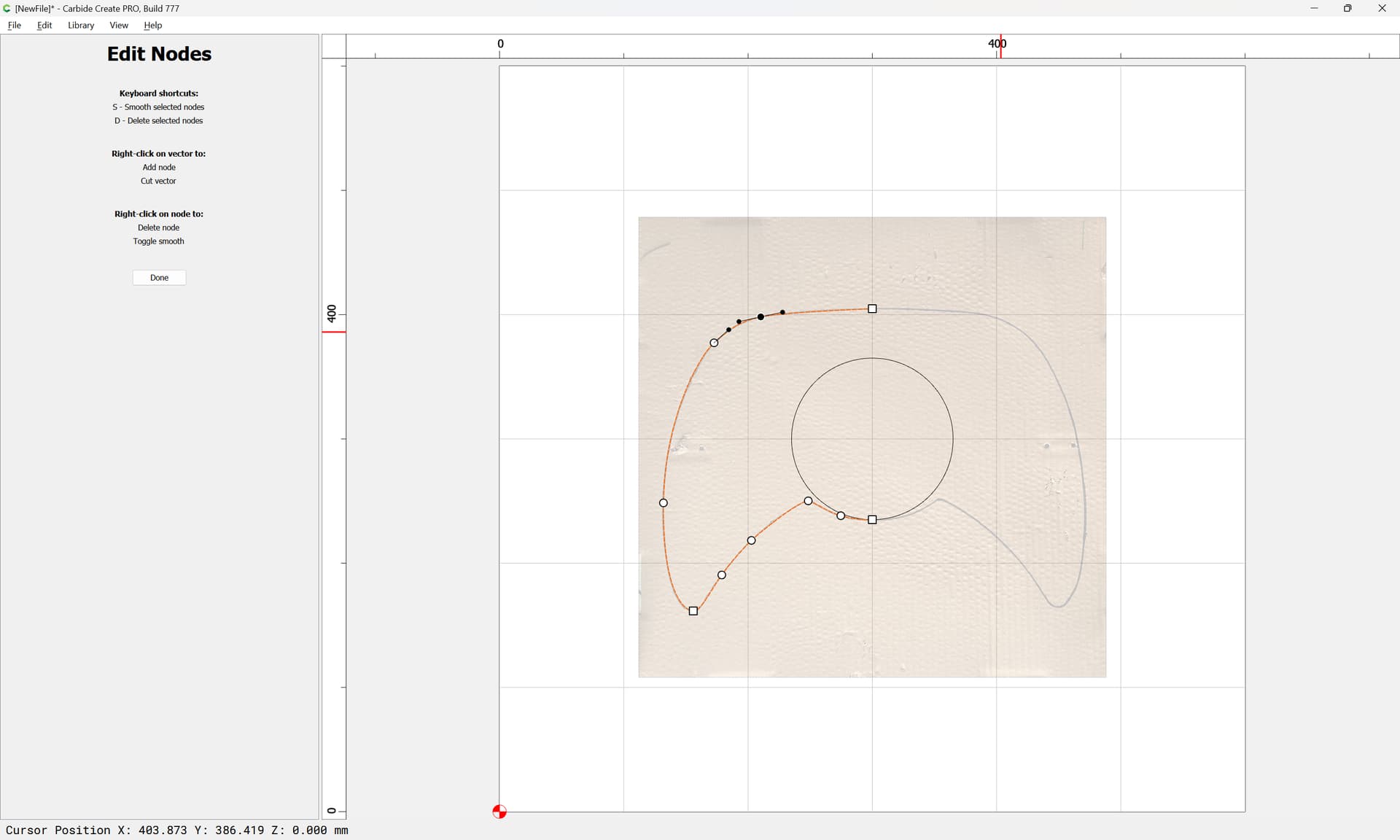
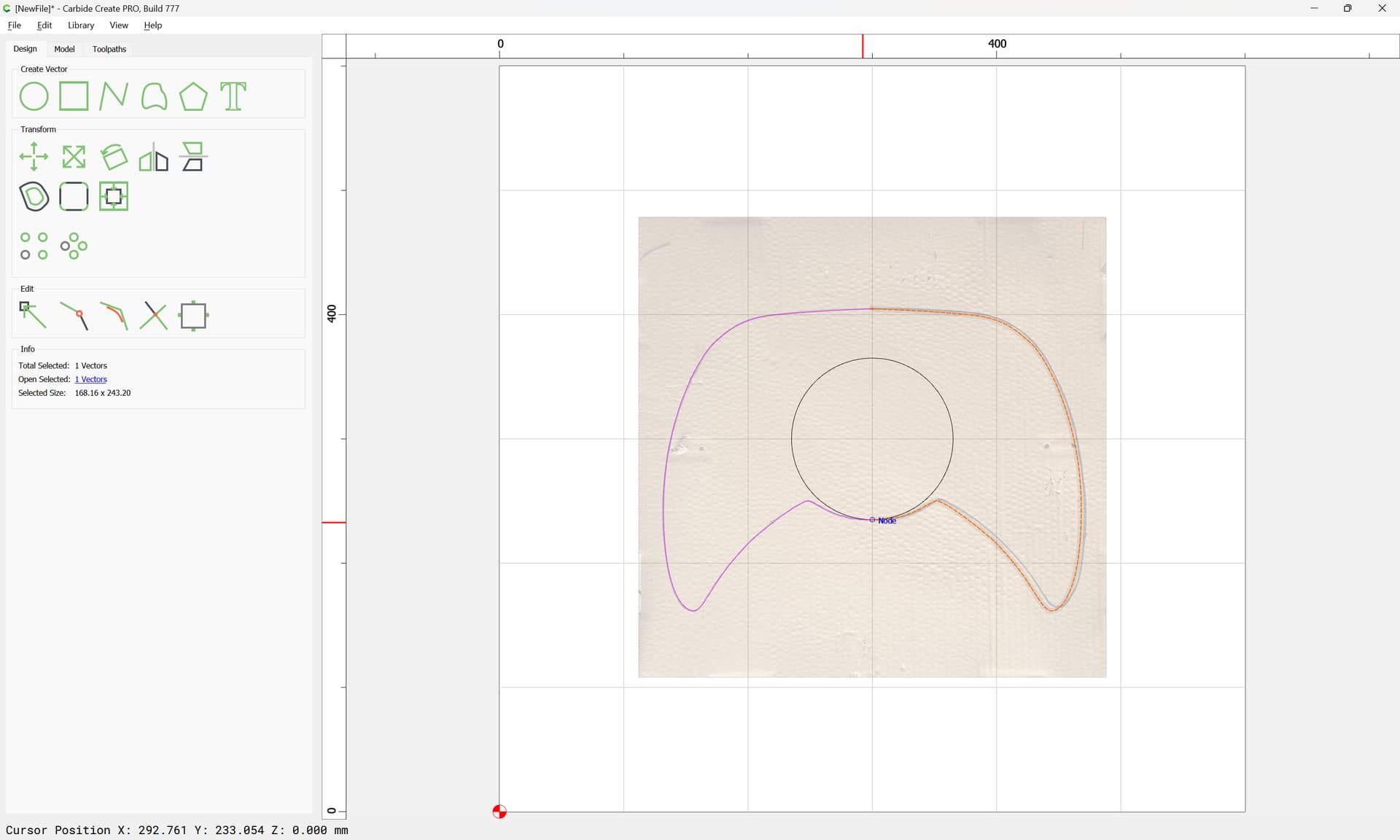
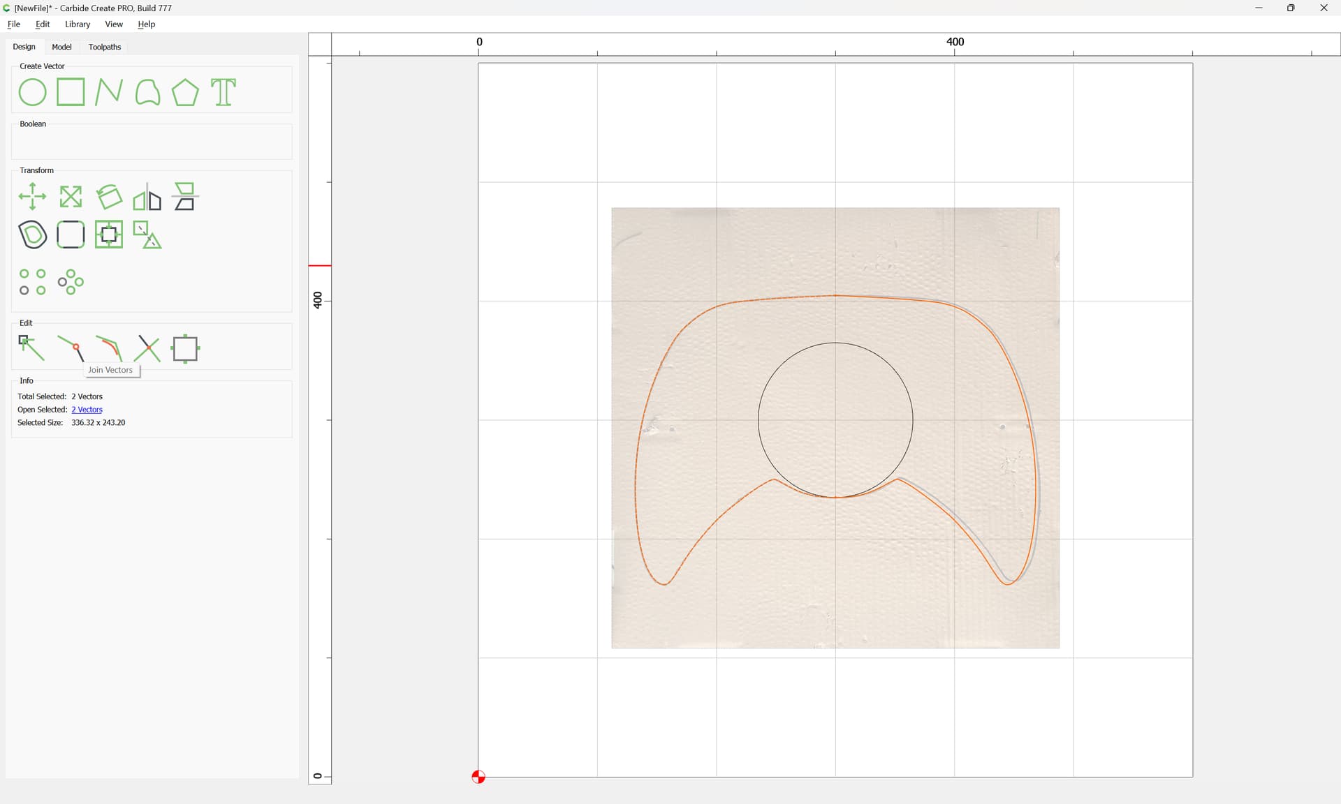
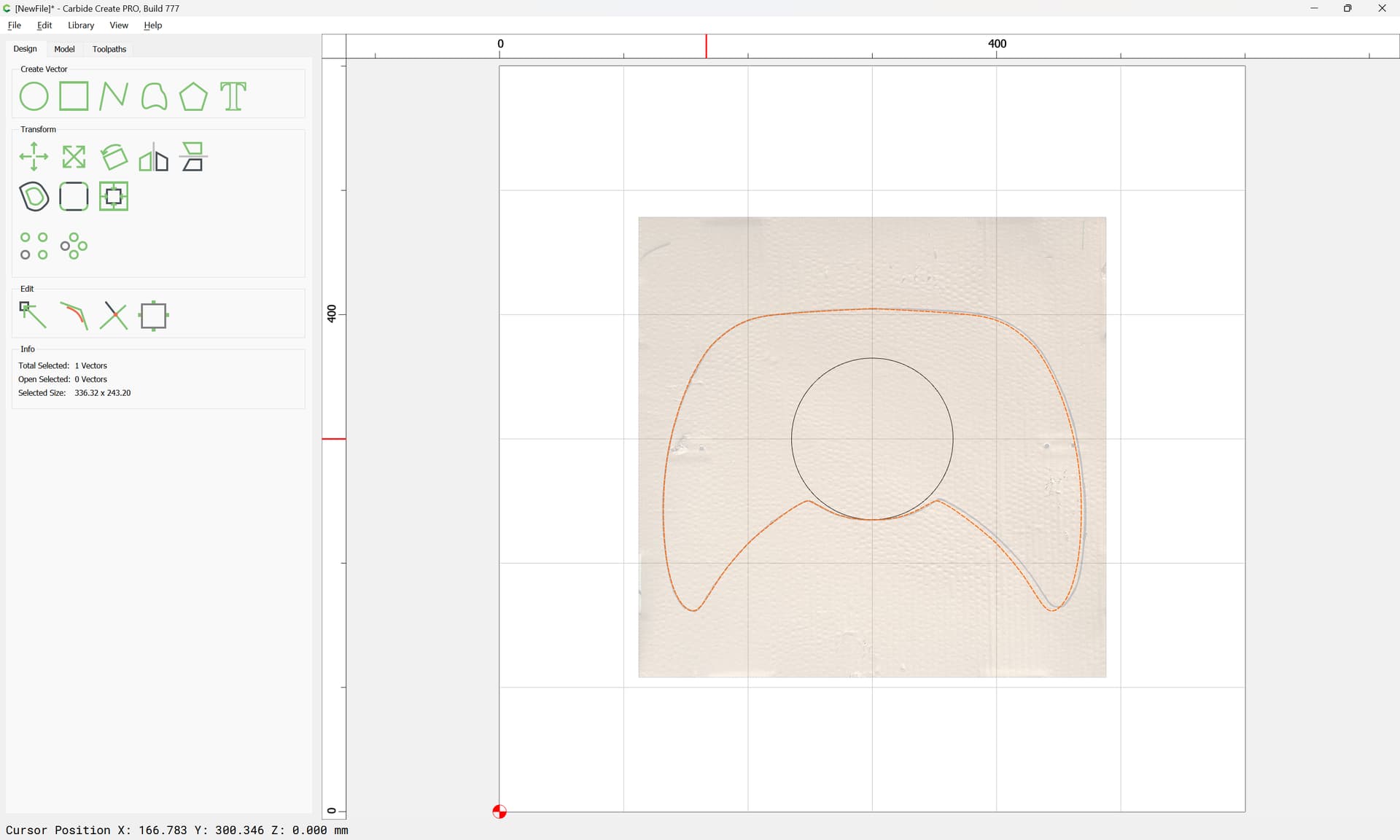
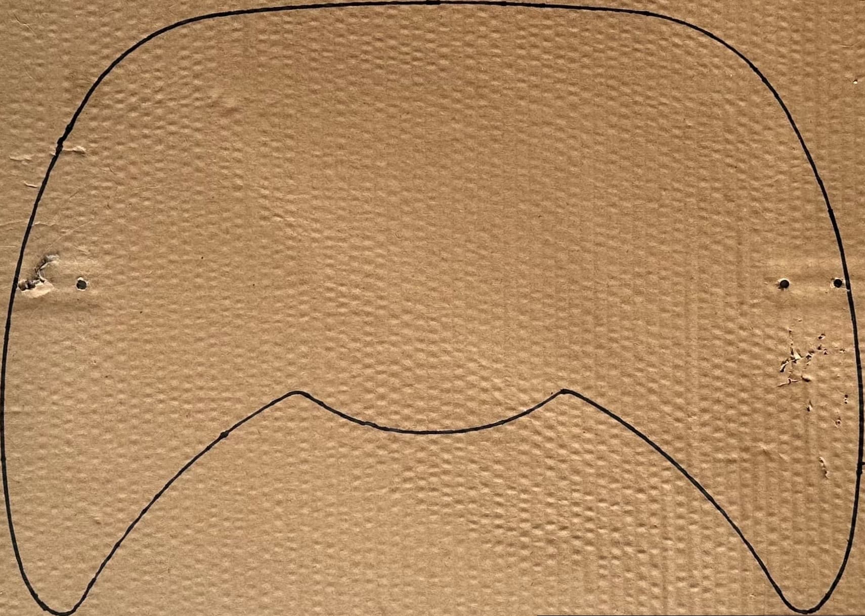
it gets really hard to get designs right for me @WillAdams I tried with other panels and they came out great but I still get a small measurement off. How could I make this panel with this much curves and have it right. I drew the outline for this one since it wasn’t laying flat
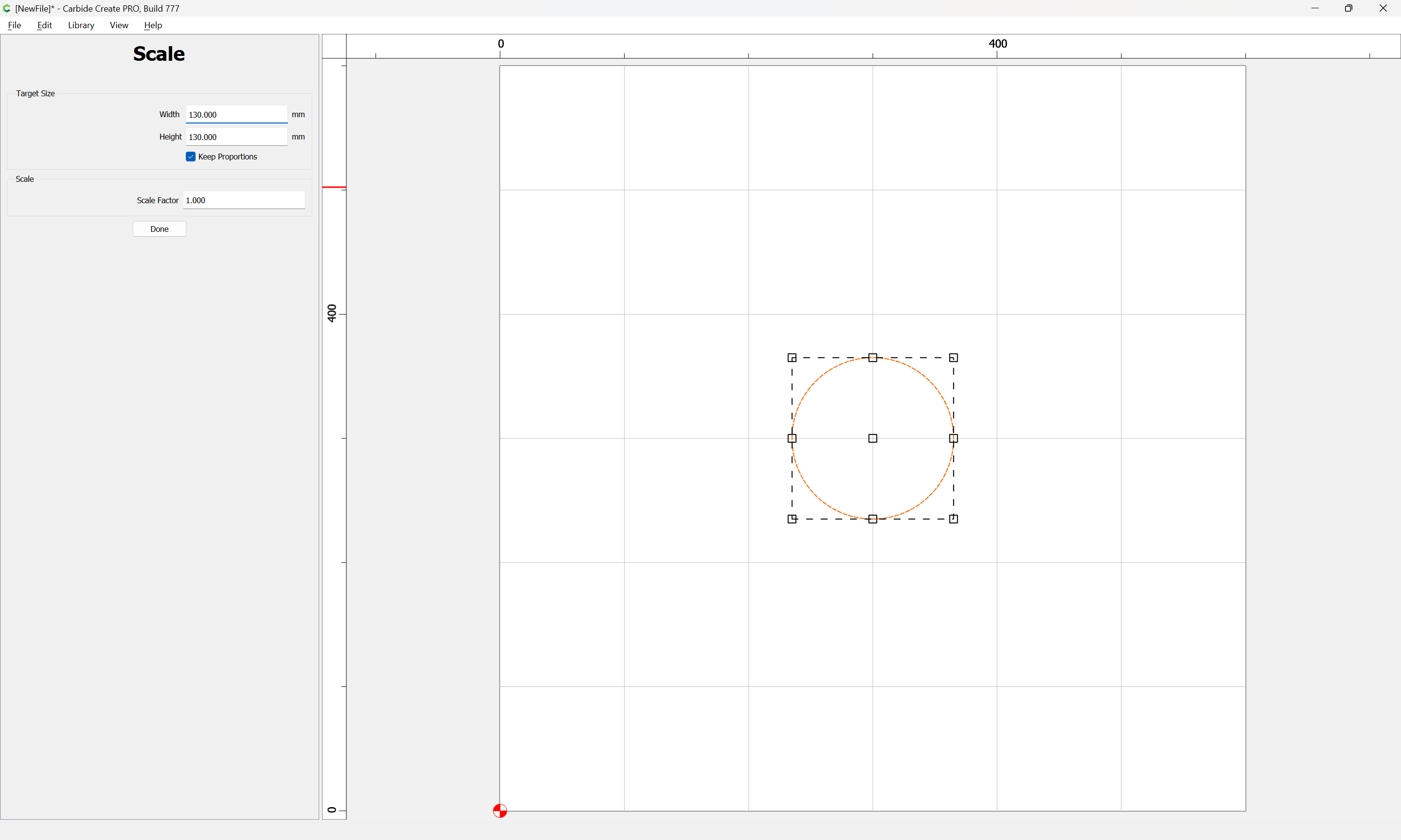
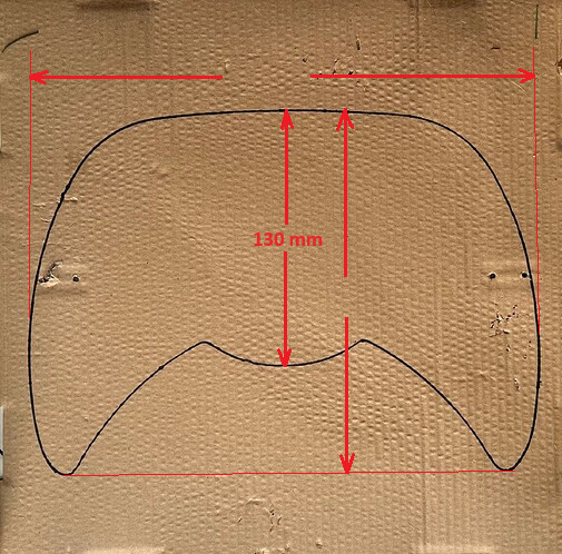
I would start by using a few more dimensions. I assume your 130mm is the measurement I drew?
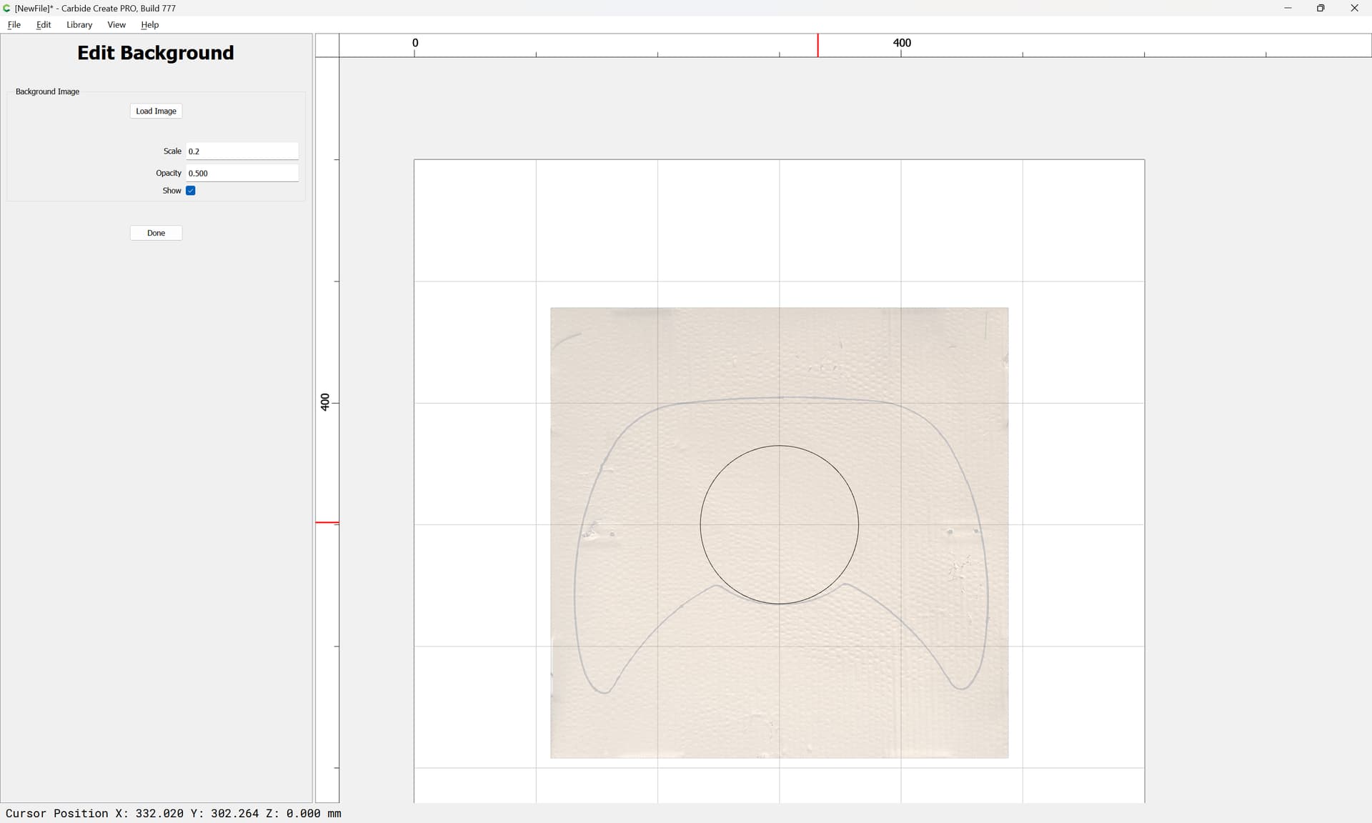
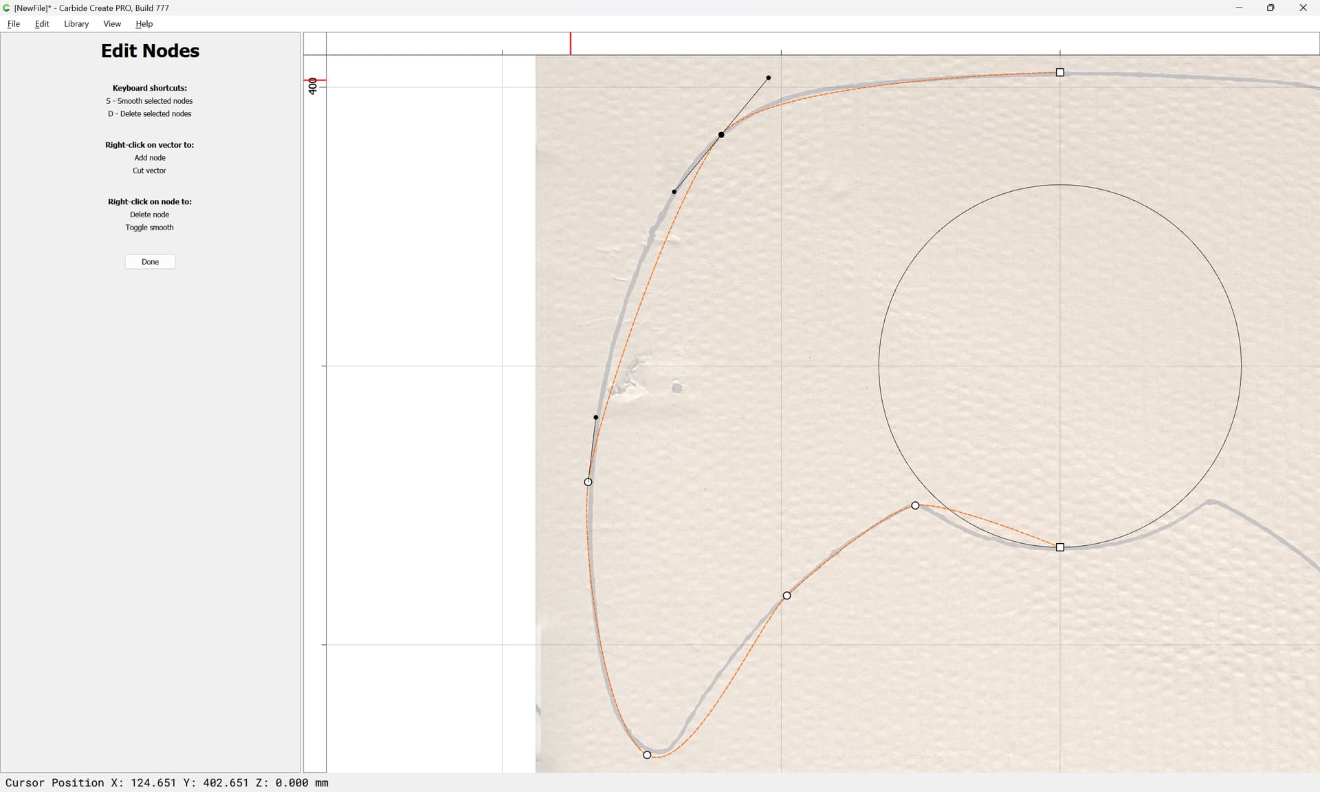
Taking a picture of a trace will not be perfect. Your best bet is to make sure the camera lens is as close as possible to the centerline, perpendicular to the paper, and as far away from the paper as you can get it & still get a decent picture. That combined with the additional dimensions will get it a lot closer.
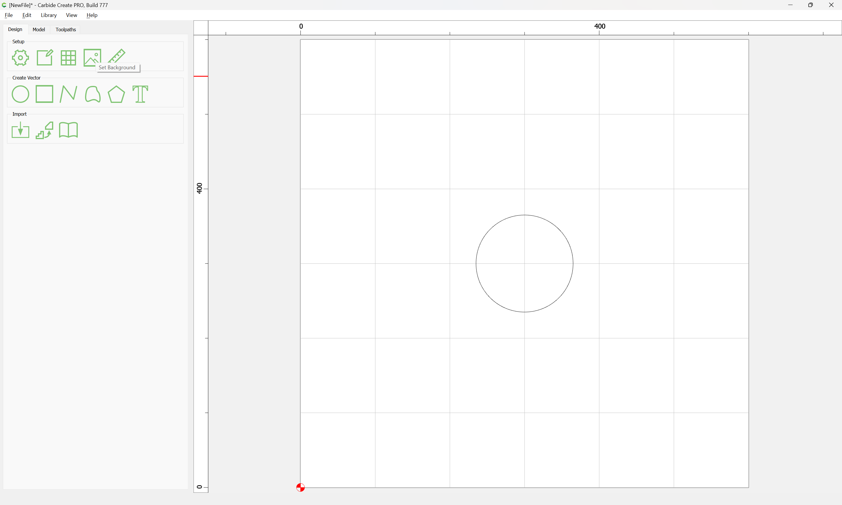
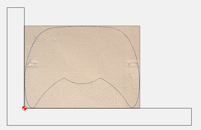
With the dimensions above, you can create a frame for the image to know you have it aligned as good as possible.
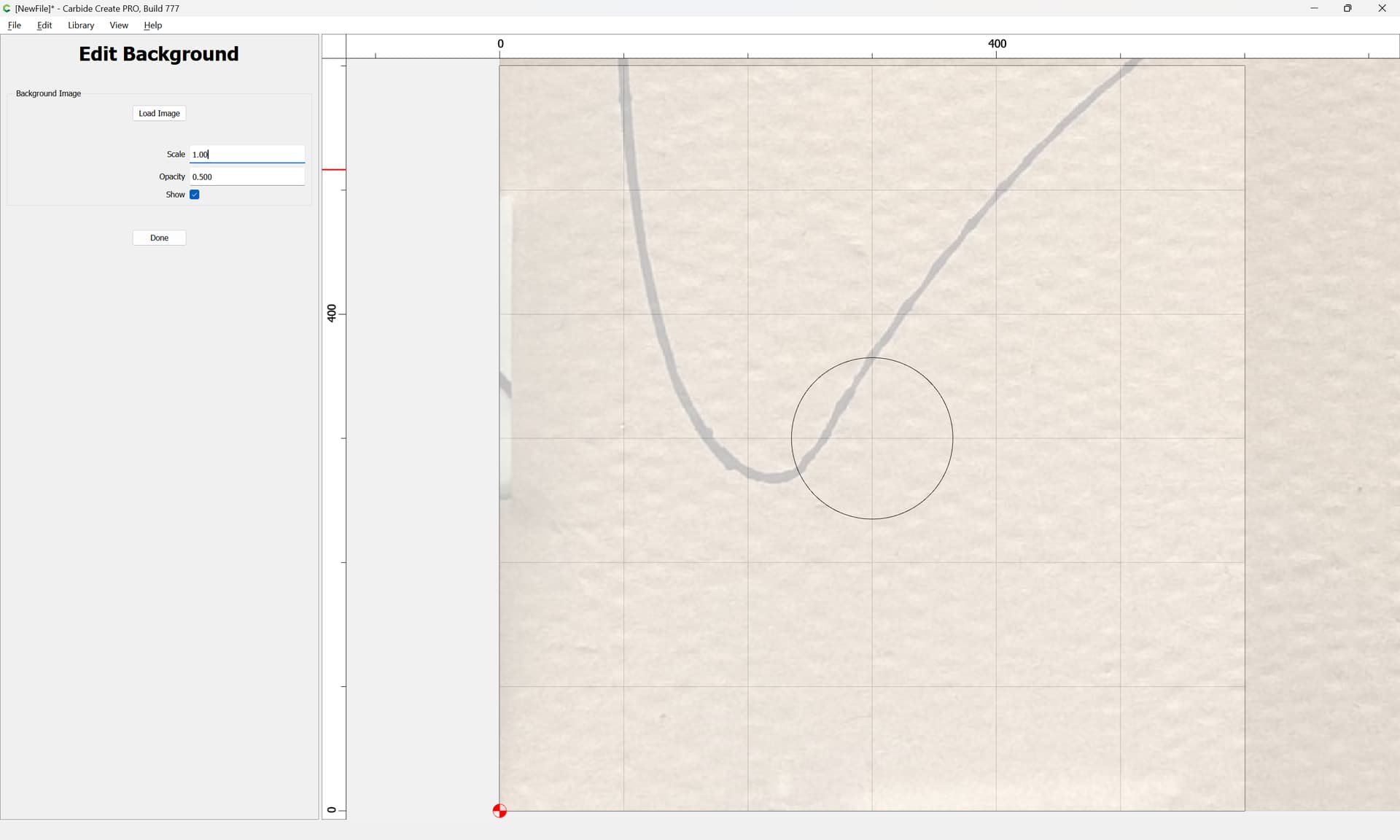
The next thing would be to edit the picture & get it square…
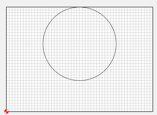
Thanks will for showing how to do this in CC. Getting curves right also needs experience and eye-training. These 3rd degree Bezier-curves are great for drawing, but they are not ideal for all shapes. If you draw a circle, duplicate, rotate 45 degree, zoom in enough, you might see that the circle is not perfectly round, that is how the math works.
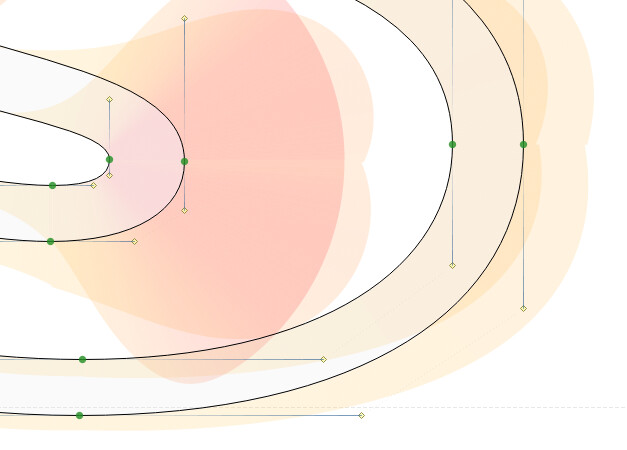
Specialised cad and drawing apps can visualise curvature, how fast a curve is bending:
(screenshot from a type design app)
It helps to get better curves, good enough for human eyes, but nowhere near good enough to build fast vehicles where curves must have G3 continuity. That requires different math for circles, and up to 5th degree Bezier curves. Specialised product design apps can do that. Continutity 1 : G0, G1, G2, G3 (aliasworkbench.com)
On a Mac, you can try this in Glyphs.app (30 day fully functional trial) with the free speedpunk extension.
All true!! But I think irrelevant in this discussion. If you’re shooting for perfect G3 continuity, you’re likely not running a Shapeoko Anyone at this level would be happy with G1 Tangent.
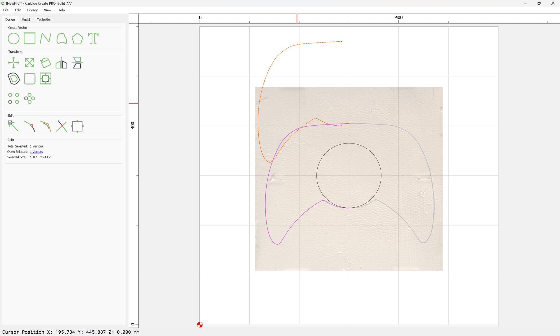
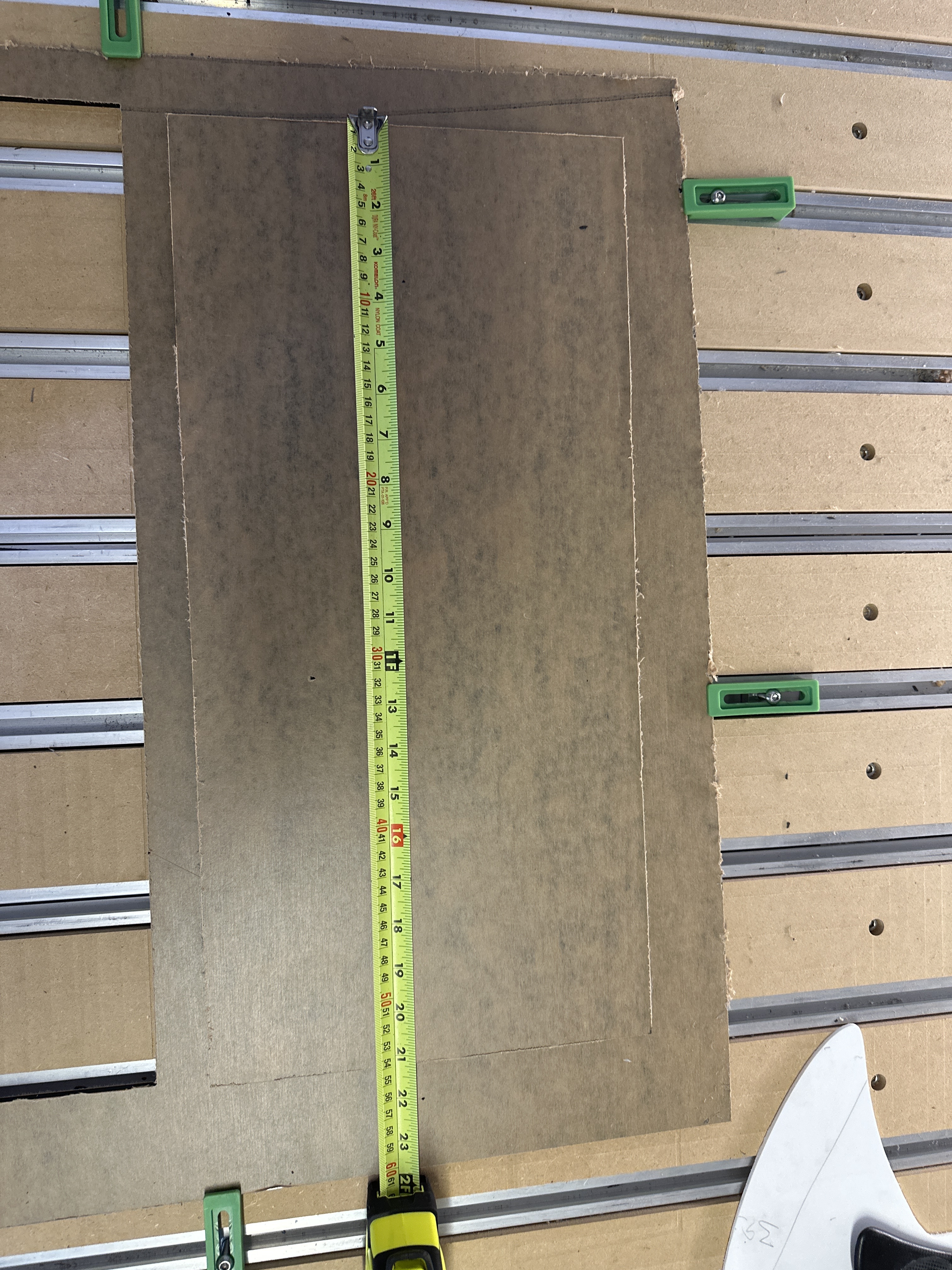
Sometimes you have to get creative, especially with a part like this that has not flat or square edges. Ideally a flatbed scanner would be a better way to get an image.
For measuring, place the part against a contractor’s square, and measure from those edges.
Question also I get confused with the offset direction. I’ve been using the Amana 51411K. To get my precise measurements, do I have to use inside/left? I want to know if inside/left cuts smaller and does outside/right cut bigger and does the no offset cut precise?
There is also climb vs. conventional milling to consider — but, dimensions should be accurate so long as one keeps cutting forces to within what is appropriate for the tool/material/machine.
If you want the geometry to describe the dimensions of a part which you are cutting out you will need to use an Outside contour.
To help in the dimensional accuracy it will further help to offset by endmill diameter plus 10% or so and cut as a pocket down to tab height or the penultimate pass. Where possible avoid slotting and add geometry and cut as a pocket
and/or
and consider leaving a roughing clearance and taking a finishing pass.
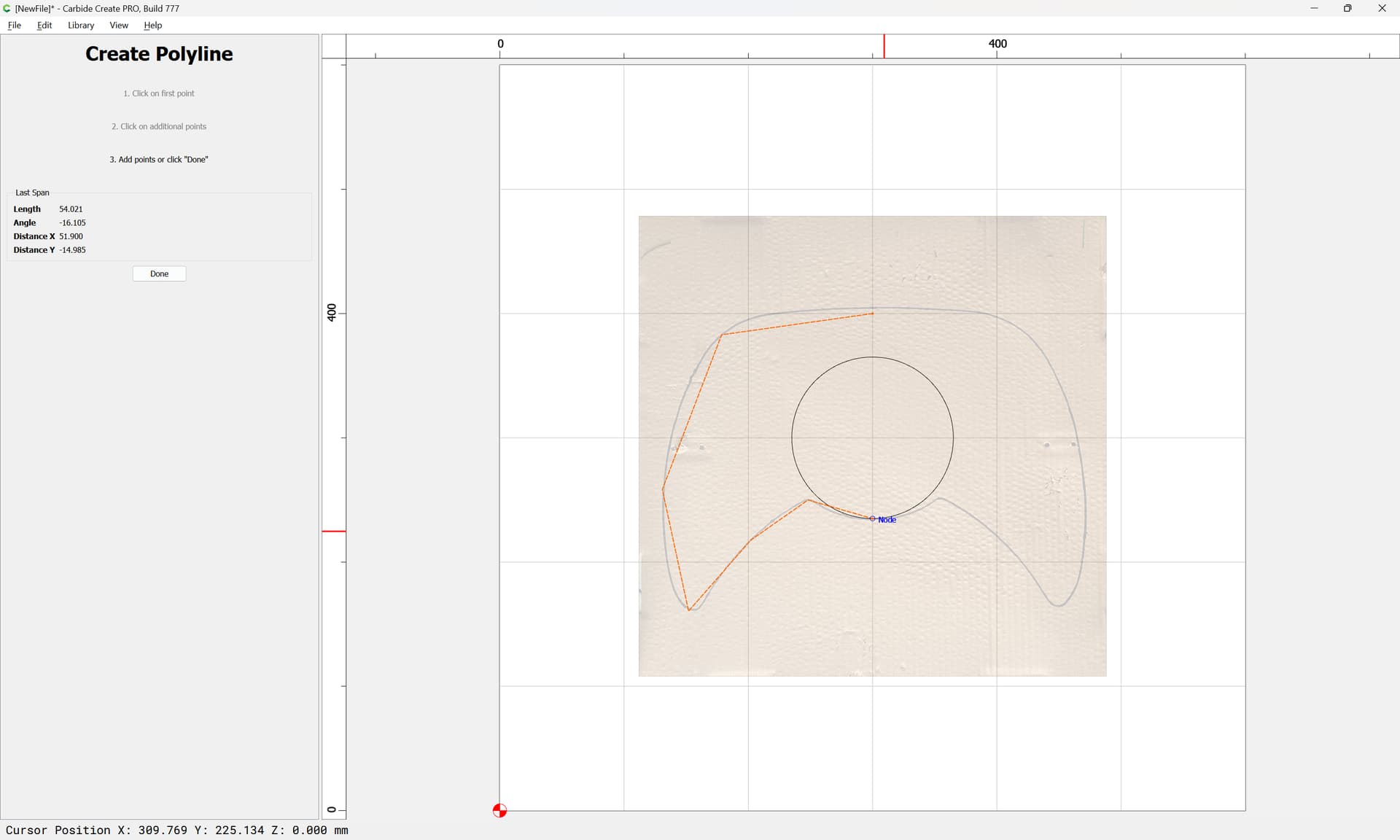
More than you might expect. Shapeoko can cut continuous curvature, and with standard Bezier curves one can get pretty close.
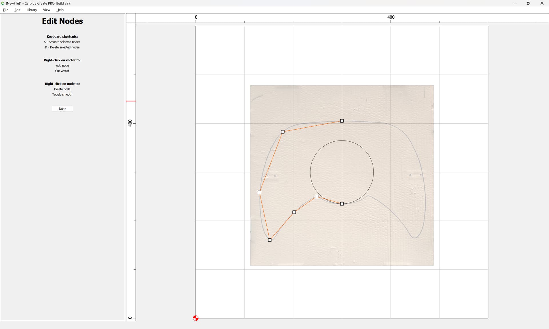
The finishing touch: when you add round corners to a square piece of wood, it might look ok, but it will not feel good because the curvature goes from zero to a lot. Fingers can be more sensitive to curvature than eyes are. A bit of sanding can make it feel a lot better, the sanding is just another way to aim for perfect curve continuity.
Funny, we used to have designers come in and ask us to “soften up the radii” when I was building wood patterns & models by hand (circa 1976 forward). We’d laugh, but they meant exactly what you described. A flat going from zero curvature, to a hard radius looks good, but you can definitely feel the change almost as if it’s a hard corner. A quick dusting with with fine grit sandpaper took care of it.
With CC, toolpaths are all converted to lines, no G02/G03, and certainly no NURBS motion.
You mentioned vehicles, and G3 for aerodynamics, I assumed you meant high speed trains, supersonic aircraft, missiles, turbine blades… etc…
Automotive designs class A with G3, but manufacturing can’t come close to holding those tolerances. They get the shape, and smooth surfaces, but the tolerance is in the “hundredths of an inch” range by the time it’s fastened to the car.