Is the faceting that I’m seeing in curves a limitation of the stepper motors used on the S5Pro, or is it being caused by the Carbide Create software? The faceting is subtle but noticeable. I have confirmed that my curves in carbide create are smooth curvatures, they’re not poly lines.
Maybe look at the G-code in a 3rd party simulator to see if the artifacts show up there & match the machining?
Do have a recommendation for a simulator?
The “faceting” is chatter. This produces unwanted marks from the tooling, inadequate workholding, feed speeds, cut depth, cut width, tool too hot melting aluminium to the cutter, stepover not appropriate to tool size or a blunt tool. Try using a sharp tool appropriate to the material (if it is aluminium you are cutting, then preferably use a single flute tool for good chip clearance) chip load may also be too high and you are potentially recutting chips, climb vs conventional milling may give a better result, tool could be loose in the collet, machine not bolted together tightly enough and parts move during cutting and so on…
Any or all of these reasons may be factors in producing chatter, which is the enemy of good clean and accurate work. My guess is a blunt tool and too fast a feed speed with too big a cut in depth or width. I use uncoated carbide tools when cutting aluminium.

3 Likes
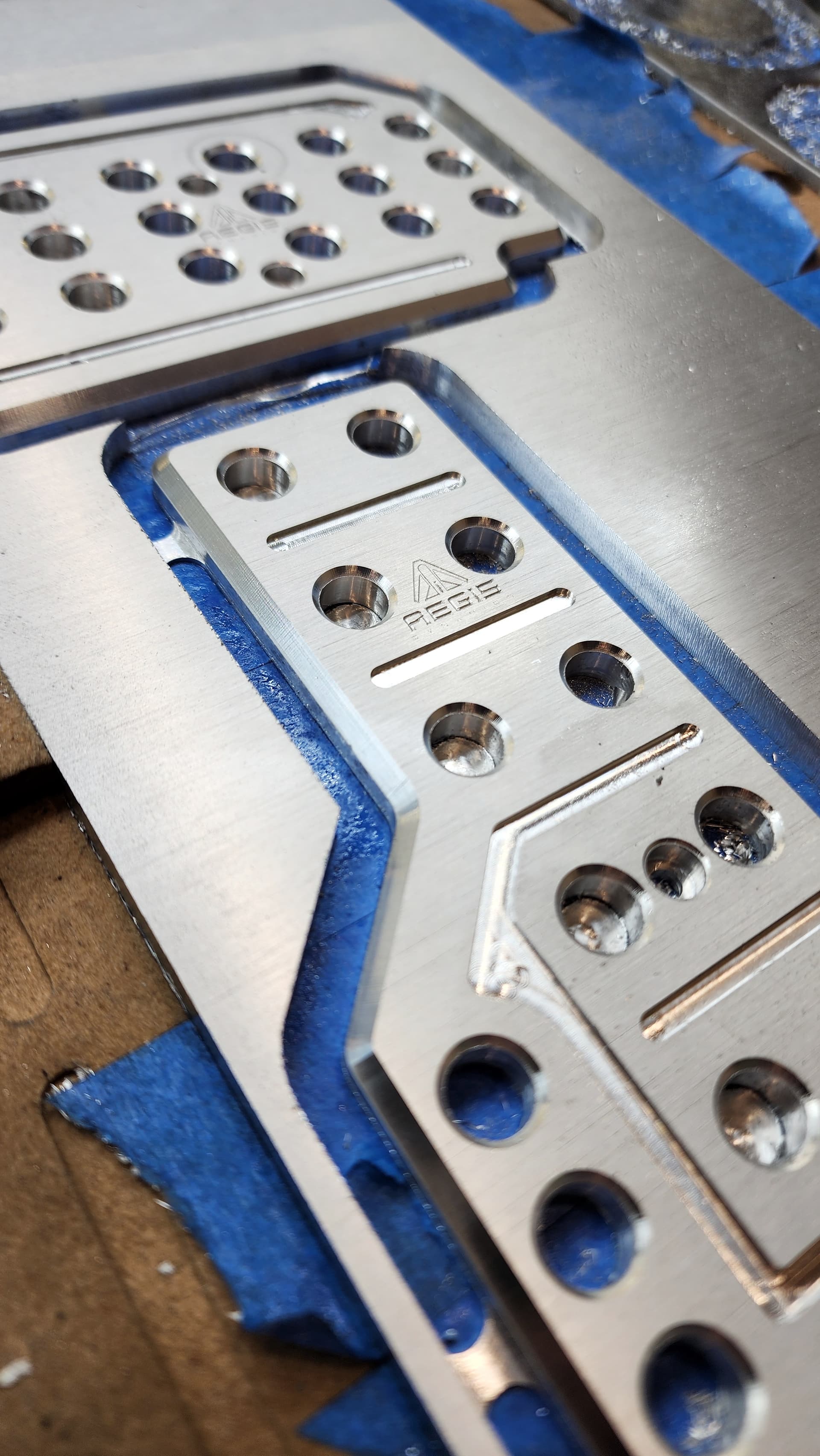
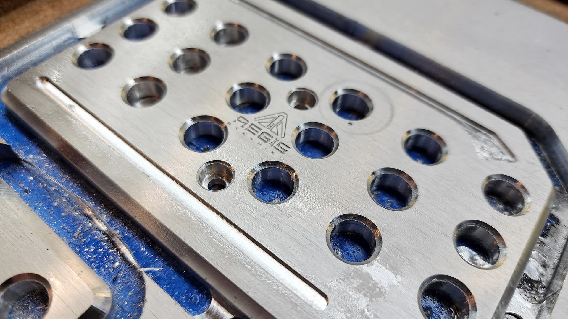
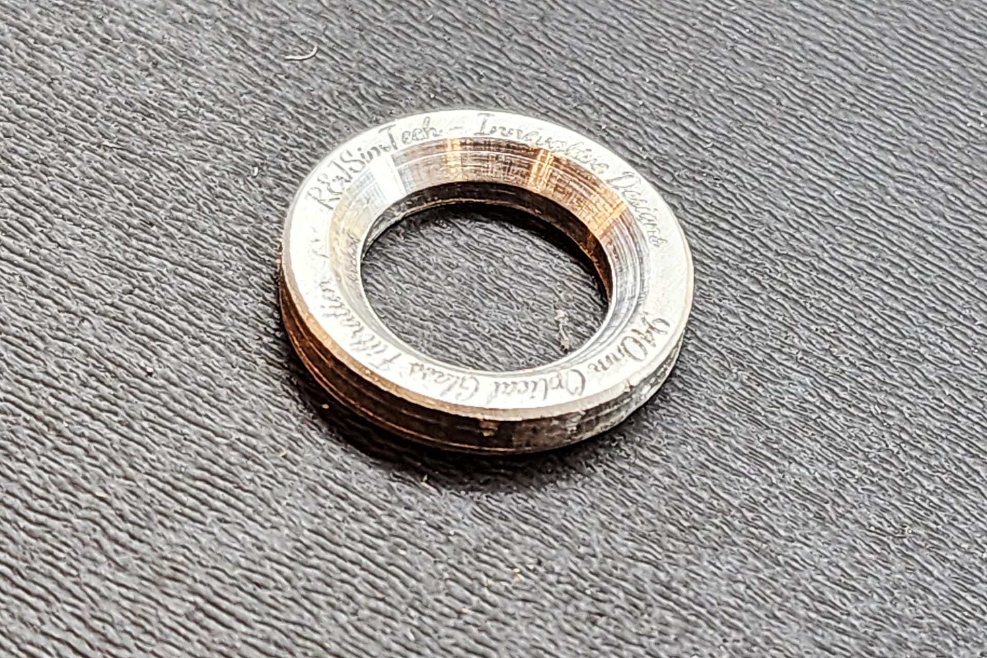
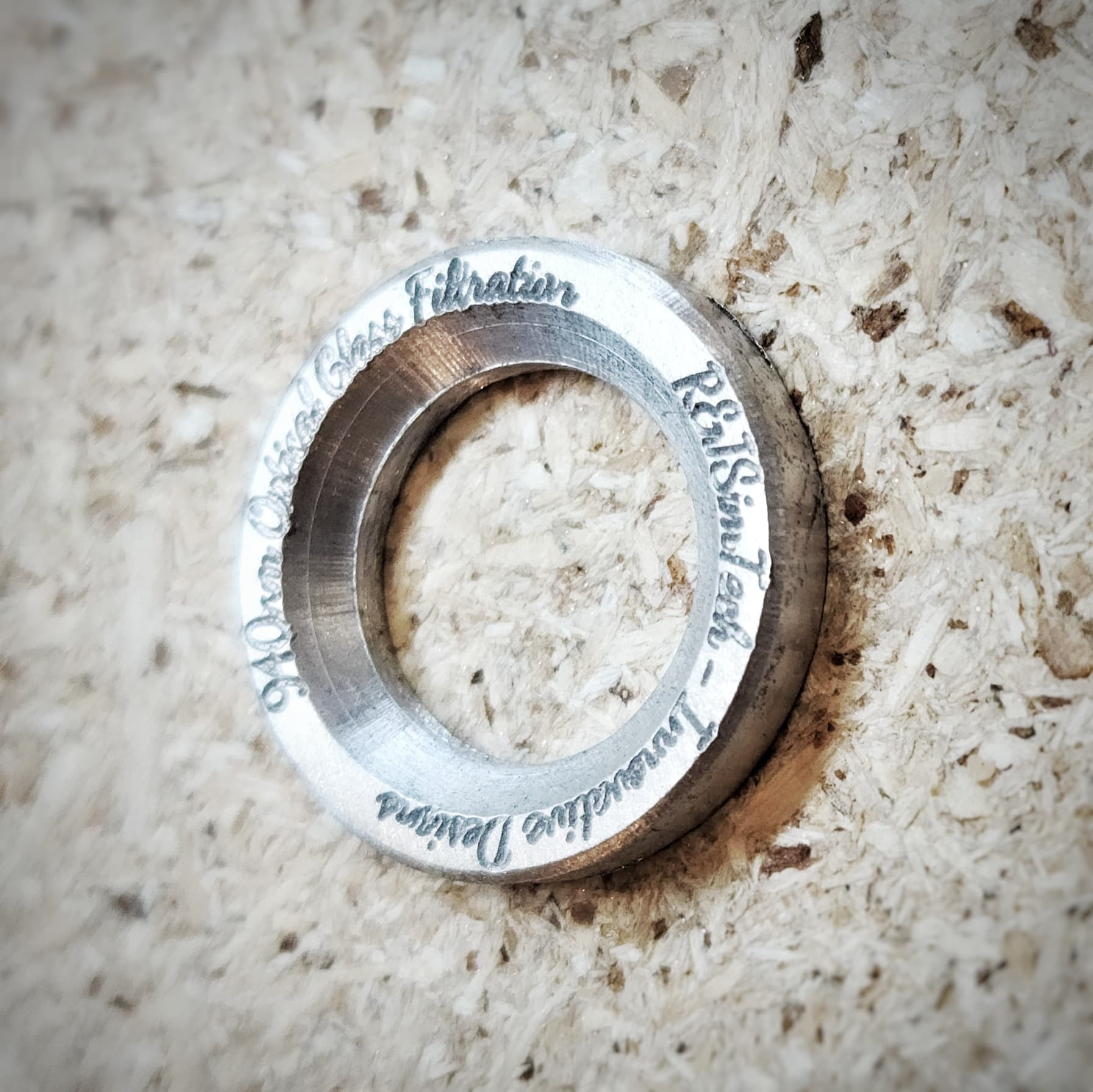
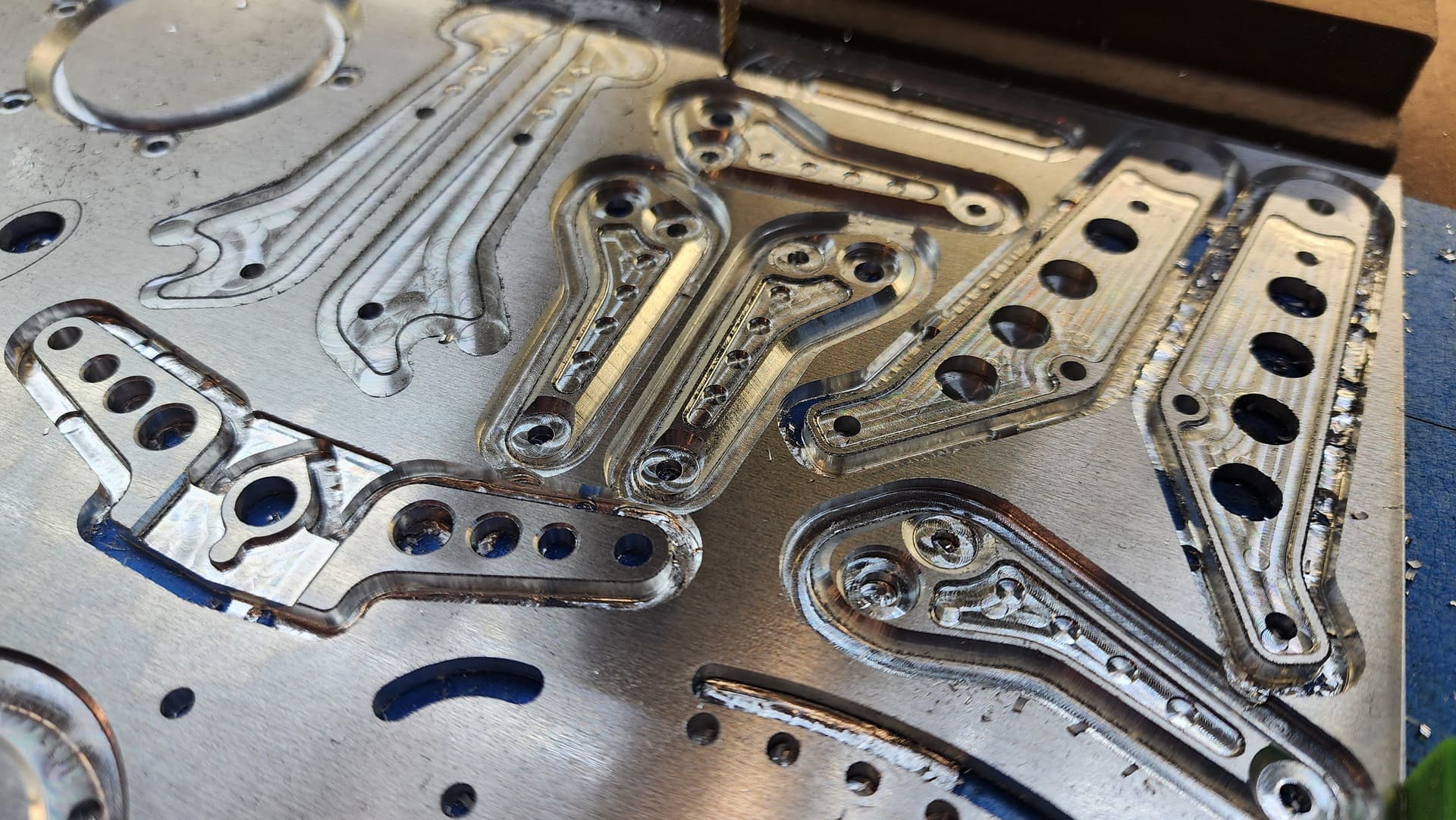
Thanks for the tips! I’ll definitely revisit my settings and do some experimenting. The pedals in the photos above turned out better than the small lens ring because I was using a new single flute 1/4" carbide end mill. But the biggest issue seems to be with chamfers, so I’ll likely need to find a higher quality chamfer end mill. I’ve been choking it up in the collet, slow rpms, fast feed rate (since it’s a 4 flute chamfer). But I’ll have to play with settings. I originally had an air hose attached to my spindle, but found it produced better cuts to just stand there with an air nozzle on my compressor. It has a higher psi spray, and evacuates chips quicker. The machine is square and trammed, and fairly solid, but not sure what I could do to stiffen it up any further. It’s on a solid table as well. About 3 thou change in Z if I lean on it.
1 Like
That is where your fairly comes in when you say “fairly solid”. If you are trying for accuracy then you have just clarified that you are working to a tolerance of plus or minus 0.003". Workholding may add another slip in the accuracy if you had a similar 0.003" deviation. As an example, this illustration would give you a combined possible deflection inaccuracy of 0.012".
Please would you clarify what you mean “choking it up in the collet”. Are you using a spindle with an ER11, ER16 or ER 20 collet size? I am taking it that 1/4" bit is fitting into an ER11 collet.
So I’m still getting faceting, and it is definitely not from feeds/speeds, chip evacuation, or chatter. These facets are evenly spaced, and the spaces spread out when the direction changes on the cut. It is without question the stepper motors or the gcode. But I’m not sure which. I’ve checked in carbide create and the curves are in fact curves and not faceted poly lines. Is this a limitation of the machine or the software?
Upload your file?
Detail photo of a project showing this problem?
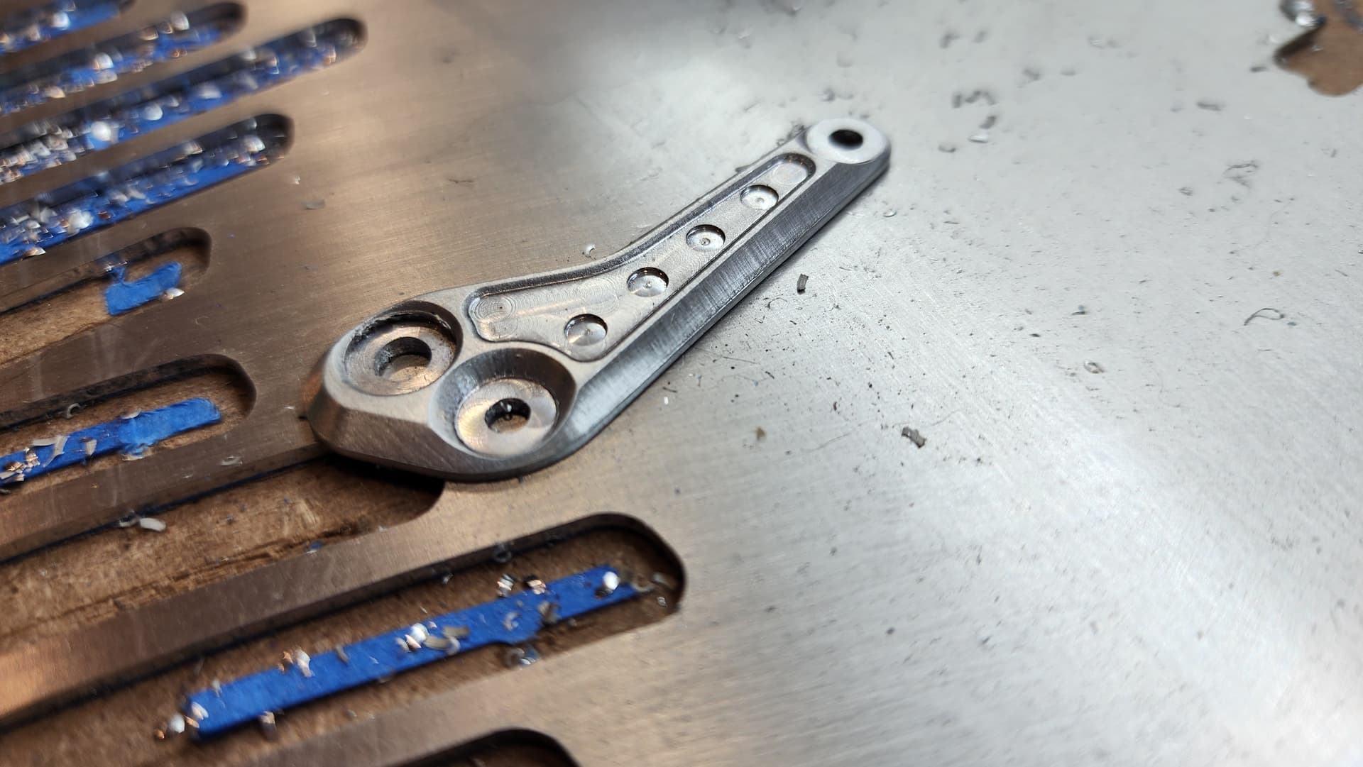
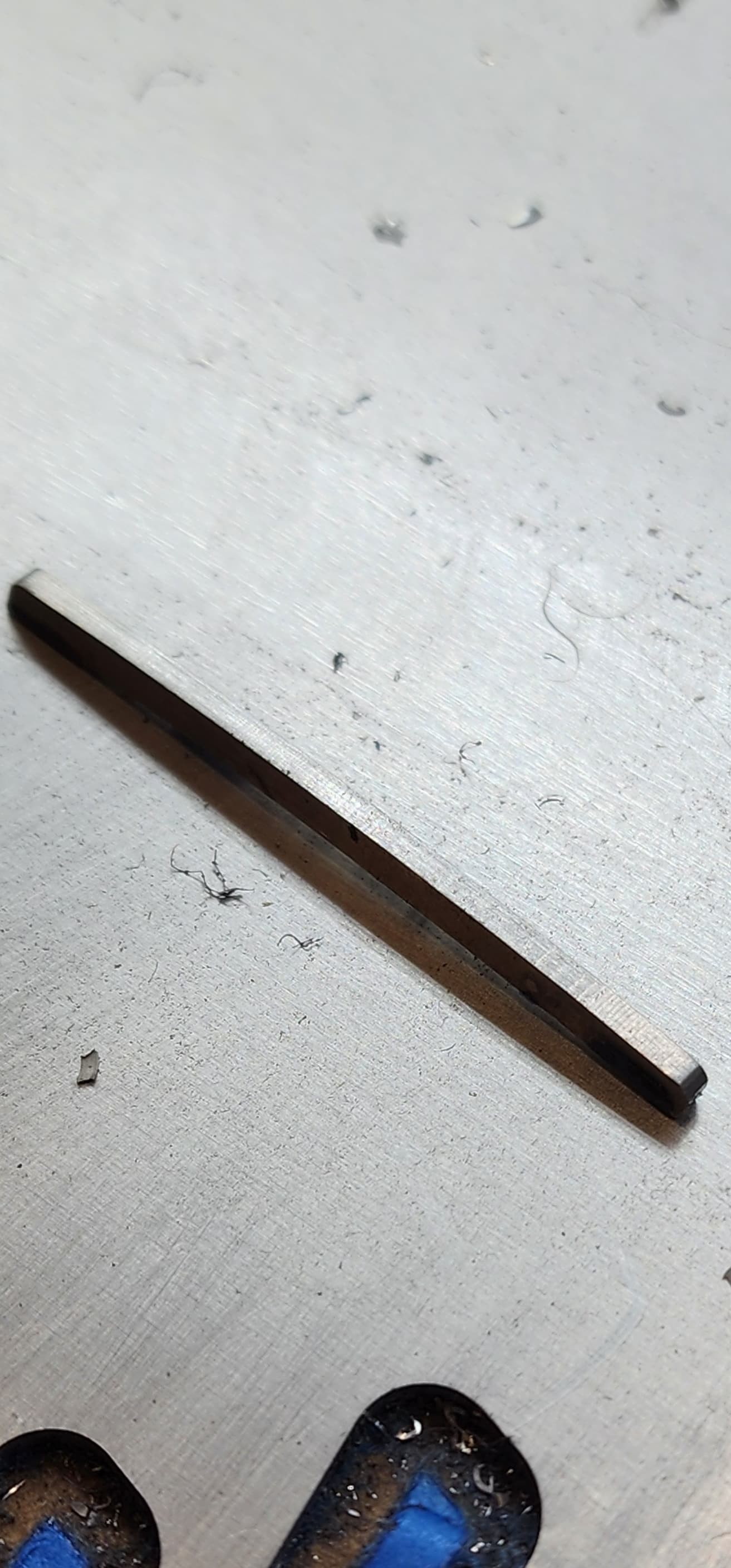
I’ve never been able to achieve a smooth curve on this machine. If that’s the limitation of the machine, I’d accept that for the low cost of the machine. I’m just wondering if there’s a way to improve it. I haven’t ruled out issues with feeds and speed entirely because occasionally I’ll see smooth curves, but I think that has to do with orientation to the machine axis. It’s most noticeable when a curve is nearly parallel with either x or y. Obviously the steppers are going to have a minimum tolerance, but because I see it so often, I’m wondering of there’s more to it than that. Or maybe I just have no idea what I’m doing lol
We have some videos which touch on surface finish at:
If you’ll post your .c2d file (or e-mail it in to support@carbide3d.com) and list the tooling and feeds and speeds you are using someone should be able to advise.
Hard to tell exactly what the issue is from your pics, but this could be due to the step resolution as you initially suspected.
Do you get a smooth face on a straight cut parallel to an axis? What about a straight cut slightly (say 1°) off axis?
Thank you for that link, I’ll go through those before having you guys spend time going through all of my toolpath settings. No sense in wasting your time if it’s user error.
Thanks!
Do you happen to know what the step resolution is on the S5pro stepper motors? And are there upgrades that are compatible with the S5pro?
I don’t. Can you see the $$ grbl settings?
This thread may be of interest.
Hmm, I may try to experiment with a cut 1° off axis and measuring the facets/steps and extrapolate from there. My feeds on a 1/8" single O flute is 10,000 rpm, 15 in/min, and 0.02" doc
Fundamentally, the faceting is caused by a limitation in resolution. Whether that be the resolution of the machine (physical size of stepper motor steps or controller) or Gcode can vary.
Carbide Create will export motion coordinates to 4 decimal places, but it does not use arc commands, which would be interpreted as mathematically perfect curves by the CNC. Instead it basically creates a bunch of tiny tiny straight line segments that approximate a circle. That is one potential source of faceting. You can try and game the system by using the Metric variant of the post processor, as the units will naturally be smaller, giving you better resolution.
The stepper motors do have a finite resolution. not much you can do about that.
The firmware of the Shapeoko also does a bit of behind the scenes magic to coordinate curved motion with the finite resolution of the stepper motors. One of its settings can be tweaked to try and maximize the fineness of curves. It is not cranked up by default, but you can try making it smaller. Enable MDI in the settings of Carbide Motion (if not already enabled), go to the MDI tab, and type in “$12=0.002” without quotes. The default value is 0.01mm which is a bit more coarse. Don’t go smaller than 0.002, or you may induce stuttering into the motion of your machine.
TLDR, you could probably do a little better than what’s shown, but there will always be a liiittle bit of faceting.
4 Likes
Thank you sir! I will give those suggestions a try.
The CNC Cookbook folks have a page discussing this sort of thing:
2 Likes
Have you tried geometry that was not made in CC ?
Another possibility is that CC geometry engine has resolution limits.
That would show up in reviewing the gcode in ncviewer.
Try a decent sized circle from various sources.
If you make a full circle using a G02 or G03, that would separate the authoring system ( not stroked ) from the machine interpretation.
2 Likes