As I wait to successfully place my order for the Shapeoko Pro XXL I’m jumping ahead to take the time to learn the software side as I’m new to CNC space. That said I’m currently working with Fusion 360 modeling a table/enclosure which I currently have a cube which represents the published footprint of the Shapeoko Pro XXL on the website. However I’m thinking it would be helpful having a 3D model of the machine to import into Fusion 360 and build around it so I can make design choices that align with the Shapeoko such as position my supports in the tabletop to align with holes in the base of the Pro and so on. Any chance anyone has gone through the trouble of modeling the Shapeoko Pro that could be shared for this project?
Not the pro, but Winston modeled one up (or had one) XL for his enclosure tied to this video:
Video description should have a fusion link in it. I think the Pro is a bit wider (maybe 2 inches?), so maybe account for that, and then for the XXL, it’d be worth going as deep as the enclosure is wide.
Hopefully someone else has a better starting point, but figured I’d toss this your way as at least one resource.
Edit: Could’ve sworn the shapeoko wiki had a 3d model of the different machines, but I can’t seem to find it currently.
It EDIT: was ENDEDIT on the Parts page:
c.f., https://wiki.shapeoko.com/index.php/Shapeoko_3#Drawings
Hey ! I wish for you to have nice machining time with your new baby 
rather that you wait for it and get not only the machine size you have to exactly get the move out size as well as the machine will pass out front the bed
also be sure if you want to use the normal router as Makita , Dewalt or you will get large 2400 spindle !
for enclosure materials please use steel to creat the enclosure it will help to discharge the static and keep your machine connected always with your computer
my first enclosure was from wood and I have many disconnecting issues
now I have no more with the steel enclosure as it always grounds with static discharge .
very good luck to you
These are for the 3 not Pro. Not sure how much they differ or if it matters…
Ah, good point.
Should still work if you just extend some extrusions and plates and swap around where the plates are mounted.
If anyone does make or find a good 3D model for the Pro XXL, I would be interested in getting a copy, especially if it is done in Fusion 360. I may end up just modeling it by hand.
I want to play around with Fusion’s new Machine Builder feature preview and do more accurate simulations using the machine model. Here is the feature if you want to drool over it.
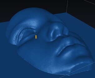
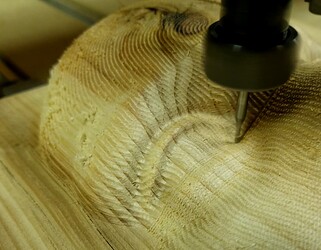
I’m about to do my first 3D carving, and I’m worried that the side of the router or the dust collector is going to crash the part.
(The yellow peg is the #111 1/16" Ball Cutter)
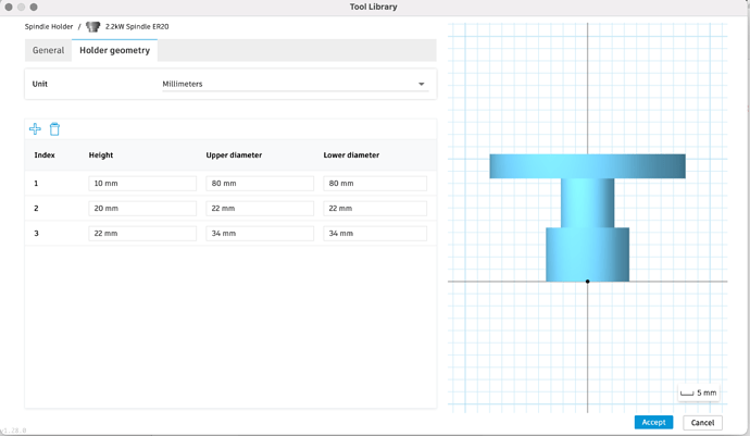
You may well be able to do most of what you want by adding a tool holder to your tools in the Fusion CAM library.
You build up a holder as a series of cylinders, here’s the nose of my 2.2kW spindle
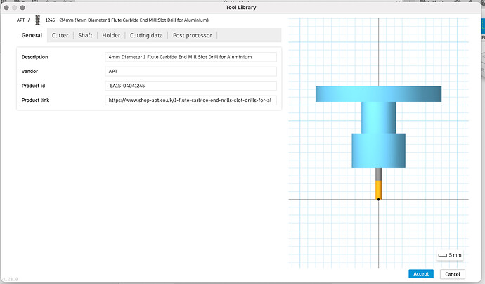
Then select the holder for your defined tools, including tool stick-out
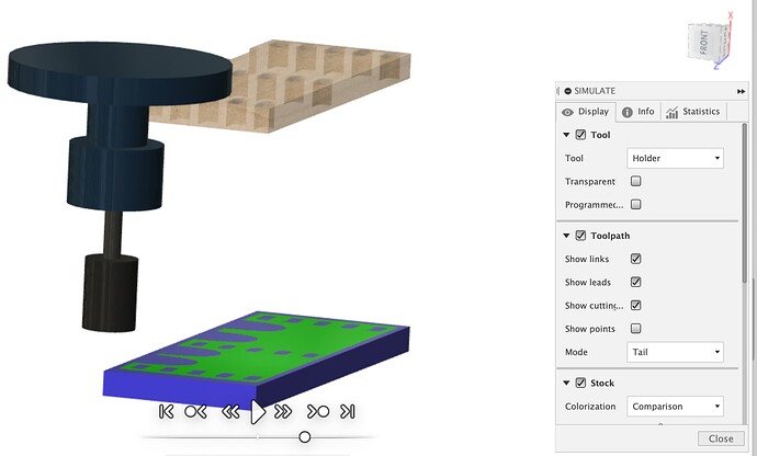
Then simulation (and I believe collision detection) will show the whole tool with ‘holder’ which in my case is not just the ER20 collet but the whole nose of the spindle.
You probably can’t do the droop of the dust shoe around the tool but you can certainly do the spindle and block out a bunch of space from collet height upward to represent your ‘occupied’ Z space, just remember this tracks the Z height as it’s tool not machine based.
HTH
Oh, good! I figured this was possible, I just didn’t dig around in the tool library enough. This should do everything I need.
However, it would be fun to watch the machine moving around in Fusion! 
This is for the Shapeoko 3 and not the Pro but basically what you would like to accomplish.
Wow! Cool feature. Thank you for sharing.
It’s fun, but I couldn’t find a good use to make it worth it.
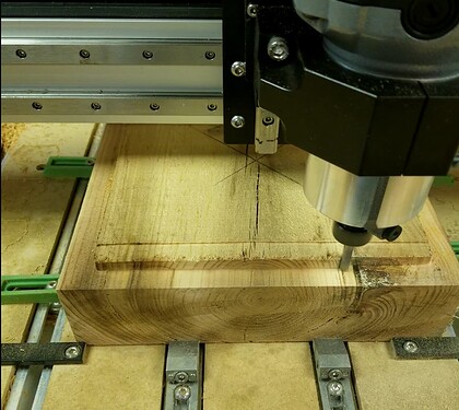
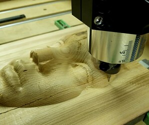
I just did my first 3D carving with a 3" thick piece of wood! I had to do some careful programming and simulation to make sure the spindle didn’t crash the stock. @LiamN got me set up with defining the tool holder in Fusion, but I could not run the machine with the dust collection in place because the tool holder is only defined by a bunch of cylinders.
If I understand this correctly, Fusion will do collision checking with the whole machine if you have it defined. All of my close-to-clearance cuts were on the sides and back, so if I had turned the model around, I might have been able to clear the dust collector, but I could not simulate it properly with just the tool holder geometry.
I’m willing to bet that someone at C3D or an outsourced company designed these machines in some 3D CADD software (Autodesk Inventor, Solidworks, etc.) I remember the pictures of the S4 on the website were of a rendering for a while when it first came out. One could easily export STEP files of the assembly and bring them into Fusion to set this up. Heck, send me the STEP files, and I’ll do it!
One could even reach out to Autodesk and get these machine configurations into their online library along with all of the HAAS and Tormach machines. Then everyone using Fusion would have access to them.
I feel like this would be a worthwhile project given that Fusion 360 is used by many hobbyists, as evidenced by all of the Creality, Prusa, and MakerBot definitions in the library.
I don’t think the Shapeoko Pro is open source…I don’t know why C3D would release the models.
If you really need it, I’d say just make a quick mock up. You really only need to model the work envelope correctly. You don’t need Motors and pulleys and belt tensioners and the like to do what you want.
