Hello,
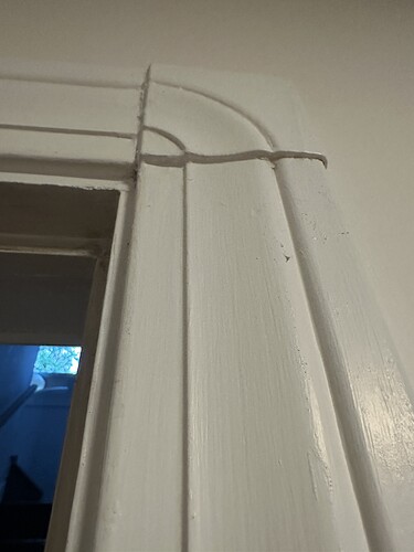
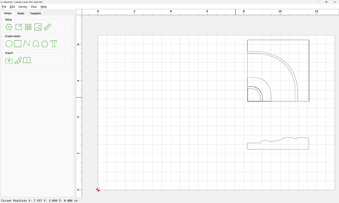
I’m pretty new to 3D modeling with carbide create V7 pro, and I’m stuck on a project. The included photo shows a square piece of trim or a ‘rosette’ I’m trying to recreate for someone, it needs to be slightly different due to new trim in their house but the profile is pretty much the same.
I have all the measurements and a good sketch of the dimensions. My question is how to 3D model this piece with each part of the design being a specific thickness. I understand how to make a grayscale image to carve in 3d, but not how to make each point in the design a specific height or depth to match the thickness of existing trim. Is this possible? And would a greyscale map be the right way to go about modeling something like this? Thanks for any advice you can give to a newbie.
Start by drawing up the design in profile, then model it as a full circle — that should make things easier, possibly even obvious.
If you have difficulties, upload the profile drawing and your effort and we can walk through this with you.
It is possible to create a height/depth map and directly map light/dark to the Z-axis dimensions — a simplistic approach to this is shown at:
or:
or, one can work more directly, just drawing geometry which then cuts away:
there is at least one where a number of different tools are shown to realize a specific profile — post a drawing of the profile w/ measurements and we will work through that with you if you get stuck.
Thank you so much for the helpful Info, I’ll proceed with drawing it in profile and come back if I get stuck ![]()
Hello,
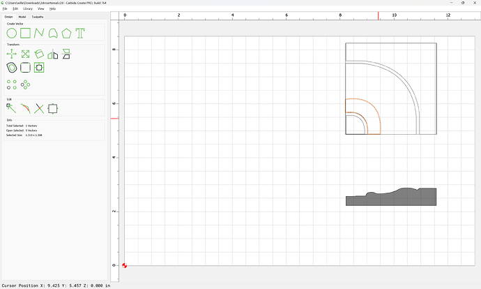
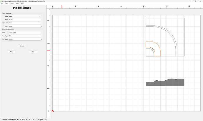
I’ve learned a lot from the links you posted, thanks! Can you elaborate on what it means to model it in a full circle? I drew the profile and played around with modeling tools and now seem to be stuck. I’m uploading my file so you can see. Thank you again.
3drosettereal.c2d (64 KB)
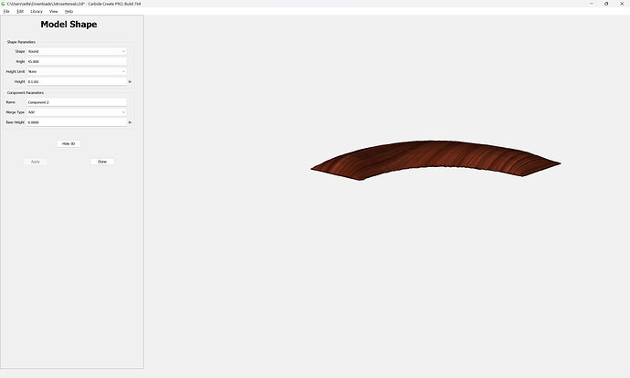
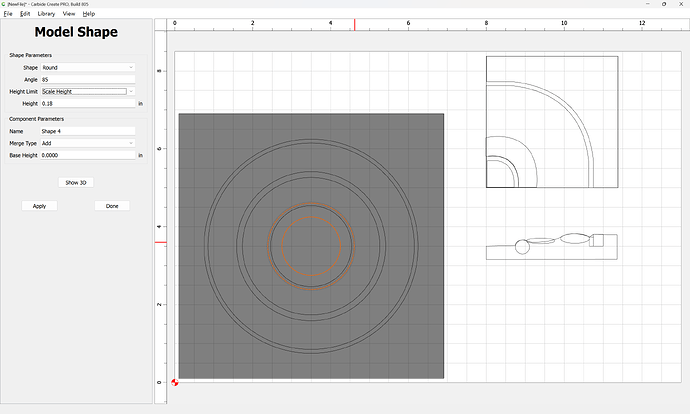
If you try to model a region rounded:
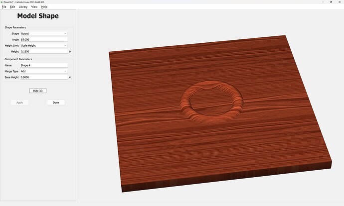
it will be rounded all around:
It will be necessary to draw things up for all four quadrants — this probably matches how this was made originally, likely on a lathe, cut as a square, and then that square divided into quarters.
Hang on and we’ll walk through this in v8 (it would work in v7, but if there isn’t a reason to not test v8, then it should get used).
First, open the file in v8:
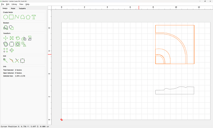
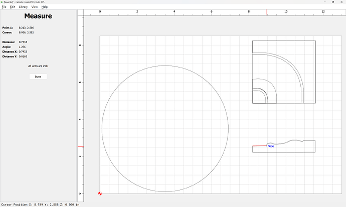
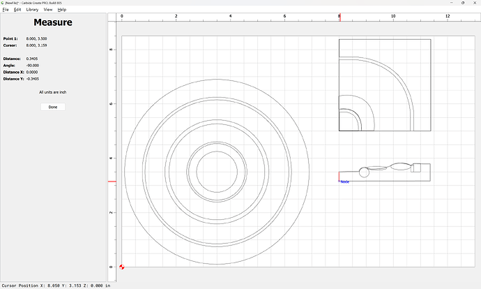
Get the overall measurements:
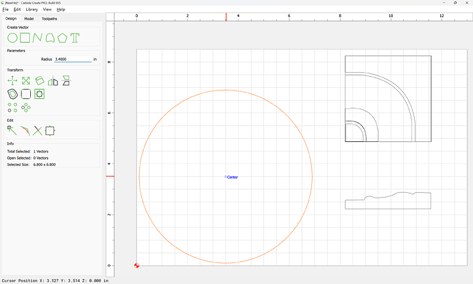
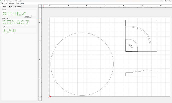
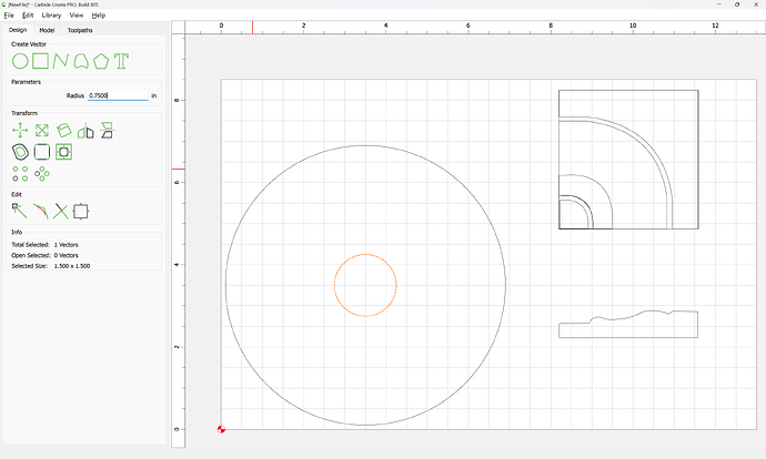
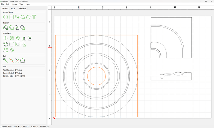
and start by drawing a circle of that dimension:
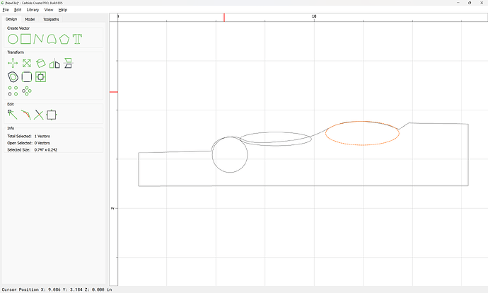
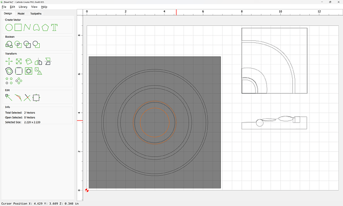
Then measure each aspect of the design:
(rounding off if desired to make things easier)
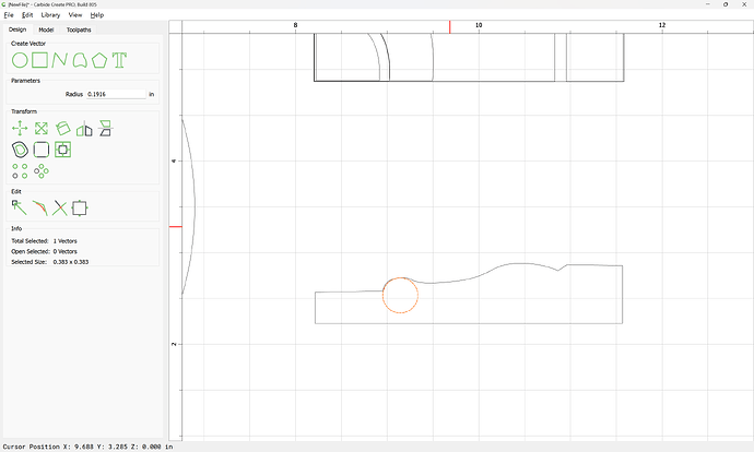
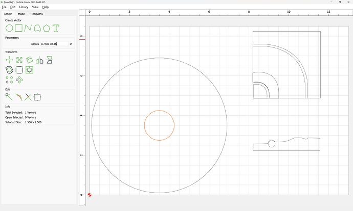
and if need be, draw in circles to help approximate various dimensions:
Or, ovals:
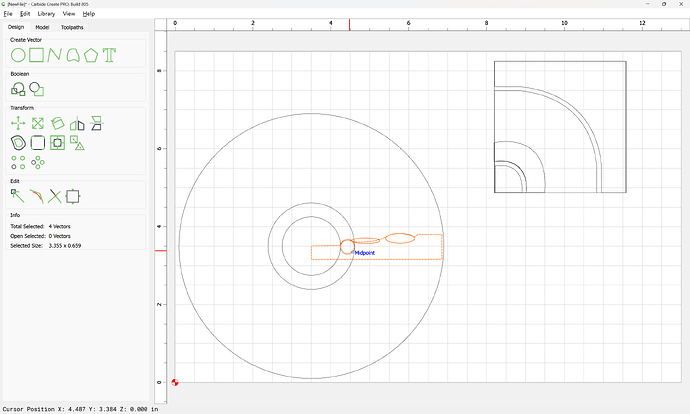
and add circles as necessary until all needful regions are delineated — not that it may help to reposition the profile:
Note that it may help to drop a vertical feature to prevent angular distortion:
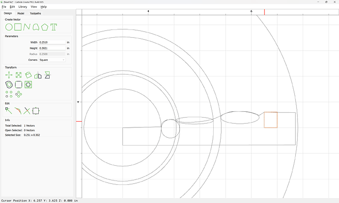
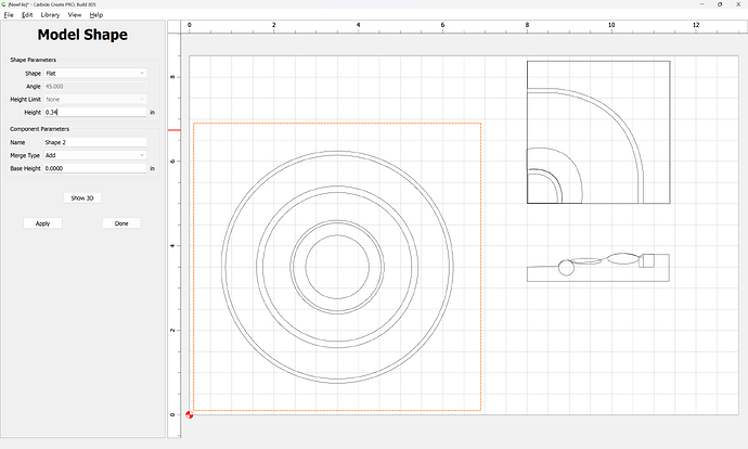
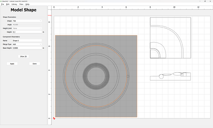
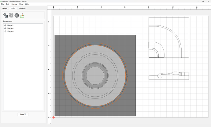
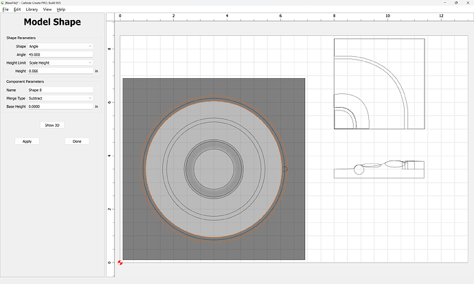
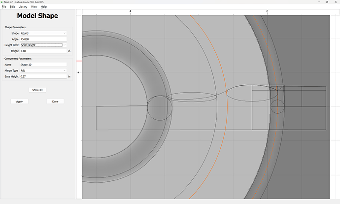
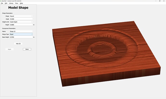
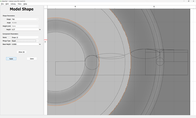
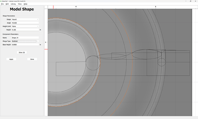
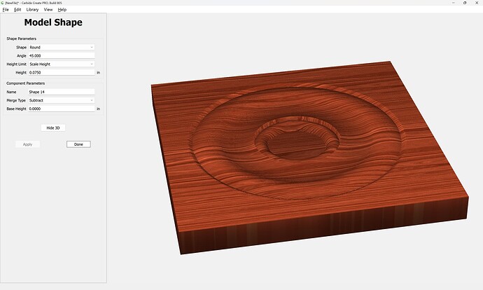
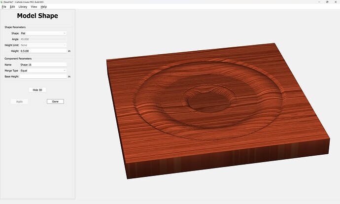
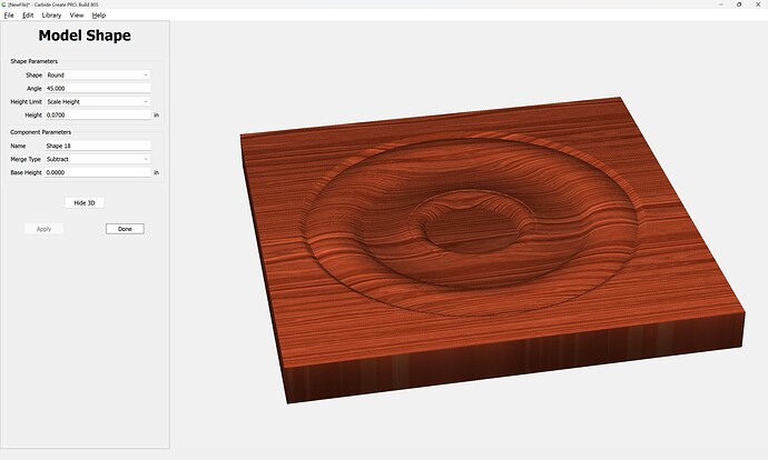
Then, model each aspect of the design, measuring as necessary:
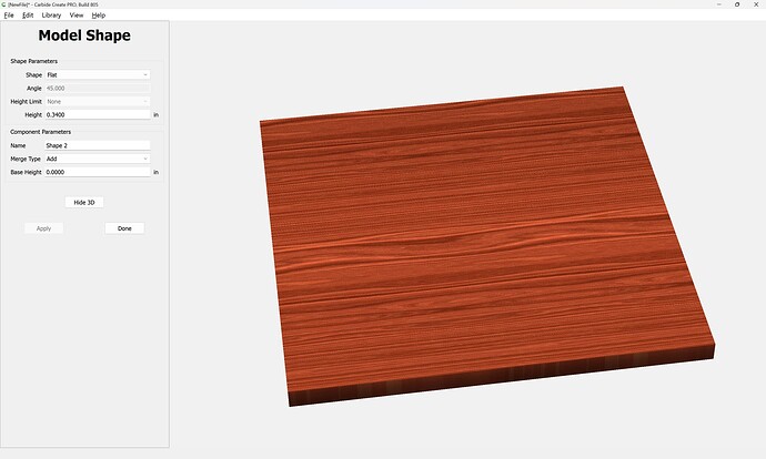
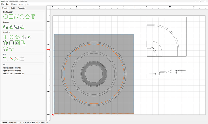
Note that it will be needful to ensure that the outermost element is a square:
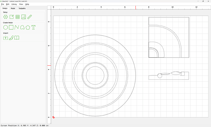
Repeat this, experimenting as necessary…
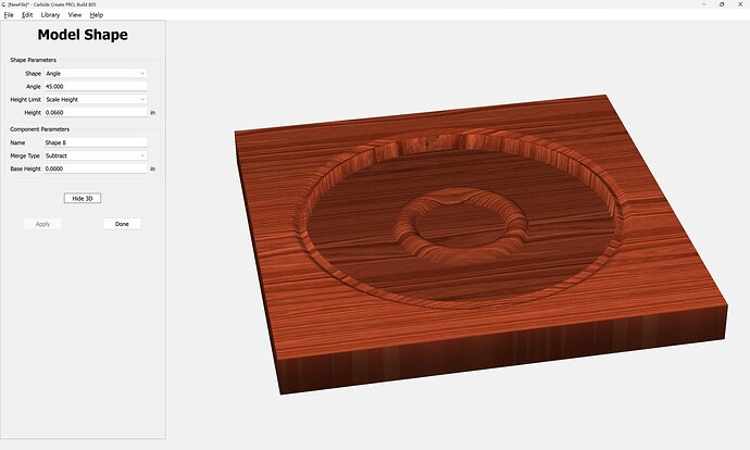
Until one arrives at:
Attached as a v8 file:
3drosettereal_3D_v8.c2d (472 KB)
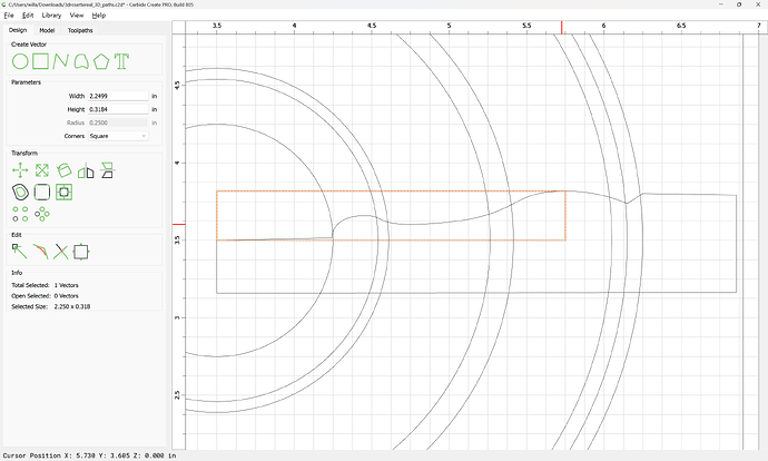
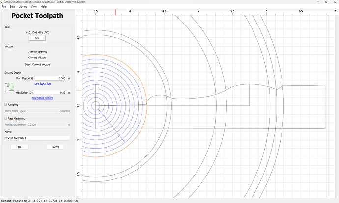
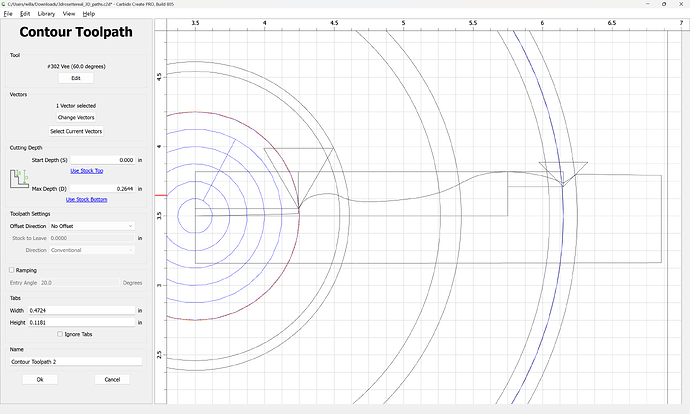
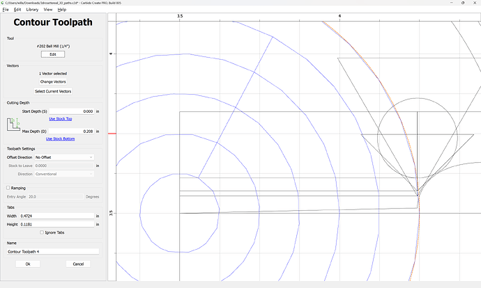
Alternately, one can just use a series of No-offset Contour toolpaths w/ a suitable array of tool profiles to just cut the design more directly…
The flat regions are quite straight-forward:
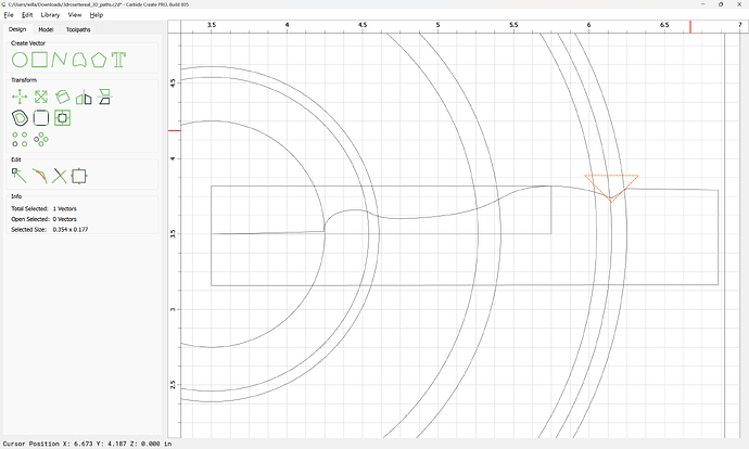
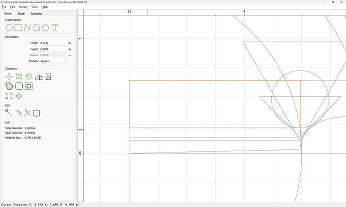
Similarly, the angled region is easily done — draw the tool up in profile:
and measure how deeply it needs to cut:
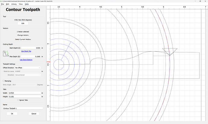
which last technique is then used for the balance — draw the various V and ball-nose tools which one has available in profile, then position copies of each relative to the profile and determine how deeply one must cut along each circle as noted in the afore-mentioned links.
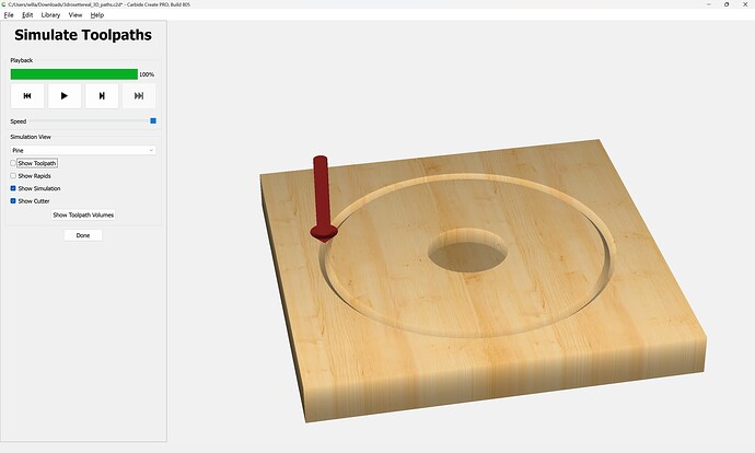
Repeating this until one arrives at the desired result.
Here is a beginning in CC v8:
3drosettereal_3D_paths.c2d (76 KB)
Lastly, one could work up this design in a 3D CAD program or other tool.
Wow, you’re awesome!! Thank you for the detailed instructions and sharing the file. This has made the process seem much more clear to me now, I’m learning a lot. Going to dive into this after work ![]()
This topic was automatically closed after 30 days. New replies are no longer allowed.
