A box of a different size

Revisiting:

We have an interesting examination of “What are the dimensions of a box?” where if we make it using thicker material (13mm was requested) then one gets to examine the proportions.

Unfortunately, the BlockSCAD site is down at the moment (powerful argument against web apps), so we use instead:

and change the dimensions there to 13mm (well as near as 4 digits of precision in Imperial will allow) and we get:

which seems rather heavy and clunky in terms of proportion, and which reiterates how difficult it is to cut this joint with the very thin projection covering the joinery, so revisiting things seems in order.

The difference between the original thickness of ~8.5mm and the new thickness of 13mm yields a dimensional difference along both axes of 9mm, which when converted to Imperial (0.35433071") is reasonably close to 3/8", so we adjust based on that to arrive at:

which has proportions of 1 (height) to 2.25 (depth) to 4.25 (width) — not the golden mean, but seems reasonably pleasing/workable (and certainly an improvement over the initial with its very small interior space) — this one would have an interior space of:

  • height — 2" less 26mm is almost 1"
  • depth — 4.5" less 26mm is almost 3.5"
  • width — 8.5" less 26mm is almost 7.5" — about enough length for a full-length Mirado “Black Warrior” pencil

Re-working the joinery will involve a couple of tools, since the intent is to have a full miter at the ends, and to cut this in the simplest fashion possible. Necessary tools:

  • a large diameter 90 degree V endmill such as:
  • a narrow 90 degree V endmill such as:
  • a 90 degree square endmill which will match the diameter of the above tool (a #102 should be fine, though you may want to consider a downcut tool)

  • two roundover tools — one whose radius matches that of the above two tools such as:

  • a second which would ideally have a radius which would add up to a diameter close to that of the thickness of the stock — I believe a 1/4" radius (6.35mm doubled to 12.7mm is reasonably close to 13mm for woodworking purposes — worst case, cut a bit deep and ease the beginning/end of the cut w/ a file or some sandpaper)

https://www.whitesiderouterbits.com/products/1572

for more on roundover tooling see:

An initial pass on this sort of joinery is being worked up at:

First step is to lay out rectangles, the dimensions of which match the stock which we are using:

and to set the stock dimension to match:

Placement of the rectangles initially is determined by how the joinery of the bottom will be handled — there are two options:

  • a rabbet as was done for the bottom in: As funny as a $3 dollar box - #2 by WillAdams
  • the same style of joinery used for the the side and front/back corners — this should be more straight-forward, and we will assume the use of a sheet good which makes setting up the toolpaths easier (and which has the advantage of being more efficient in terms of stock usage) — adjust as necessary if using a board
1 Like

But, we have a change request:

outside length of approximately 14”, width 4.5”, depth of 4”. I have an old music box that’s slated to be refinished in the near future and these are the rough dimensions from it. I’m hoping that this will also be a music box at some point.

Plugging those dimensions into the OpenSCAD file we get:

so we change the dimensions to match:

1 Like

First, the geometry must be modified to accommodate the lid, so we draw in a rectangle which matches how this will be cut:

and use Trim Vectors to remove it from the front/back:

OK

OK

Join Vectors:

dupe and flip and re-arrange:

1 Like

I find this all easier to visualize working from the bottom up (similarly, making the stock narrow will reduce zooming in/out until we get to the lid) — toolpaths can then be arranged for optimal cutting. First is the narrow V carving — the topology of the arrangement doesn’t allow for a single line to do this w/o repeating, but drawing in the corners and selecting the box itself will work:

1 Like

Arguably, it would be better if one will need to take things apart to draw individual elements for each — addressing this is left as an exercise for the reader.

Draw in polylines as wide and as tall as the stock and position them at the ends of the joints — probably this is all easier if we have separate layers for each sort of geometry:

(I also went back and changed these to use “T” as the thickness and associated each toolpath with a matching layer)

1 Like

We draw up what we have thus far:

and then dupe the small tool and align it (well, the tip of it) at the top/inside of the joint:

and draw in a square to show the “fingers” and matching recesses of the joint:

and a matching square shows how much things need to be inset from the inside of the box:

(which is, of course, the radius of the tool)

Making this for the bottom of the box is simple since it is just an inset rectangle:

but for the sides and front/back wants open geometry — there are a number of ways to make this, but possibly the most straight-forward is to just draw some squares centered on the corners for one side and one of the pair of front/back:

and then use the midpoints and corners to draw the desired geometry:

then duplicate it and move it to an appropriate layer:

which after a bit of dimension correction nets us:

(doubled up twice when it should have been only once)

1 Like

Next we need the geometry which allows us to clear for the top of the joinery — select all the part outlines and offset by small endmill diameter plus 10% or so:

Delete the unneeded inner element:

Then get the geometry used for the V cut down to radius depth:

and copy-paste it:

and then move all this to a new layer:

It will be necessary to close the open geometry — this is easily done by drawing in lines for the side, but the front/back with their feature for the lid demand a bit of care (and this also shows how well-suited to this the previous design was)

Draw in an oversize rectangle in register with the outline and use Trim Vectors to get to what is needed:

OK

OK

Join Vectors

dupe and align and delete open geometry:

then assign a pocket toolpath:

3 Likes

Lastly we have the actual joinery — in the past I’ve drawn in the notches/recesses and stitched them together, but in retrospect, that’s not the best approach — instead, draw the fingers and add them to a duplicate of the geometry which defines the recesses, but align them with the inside of the box:

But first, determine the width/number of fingers — dividing:

329.601/3.5 == 94.1717143

We need an odd number, so rounding down to 93 we get:

329.601/93 == 3.54409677

and we will need to make 47 protrusions and 46 recesses which is easily done with a Linear Array (albeit w/ one extra piece of geometry which will need to be deleted):

Rounding unfortunately results in a slight discrepancy:

which is most expediently dealt w/ by centering things.

We then clean up and union things:

and repeat a similar process for the other edges/joints.

2 Likes

Once everything is put in place:

it is necessary to extend the ends:

at which point toolpaths may be assigned:

toolpaths are then re-arranged to cut from top–bottom in the most efficient fashion possible:

1 Like

Next, we add geometry to trim things all the way through and adjust the balance of things to prevent interference:

1 Like

Lastly, the lid has to be set up — see:

for how this would be done.

2 Likes

Please note that the above files will need to be tested in a piece of scrap — the last time I worked up joinery:

when it went together for a dry fit, it required a great deal of force to get things together and then it wouldn’t come apart.

A further consideration is that it will also be necessary to make a fixture/jig to drill the holes for the hinge pins.

I also don’t know that rounding things helps — revisiting this using only rectangles seems a worthwhile check, and starting from the top and working down should make the toolpaths more efficient, and make things easier to visualize.

Once again, from the top…

Step 1:

Draw the outlines of the box parts (bottom, sides, front/back):

Step 2: draw in the geometry for the lid cutouts and round them as is appropriate and then use Trim Vectors to create the geometry for the front/back:

Step 3: draw in the lid and set its size, taking the sides into account:

(I’m pretty sure the lid in the above file doesn’t take the sides into account)

Move the lid off to the side and put it on its own layer.

Step 4: Draw things up in profile — the necessary dimension is how much the projecting joinery needs to be cut down so as to ensure that it will fit into the recesses — since one part will be rotated 90 degrees, there are a couple of possible options:

  • cut dogbones — this removes a lot of material and increases the voids in the joint, and I worry that it creates potential points of failure
  • cut the recesses up to the interior space of the box — this creates the possibility that they will show, but if lining a box, may not be an issue
  • using a roundover tool on the tops
  • cut the protruding joinery down lower — this actually has the advantage of leaving more material around the potentially fragile sections holding the lid in pace, so seems worth trying

Select all of the parts and inset them by that distance, and also offset them to the outside by small tool diameter plus 10%:

Then, extend the front/back parts so that they are not inset at the top, since this only needs to be done where there is joinery (using a duplicate of the front/back):

OK
OK

Join Vectors and duplicate and mirror and drag into alignment, extend the side panel interiors, draw in the geometry for the bottom and clean up and move the geometry which defines where the initial pocket will be cut to a new layer:

Set up and preview the toolpath for this layer:

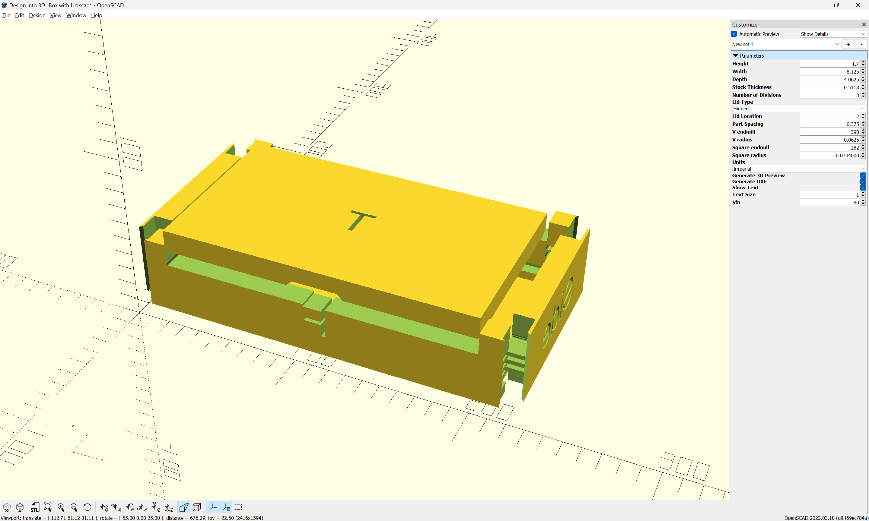
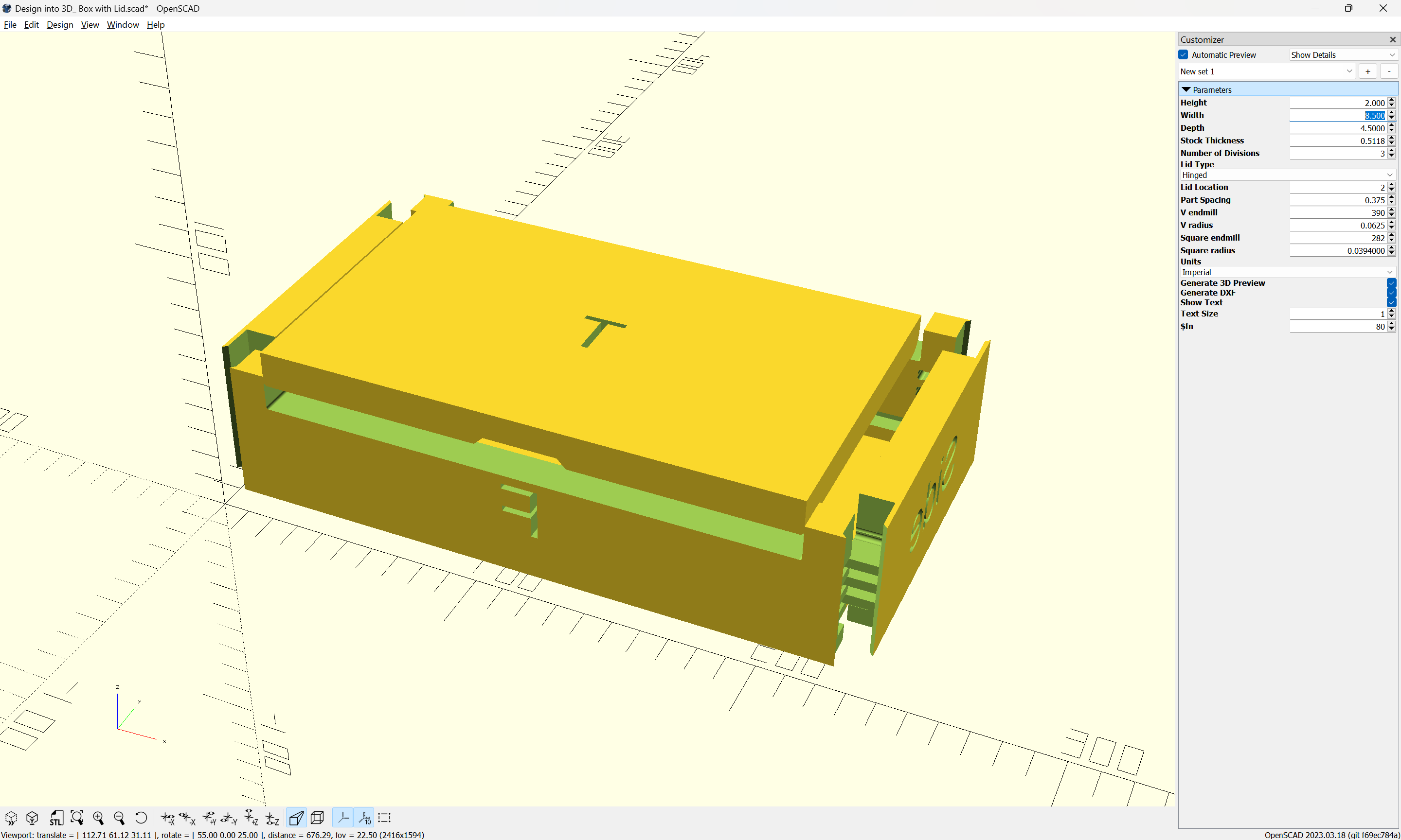
Step 5. (or maybe 6, depends on how you’re counting)

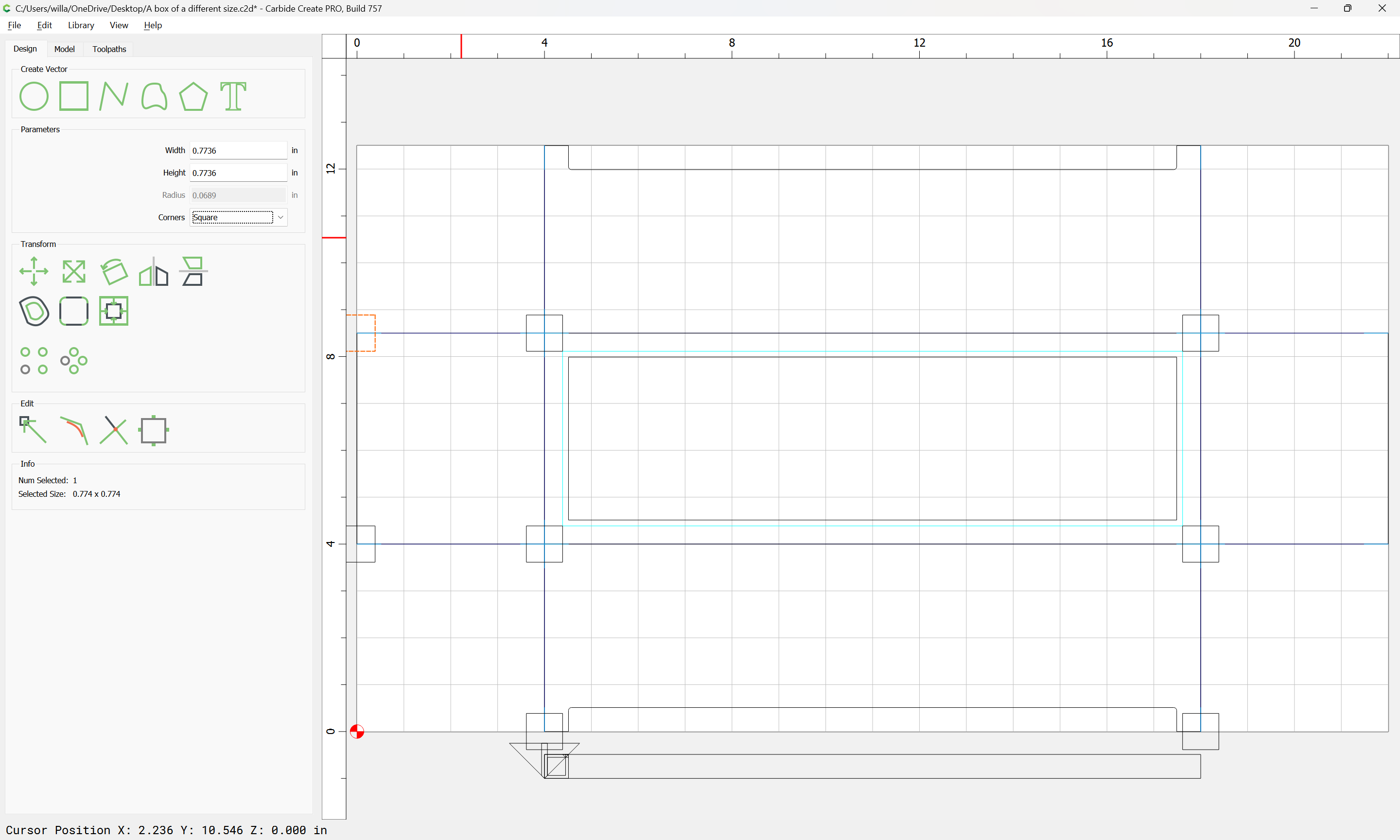
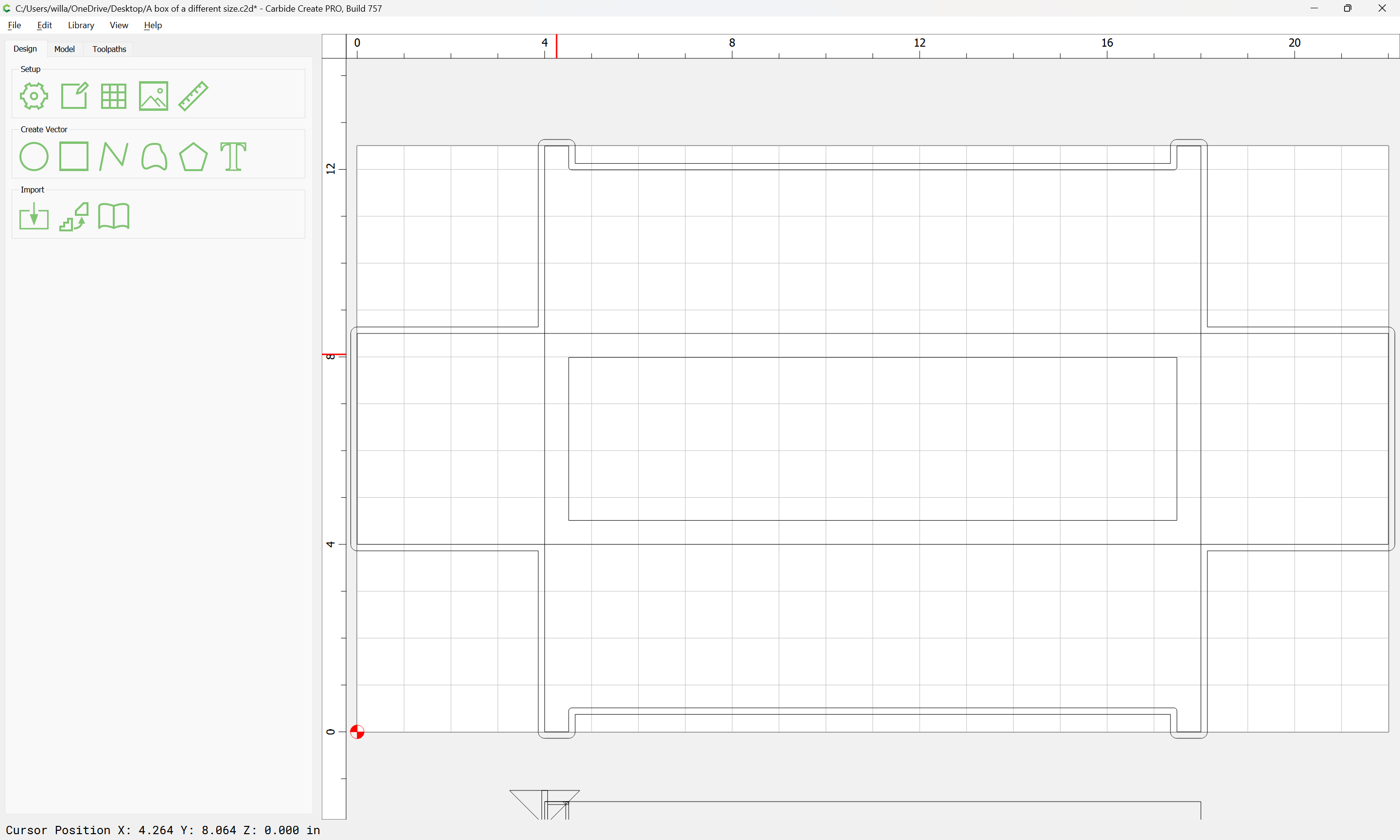
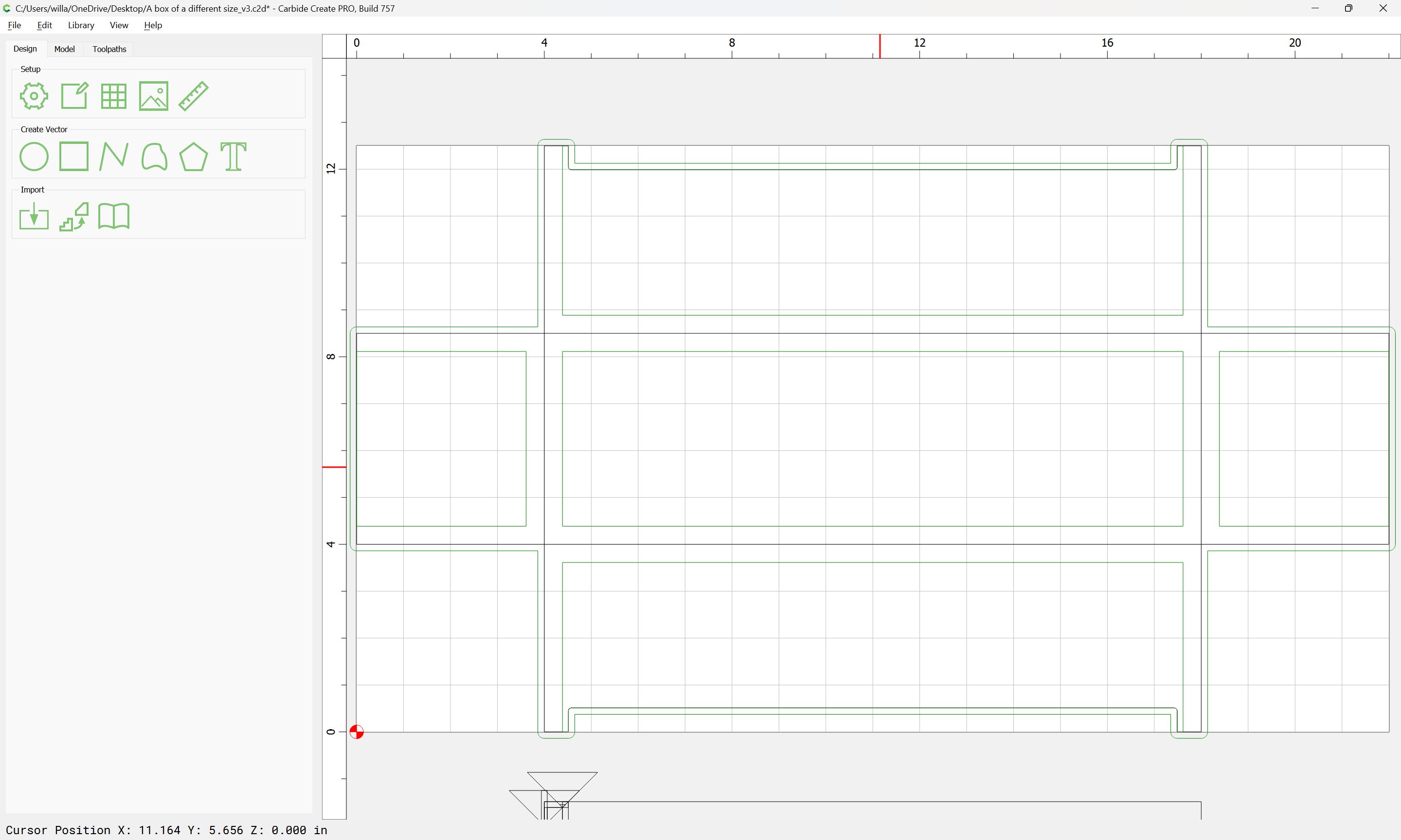
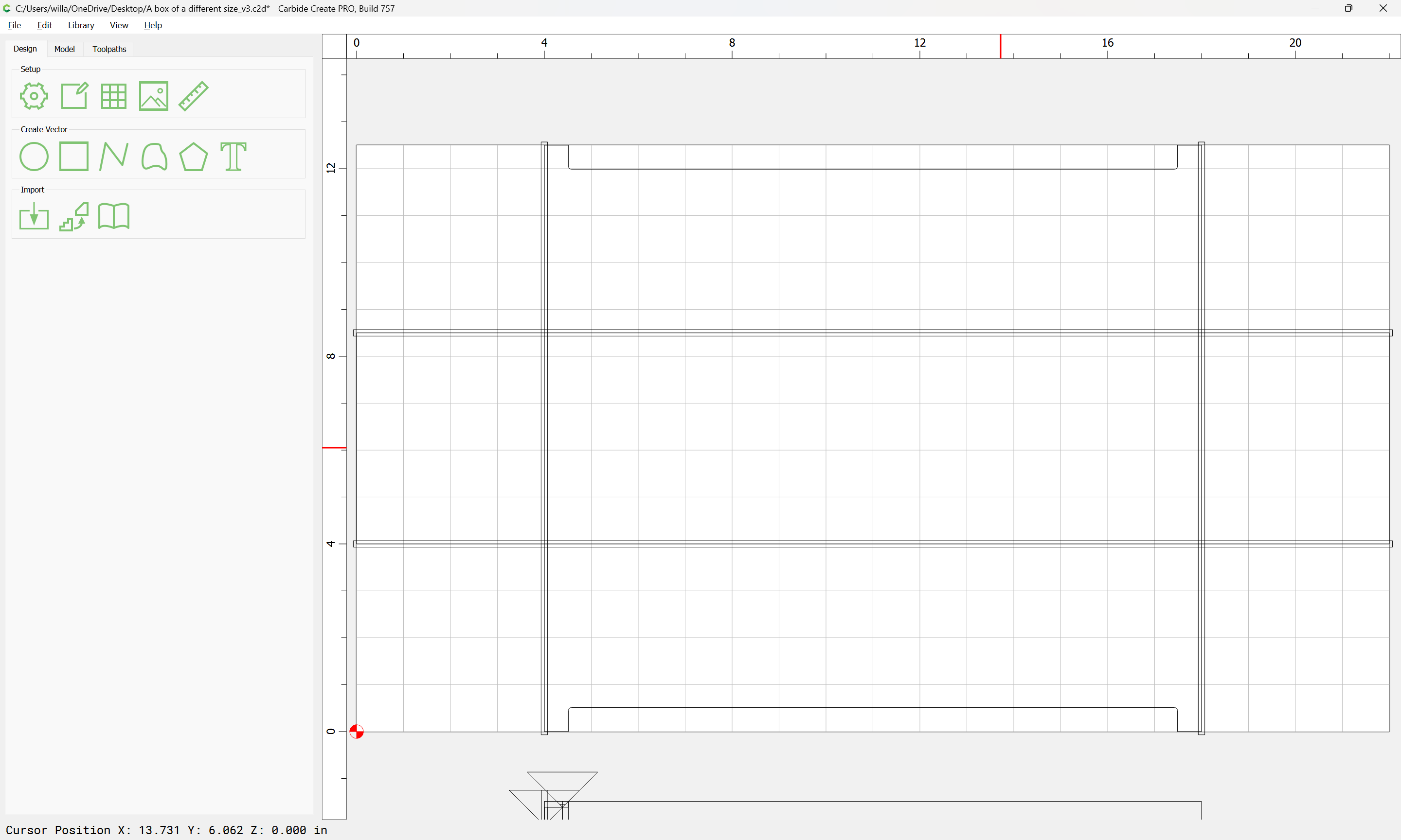
Decide where the large V endmill will stop cutting, and draw in the geometry for the joinery. At the ends it should be workable to cut less material, but there is also the consideration of the space needed for the holes for the hinges, but it will also be desirable to draw in geometry to cut the channels for the narrow V endmill. To make things easier to work with, we will not round off the corners, leaving that to the toolpath visualization.

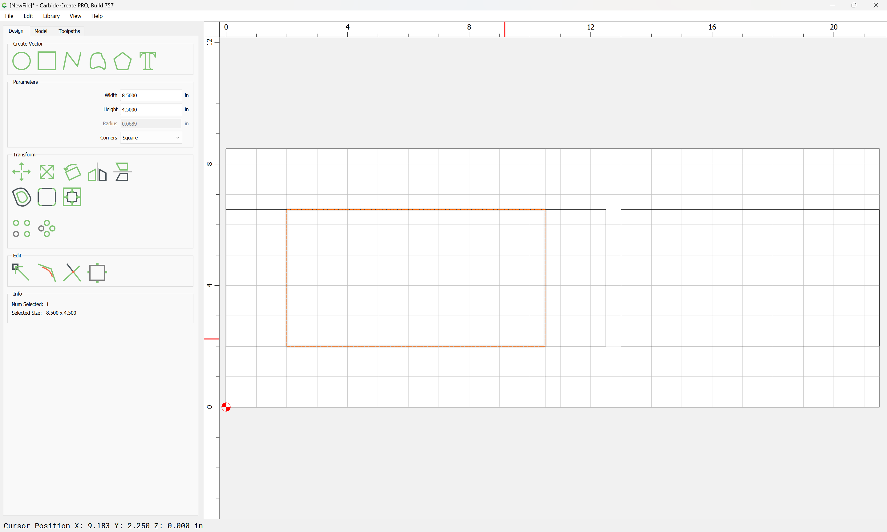
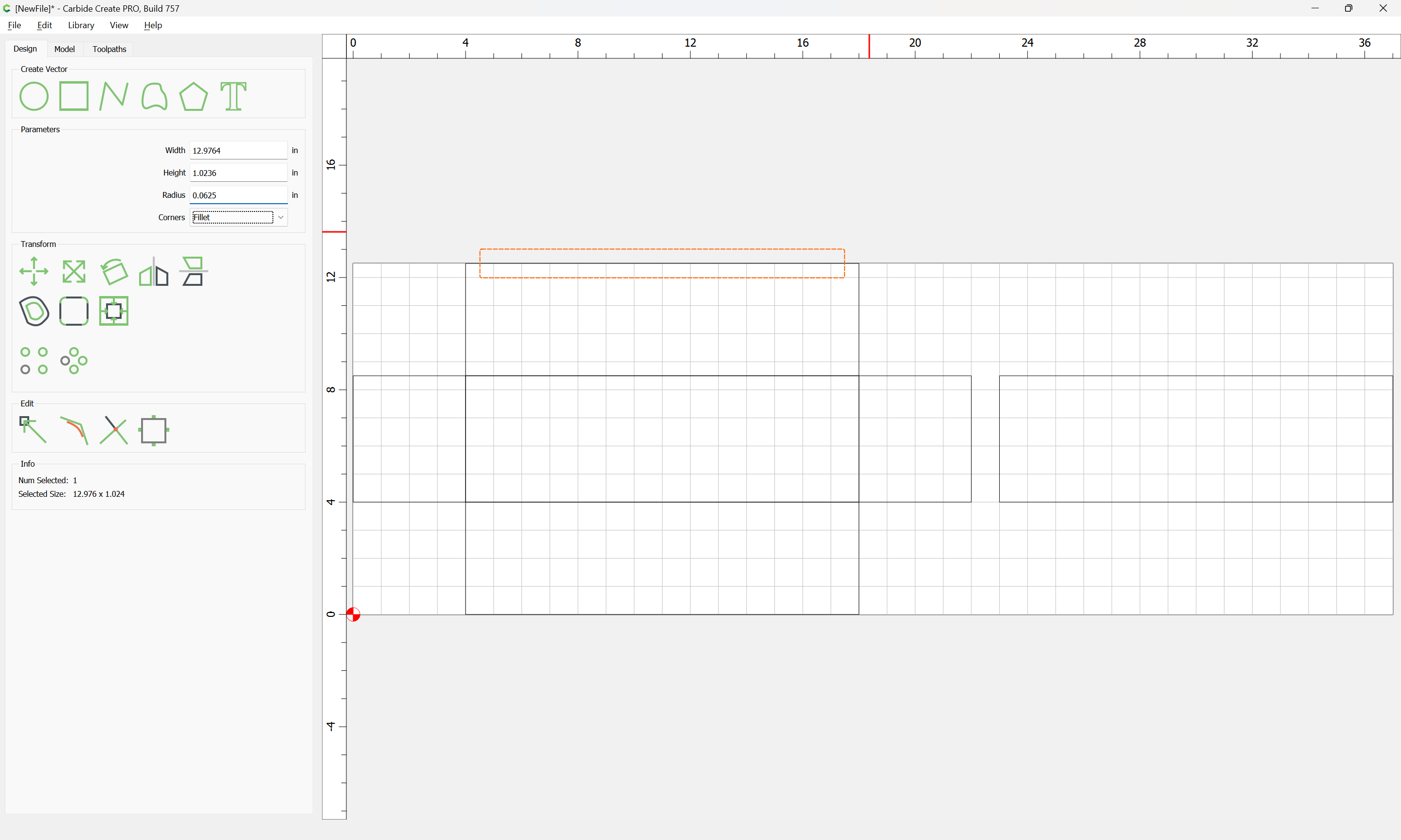
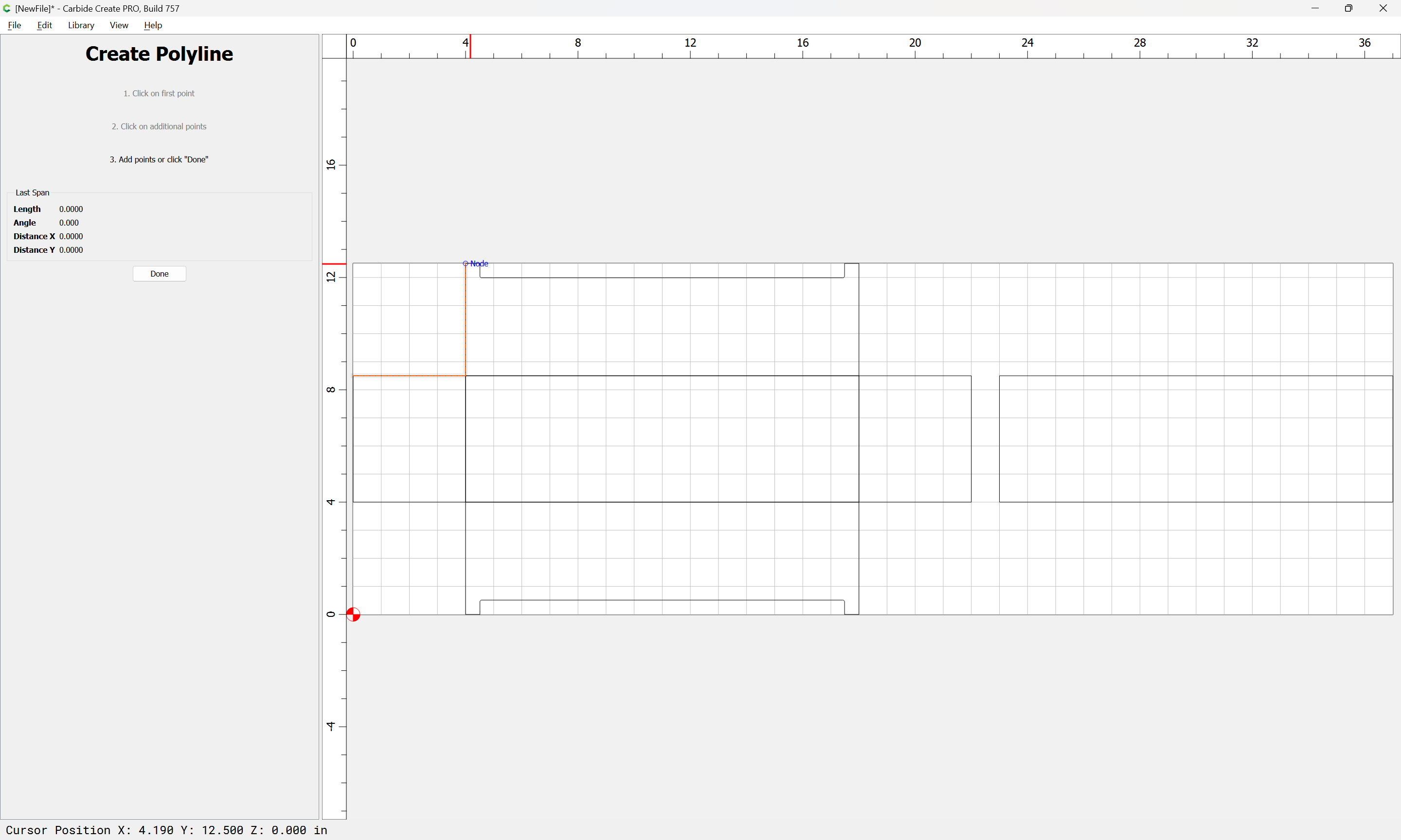
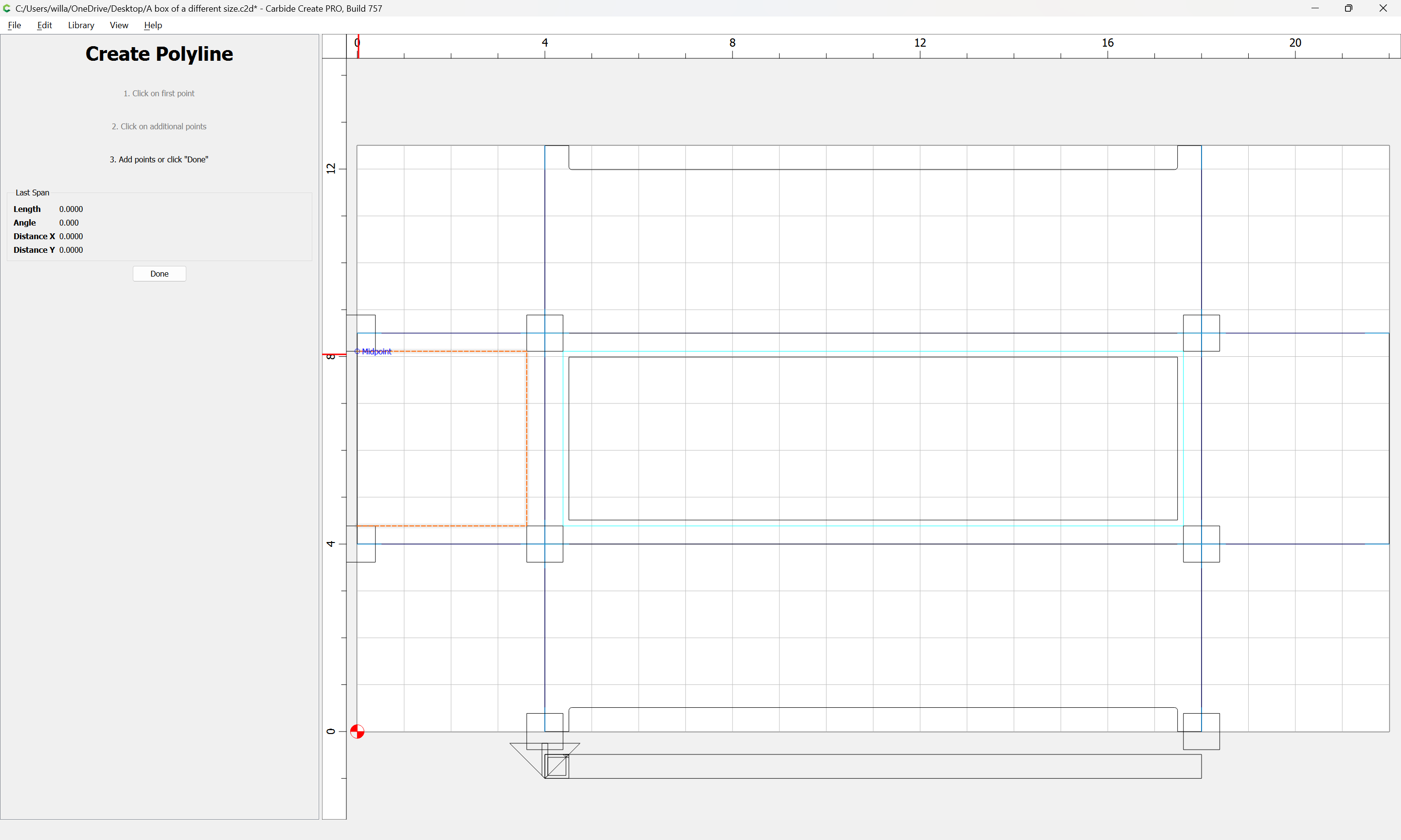
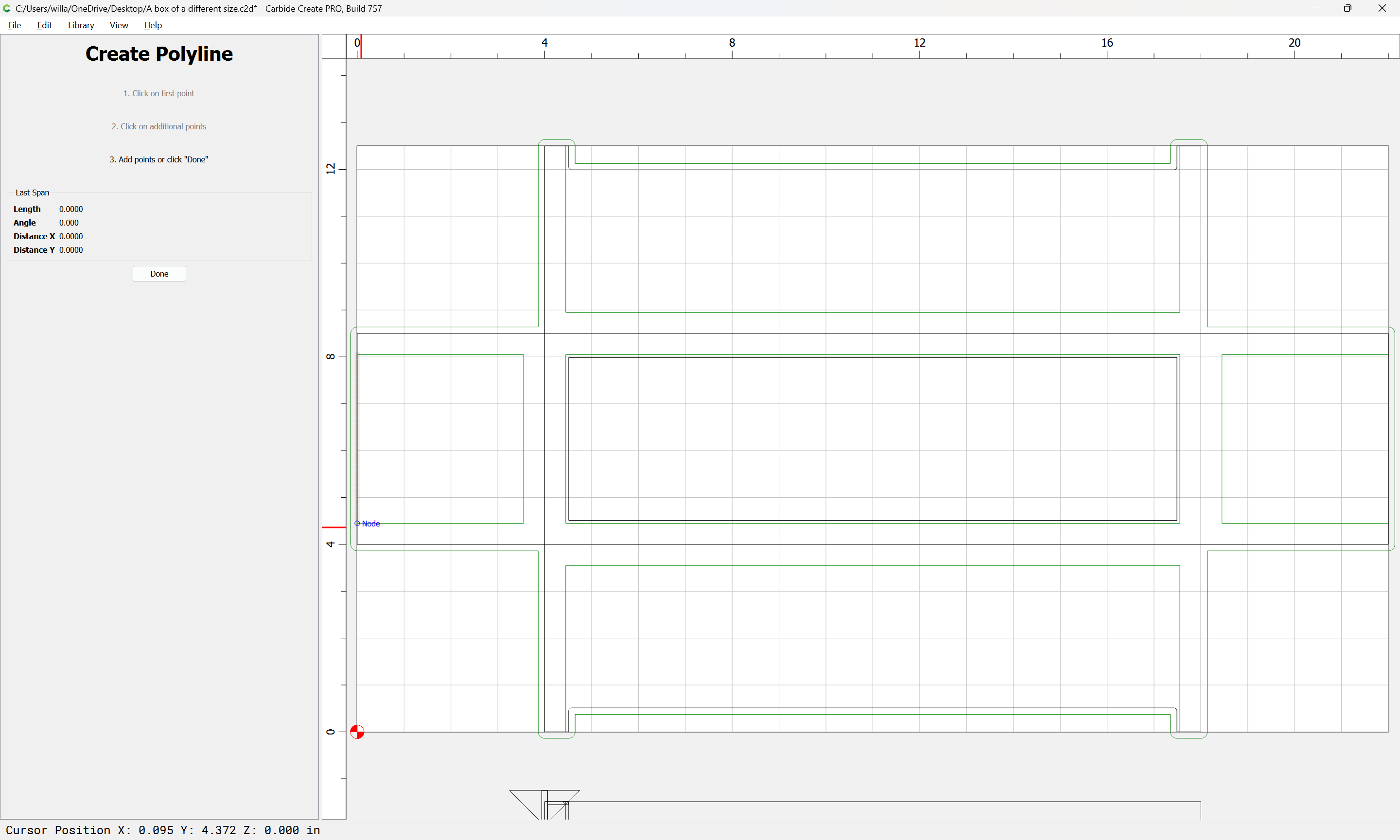
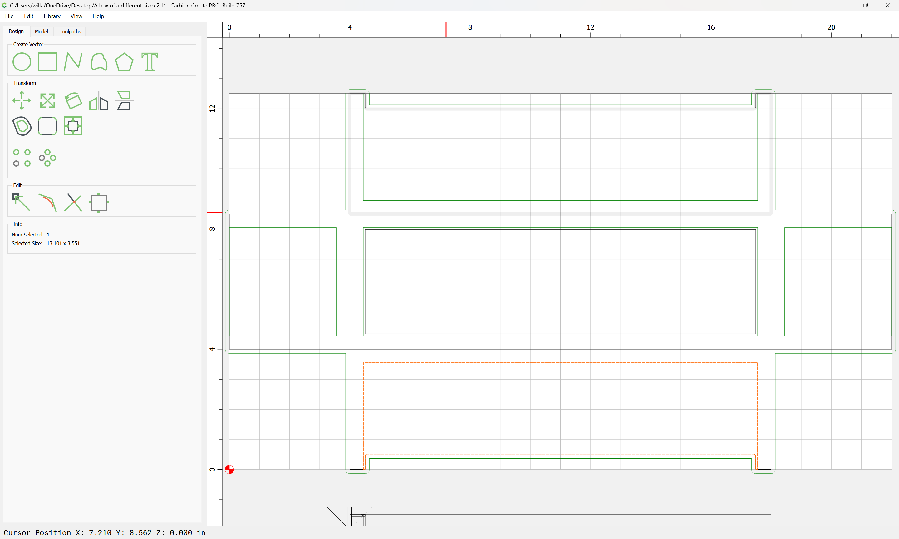
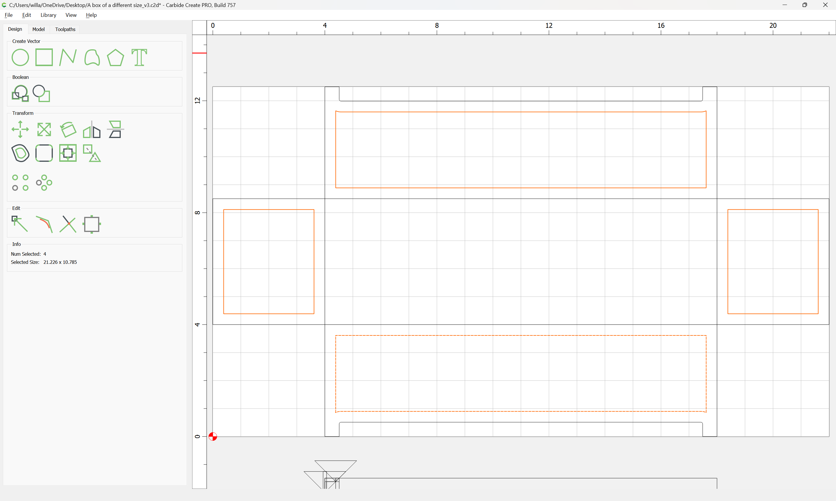
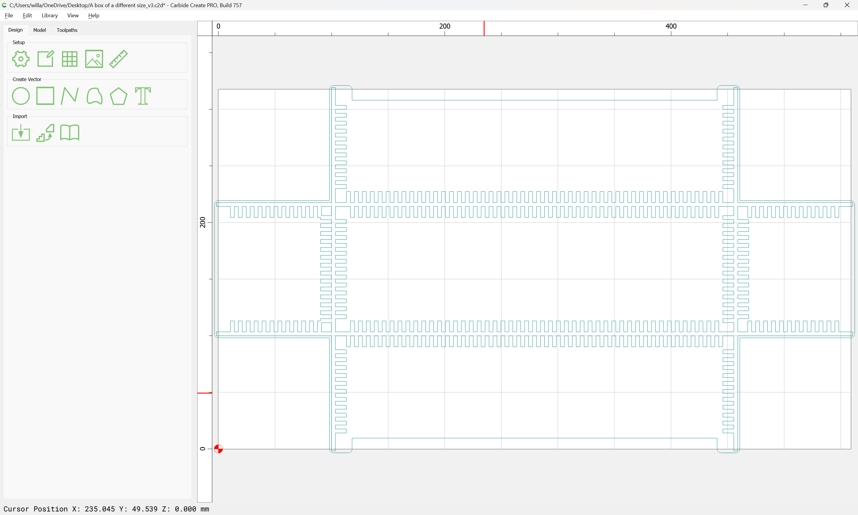
First, draw the channels:

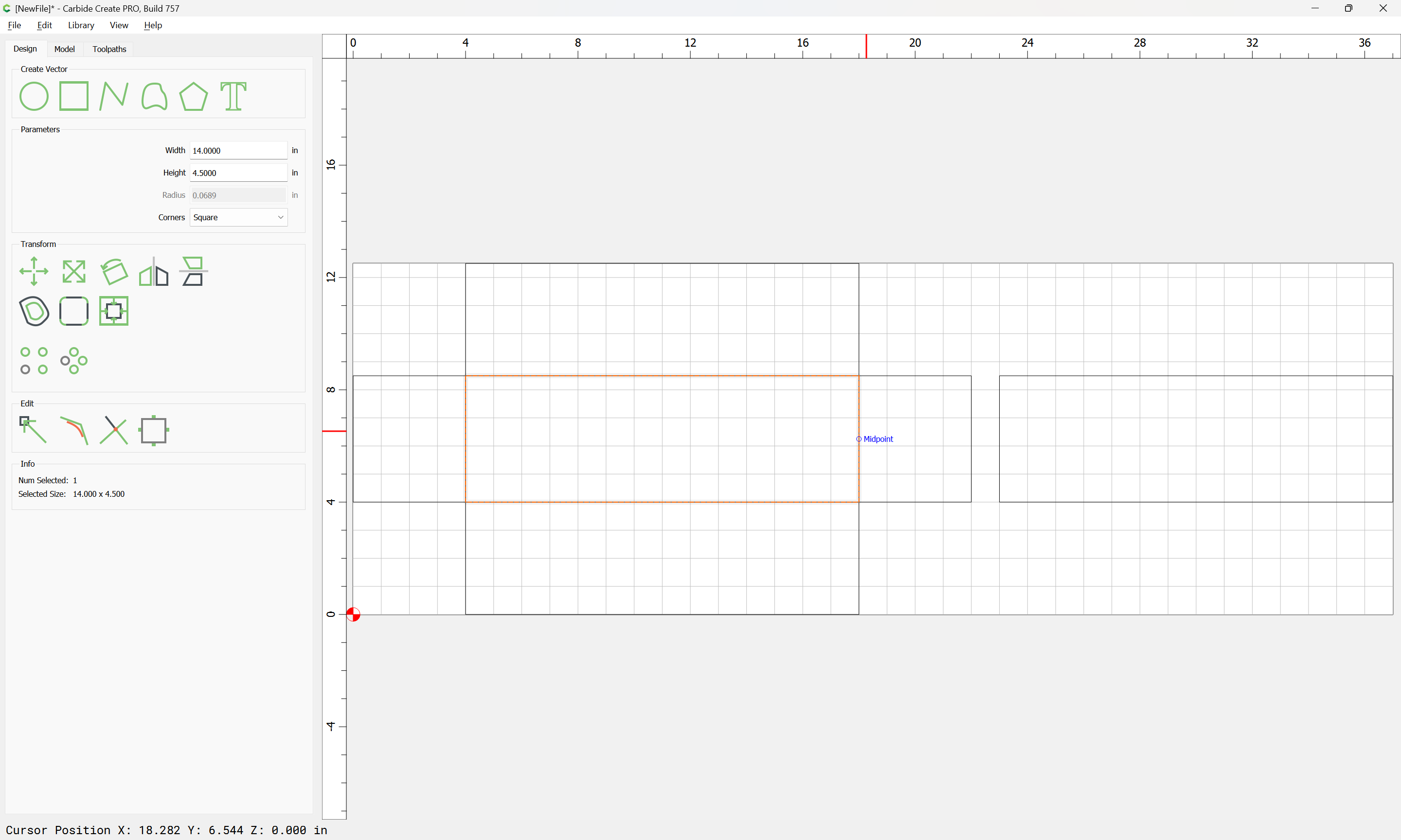
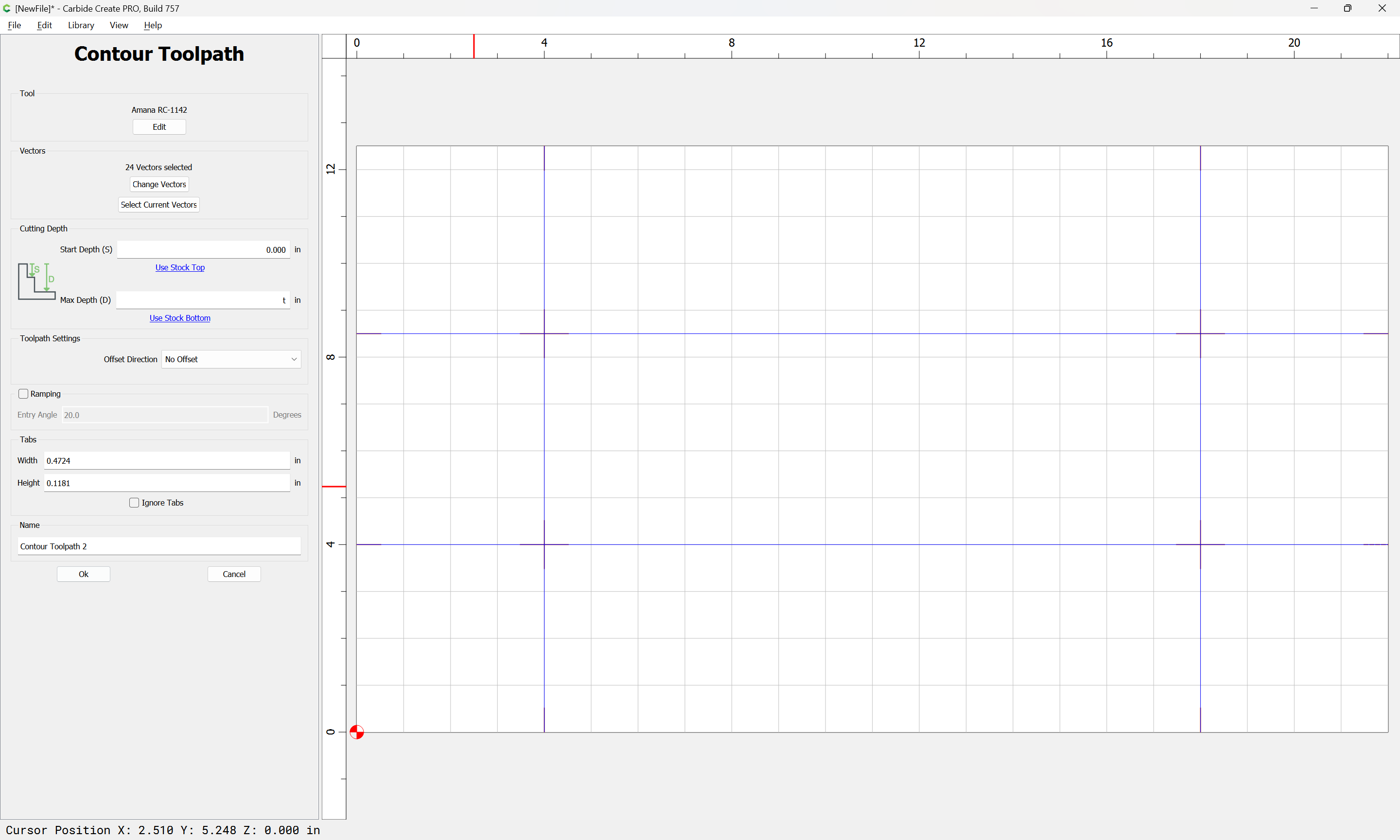
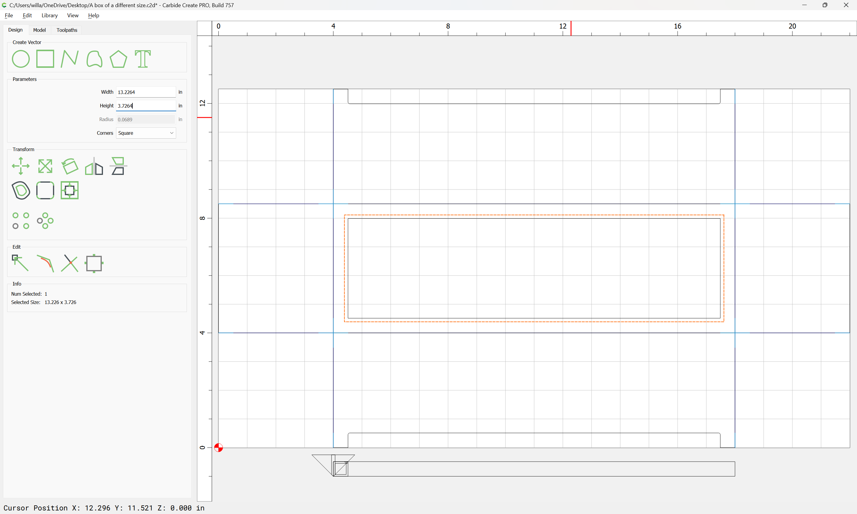
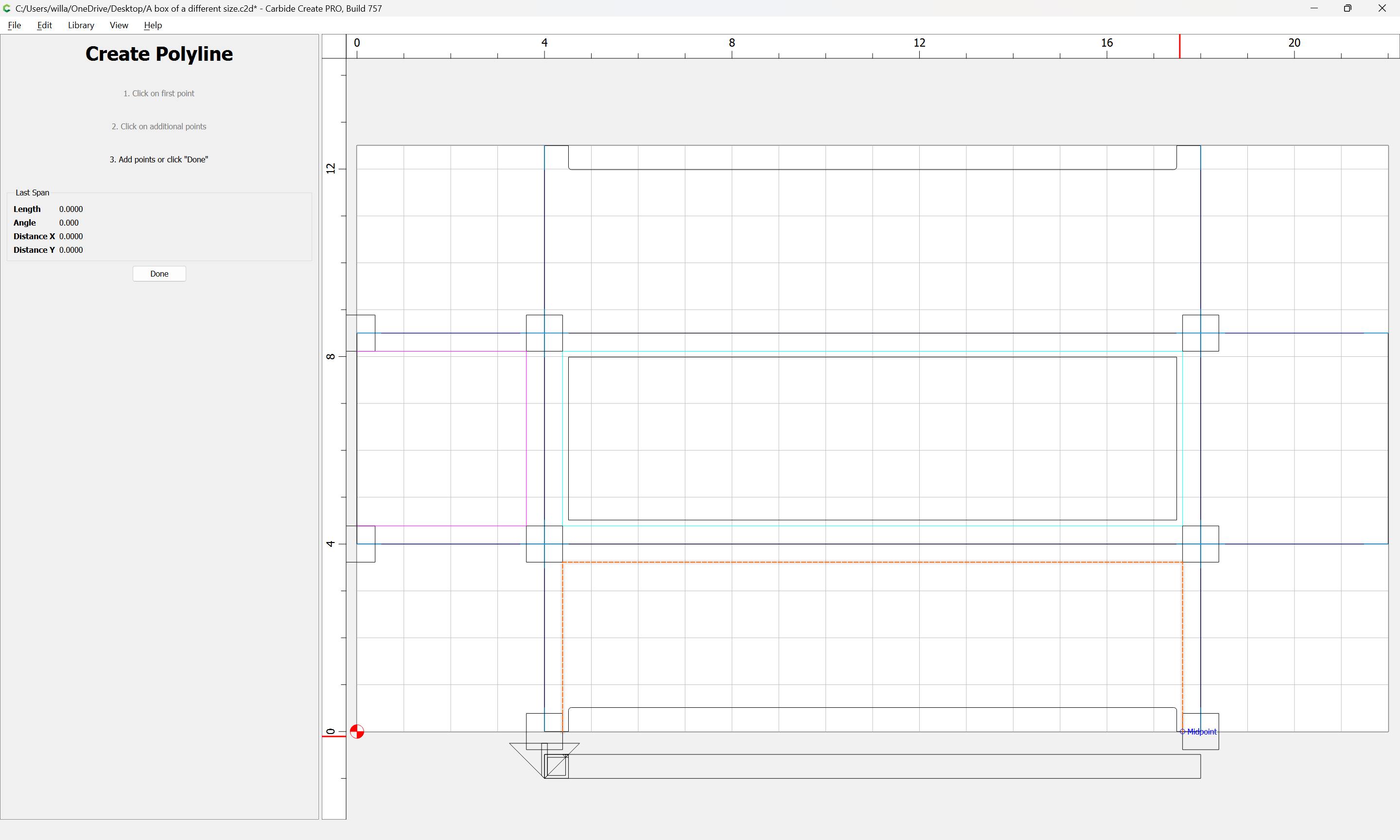
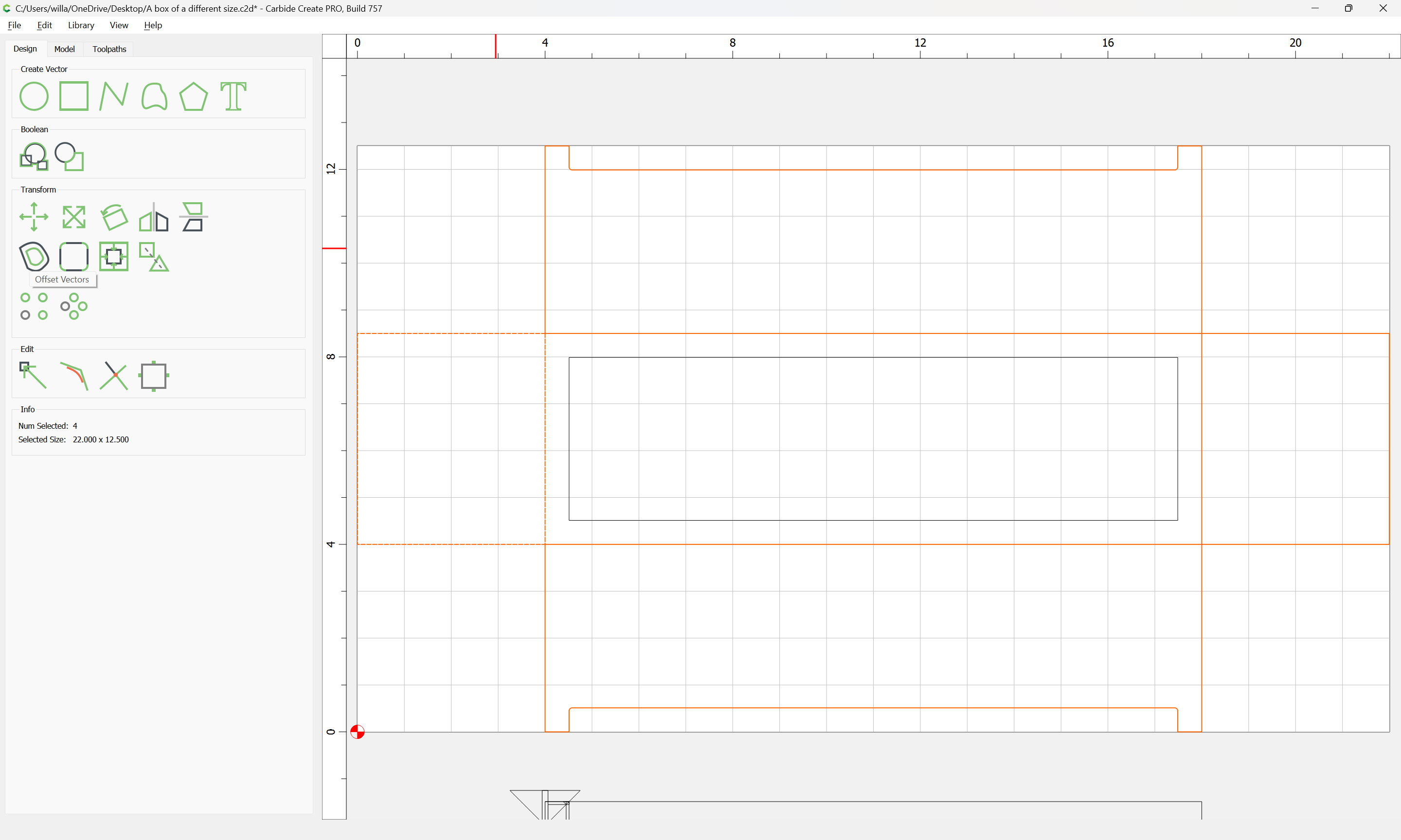
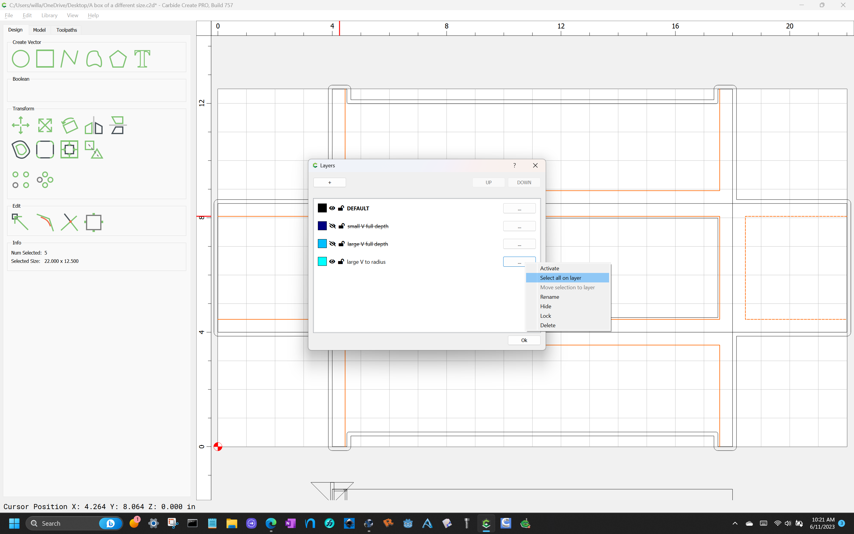
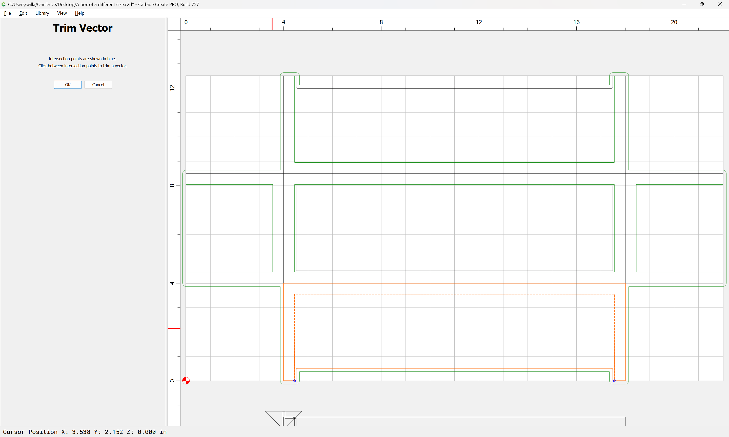
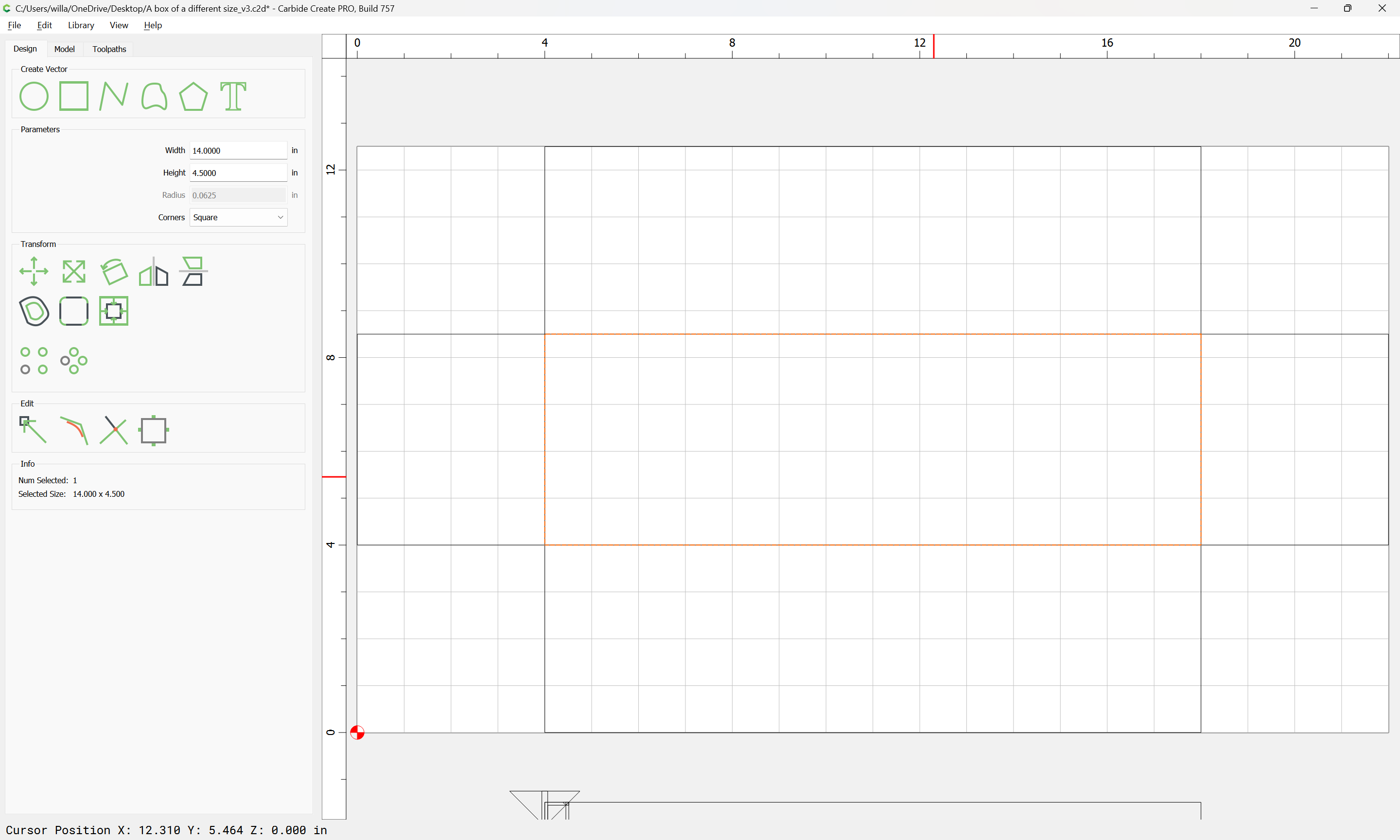
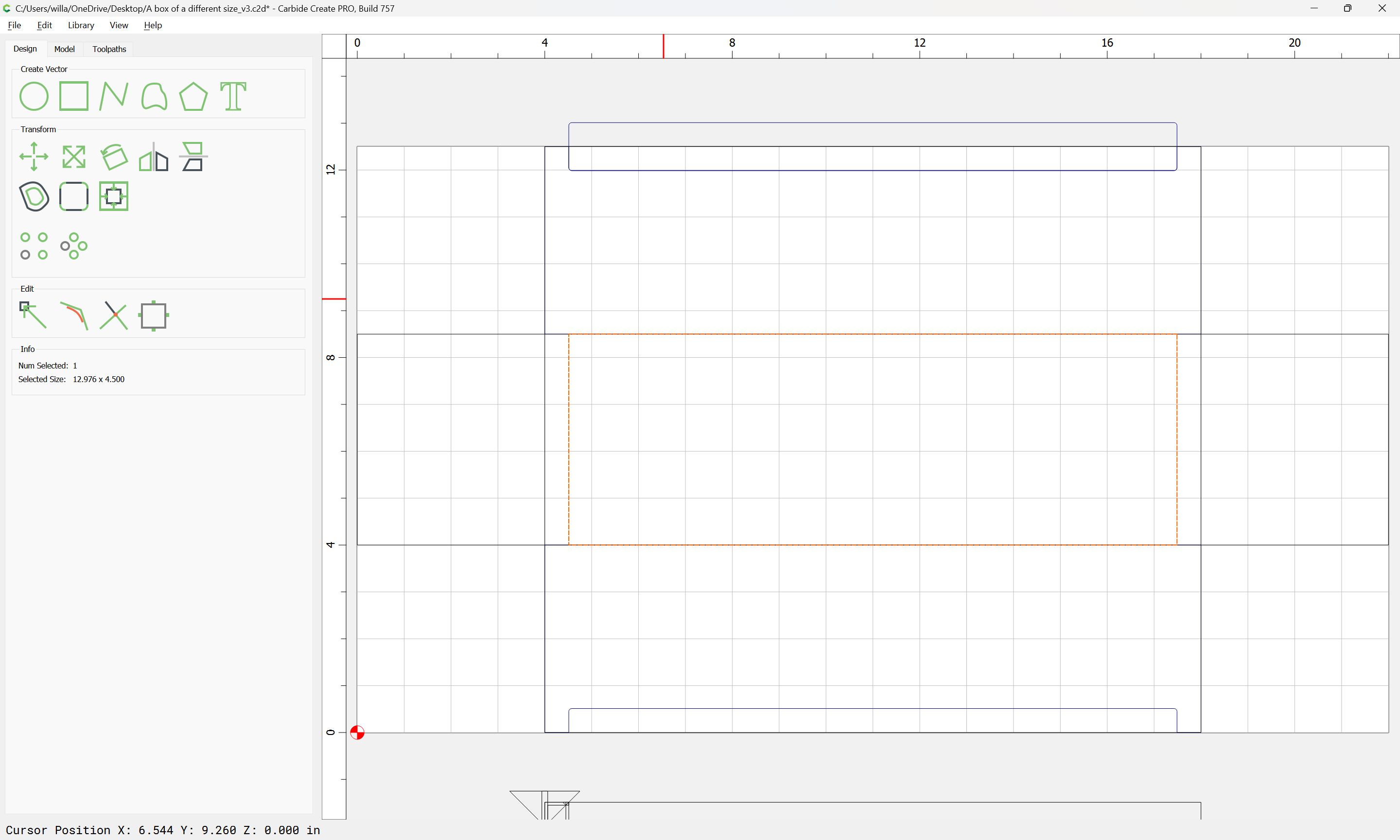
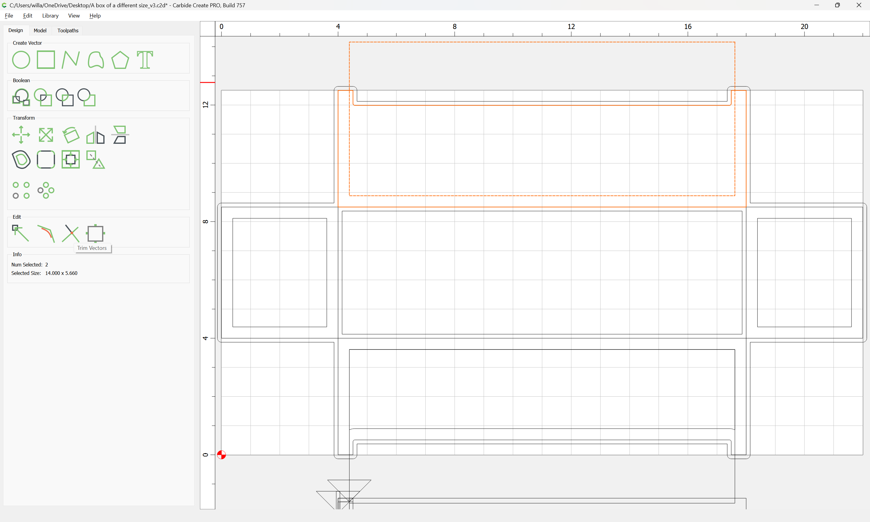
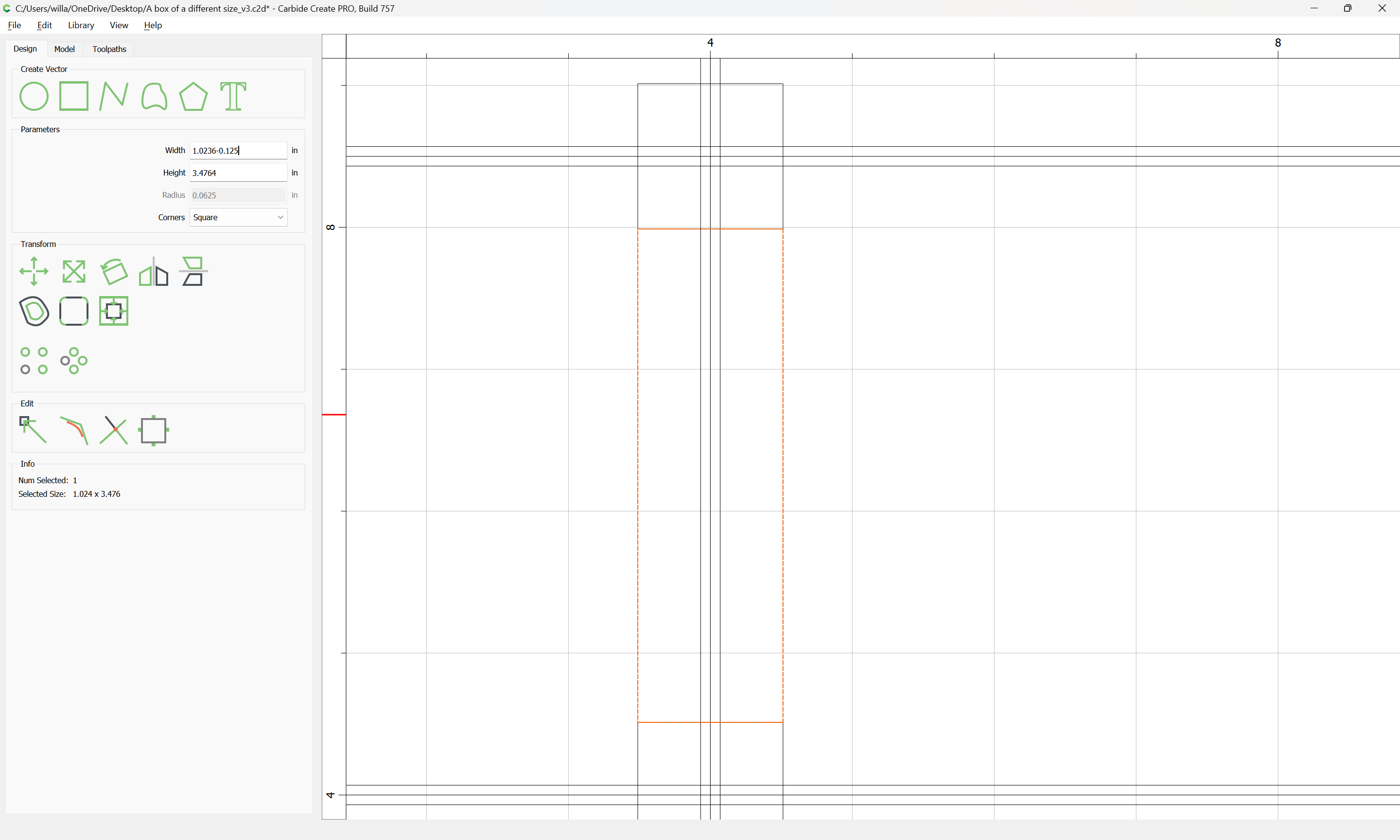
Then draw in where the V endmill toolpaths will begin/end — to simplify this, just use the stock width everywhere:

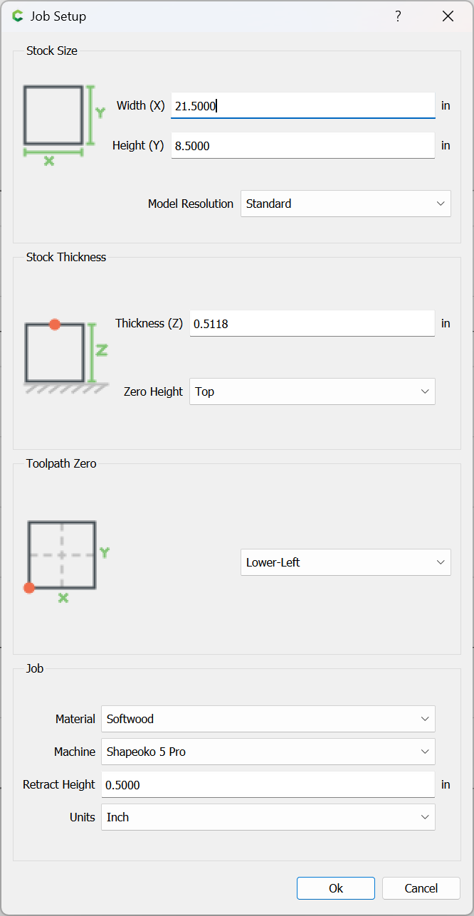
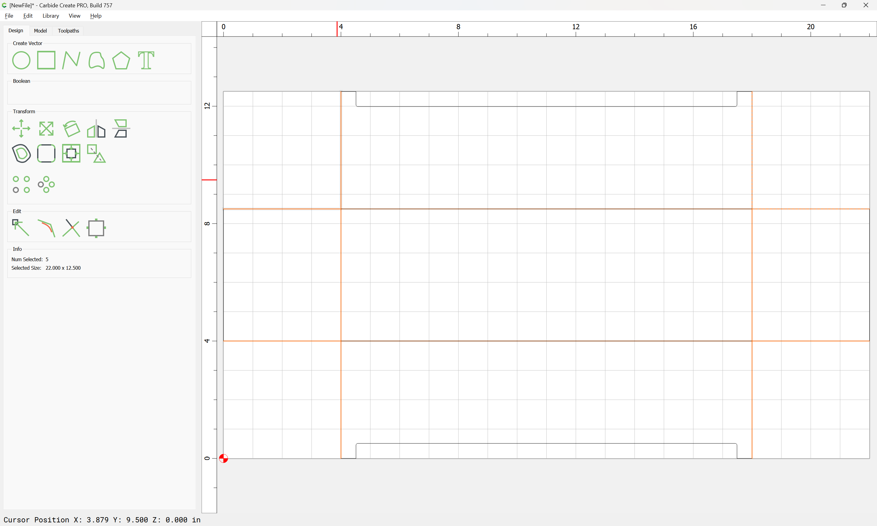
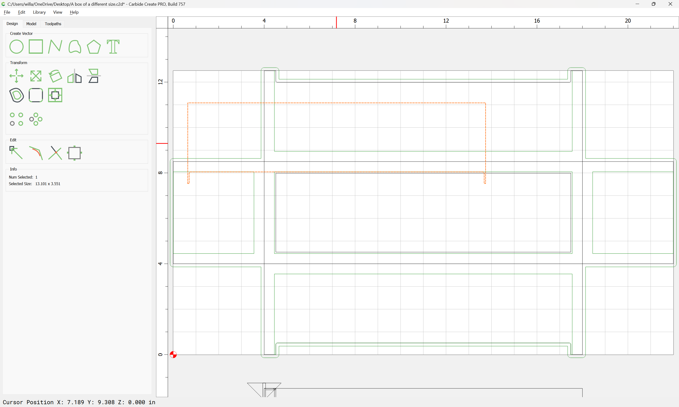
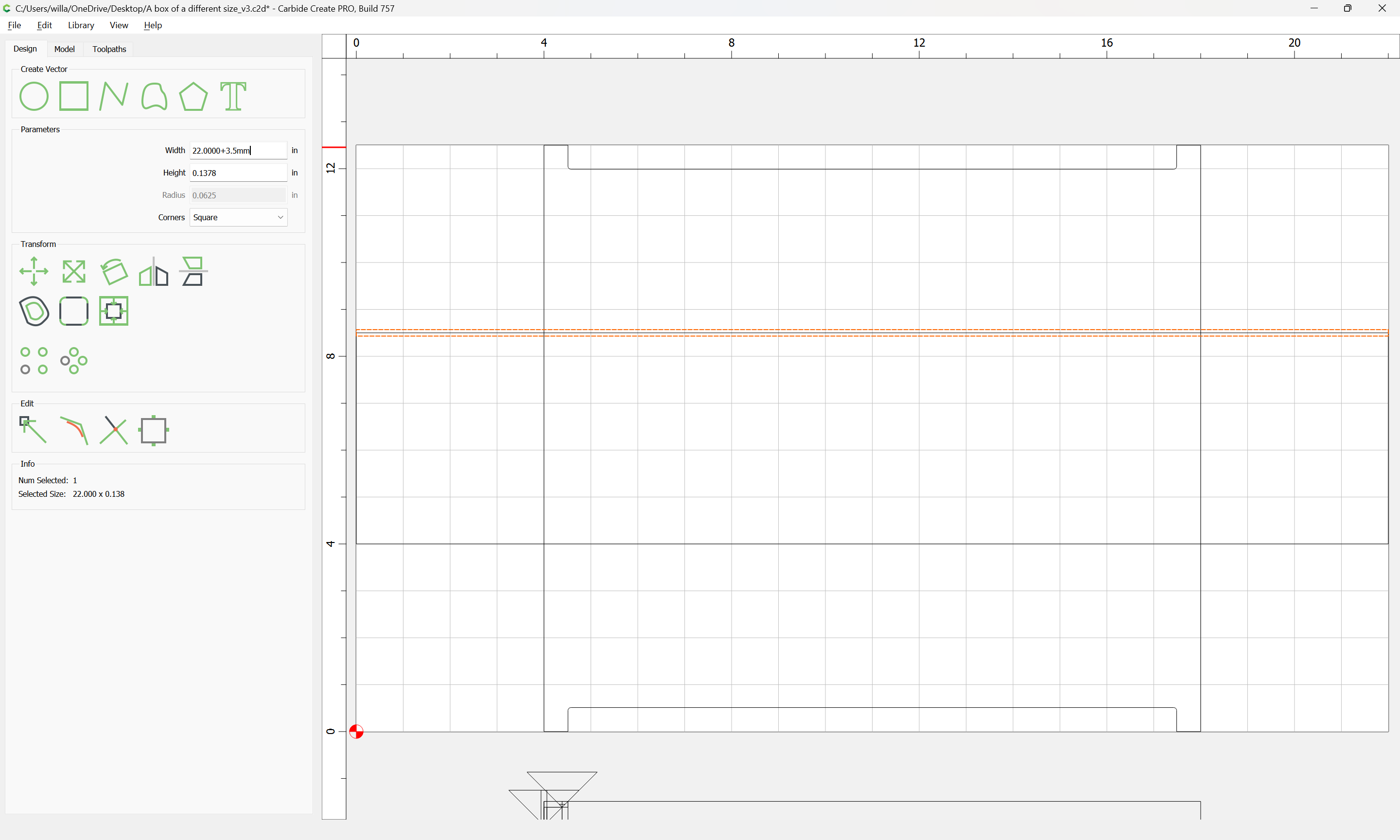
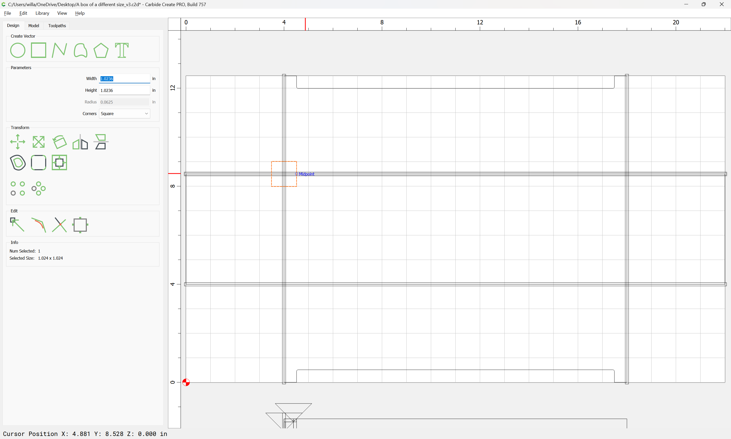
Using this dimension has the advantage of making it obvious where the stock will be when rotated, so a section of the joint can be described w/ one or two rectangles:

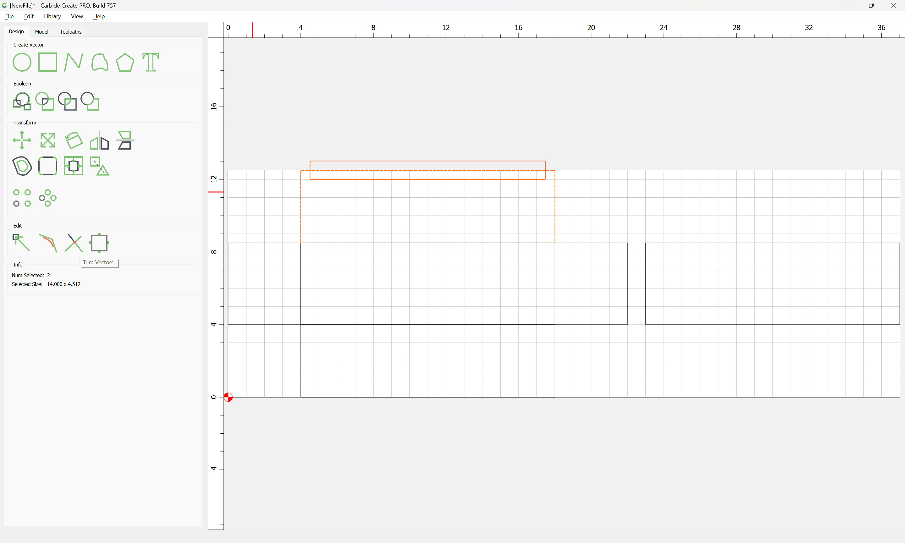
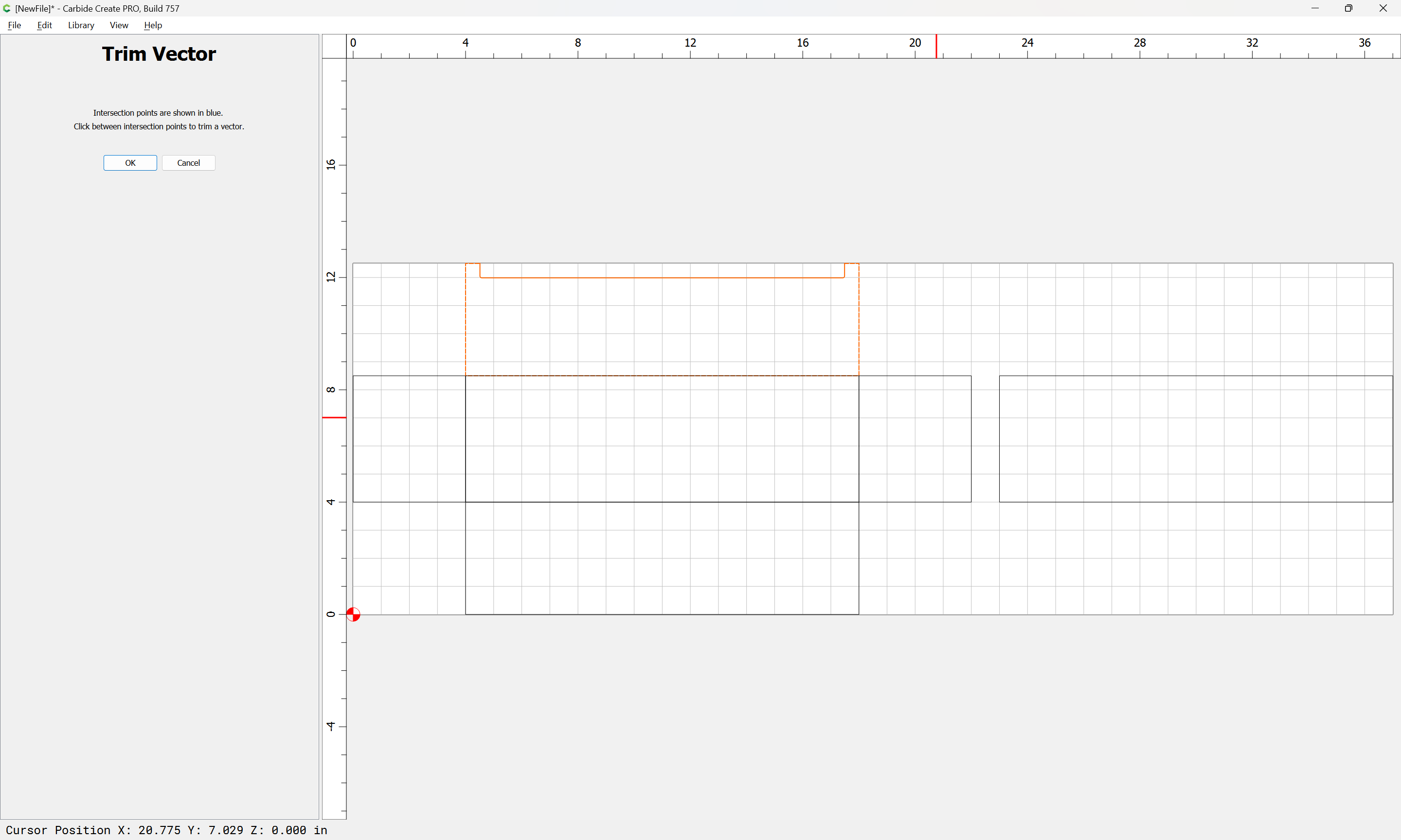
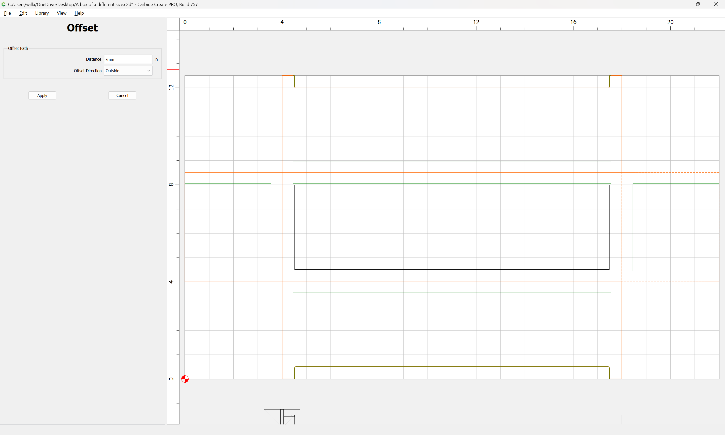
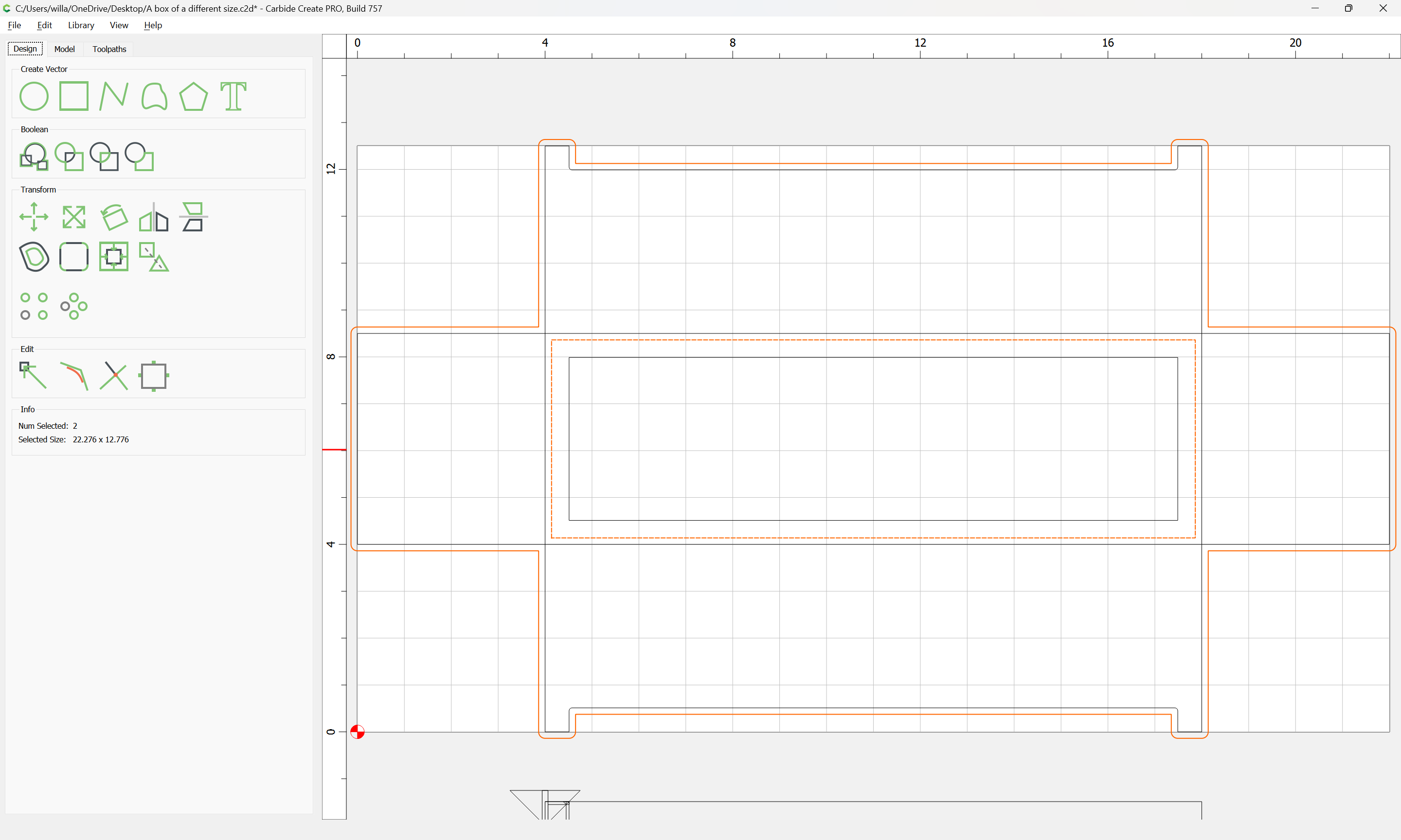
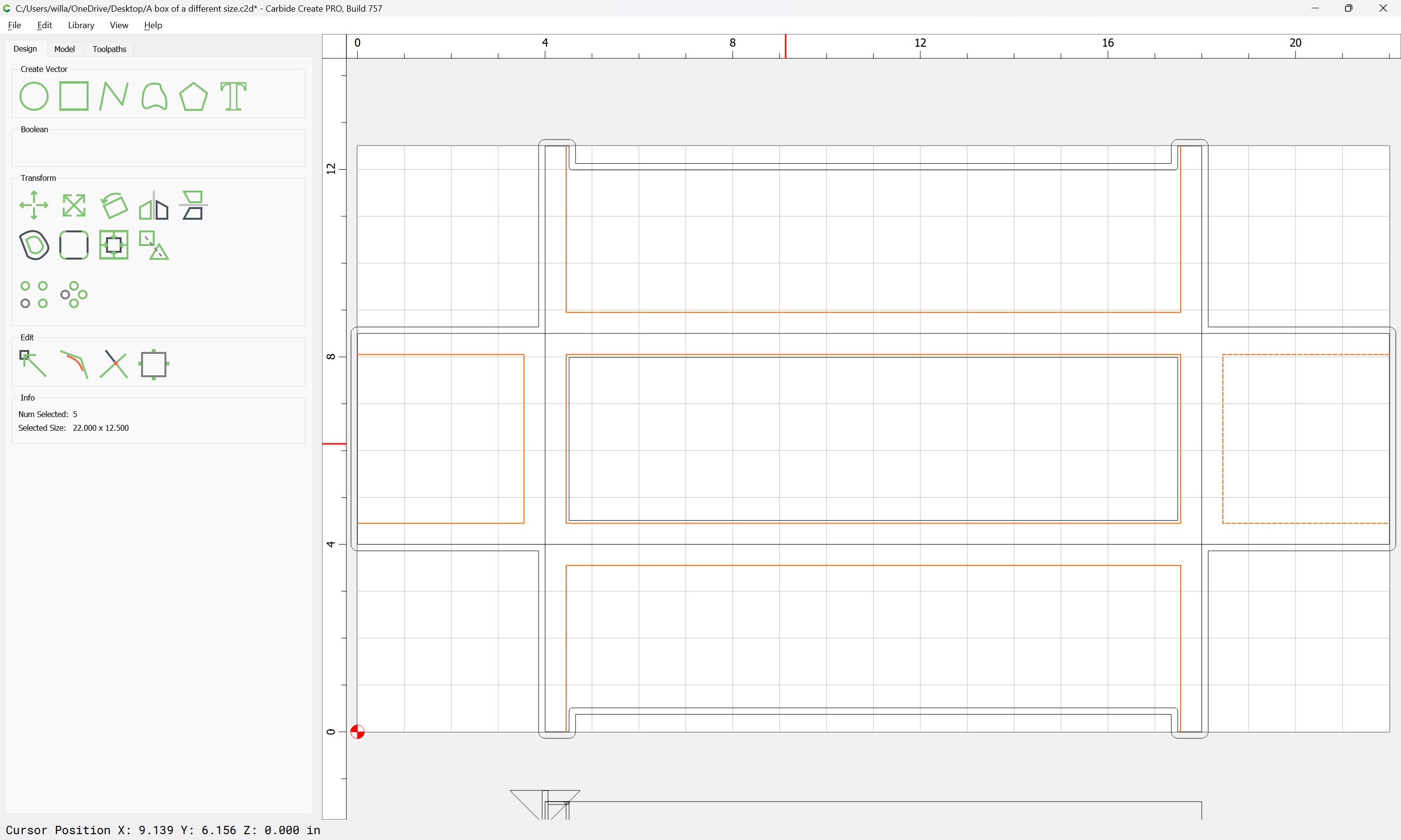
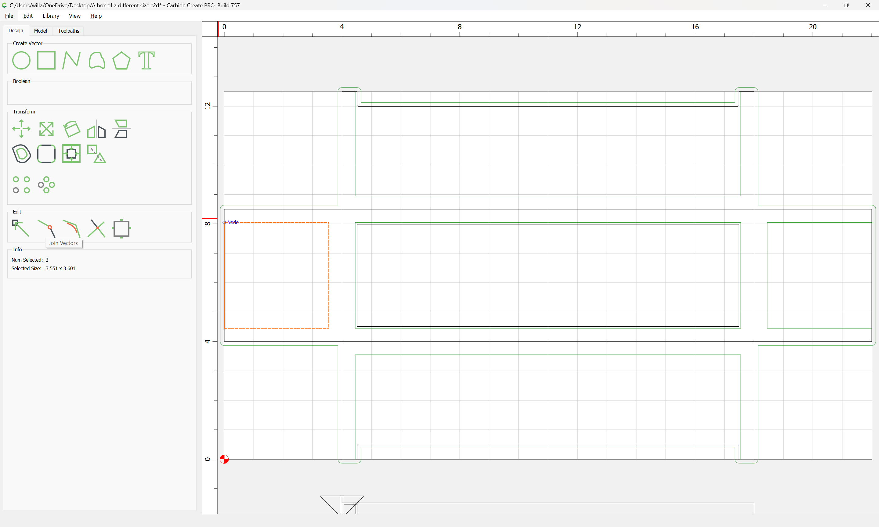
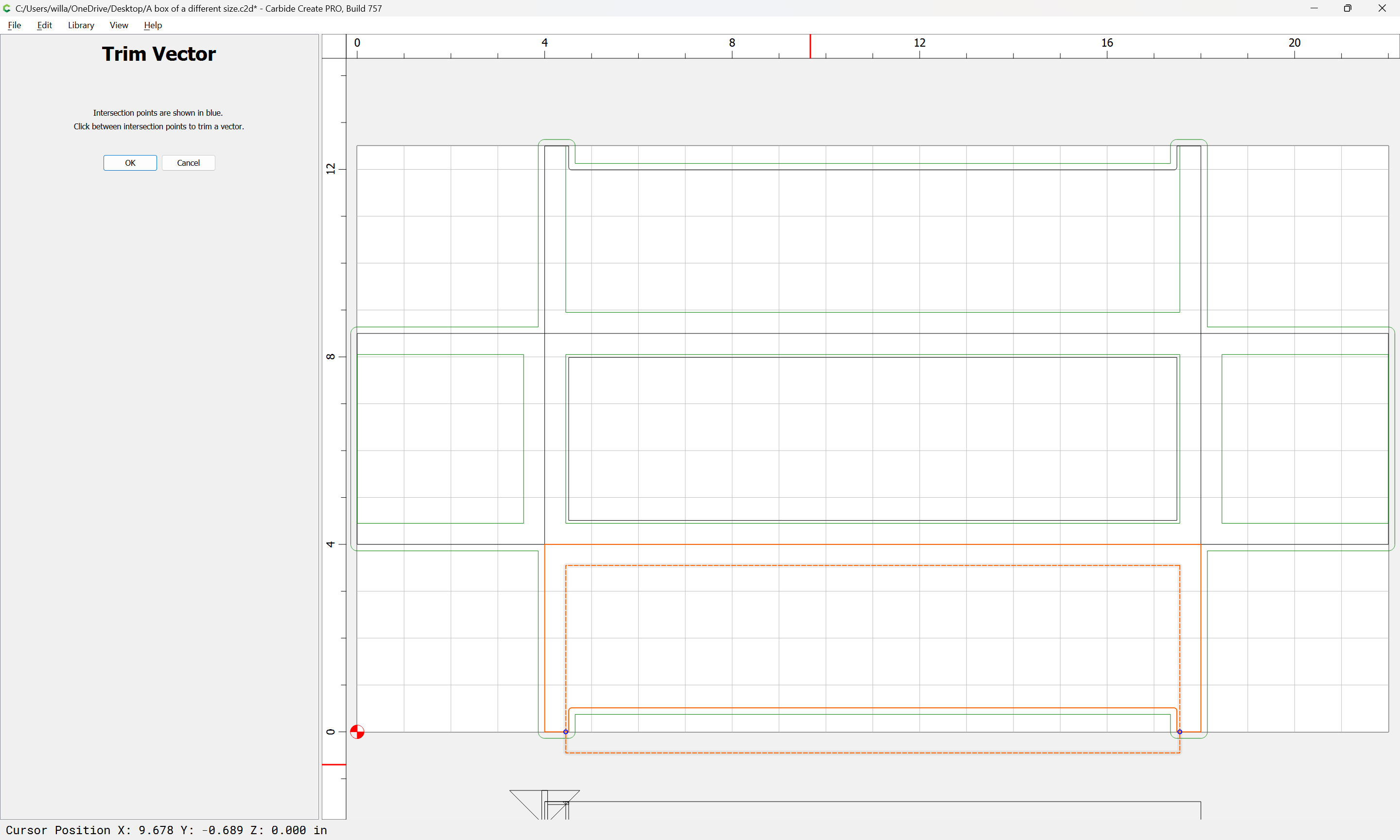
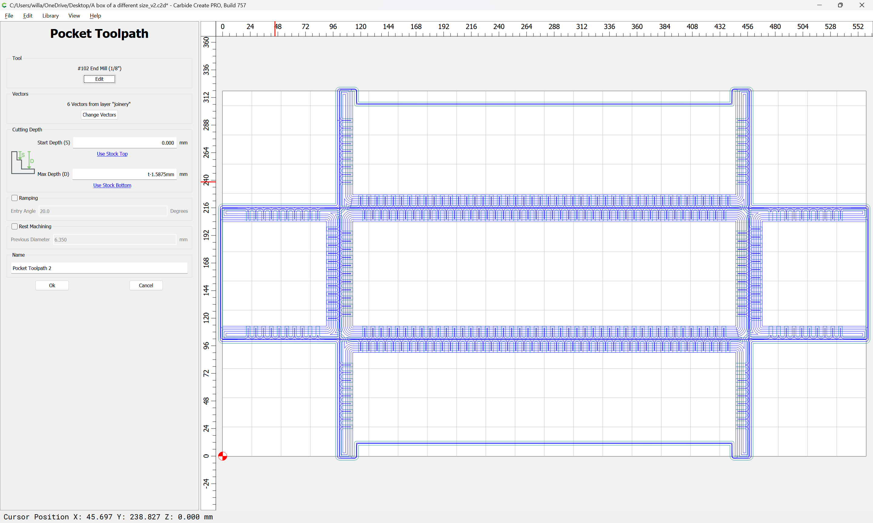
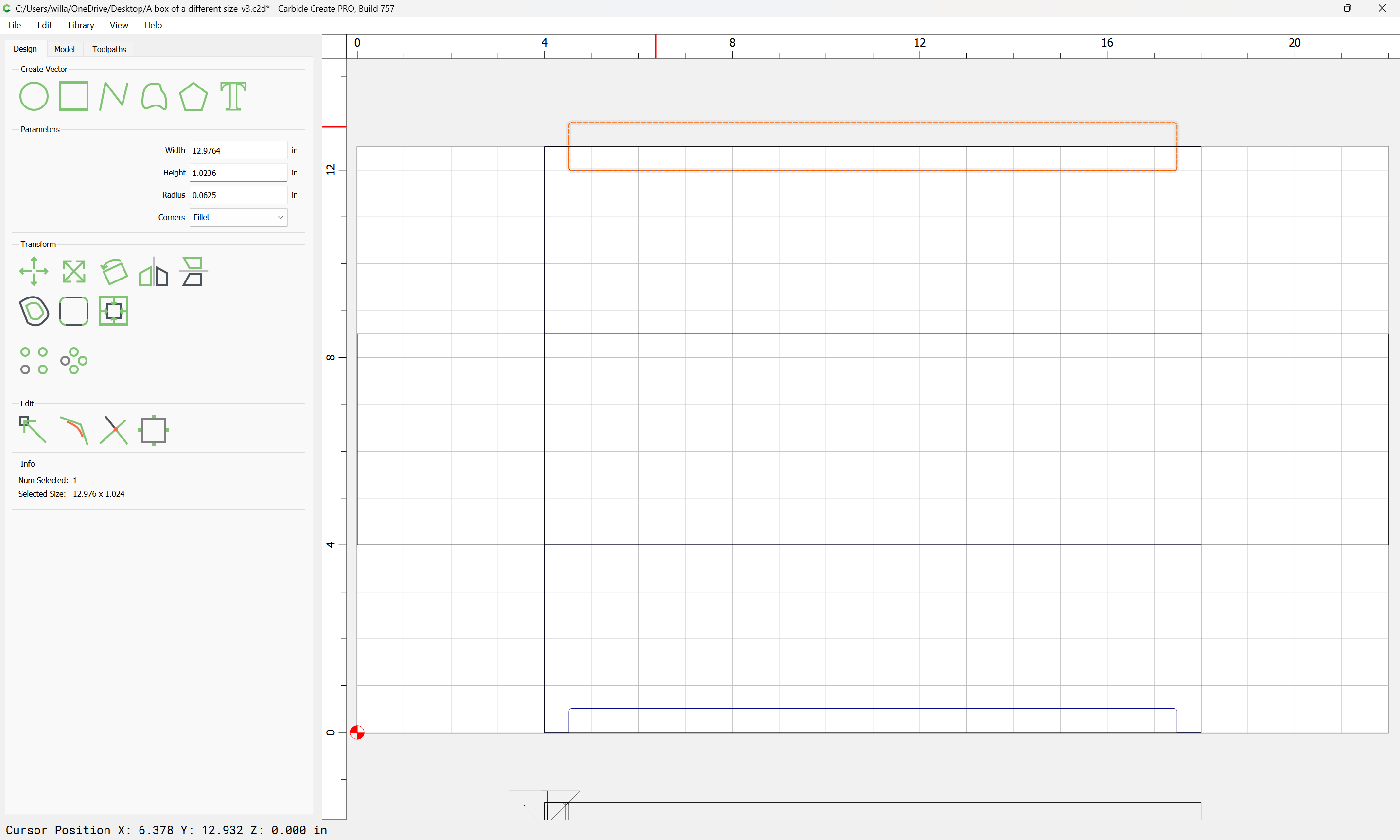
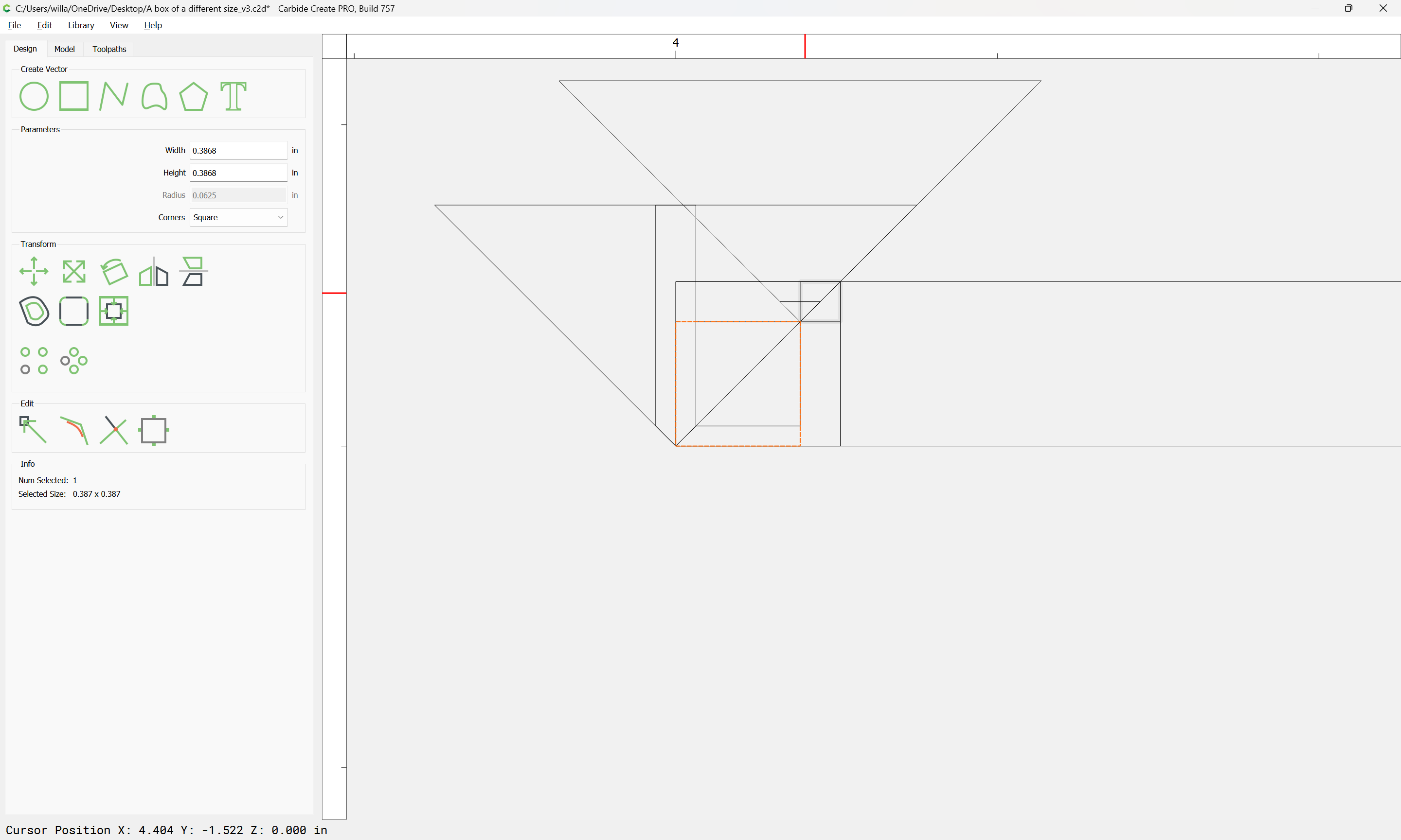
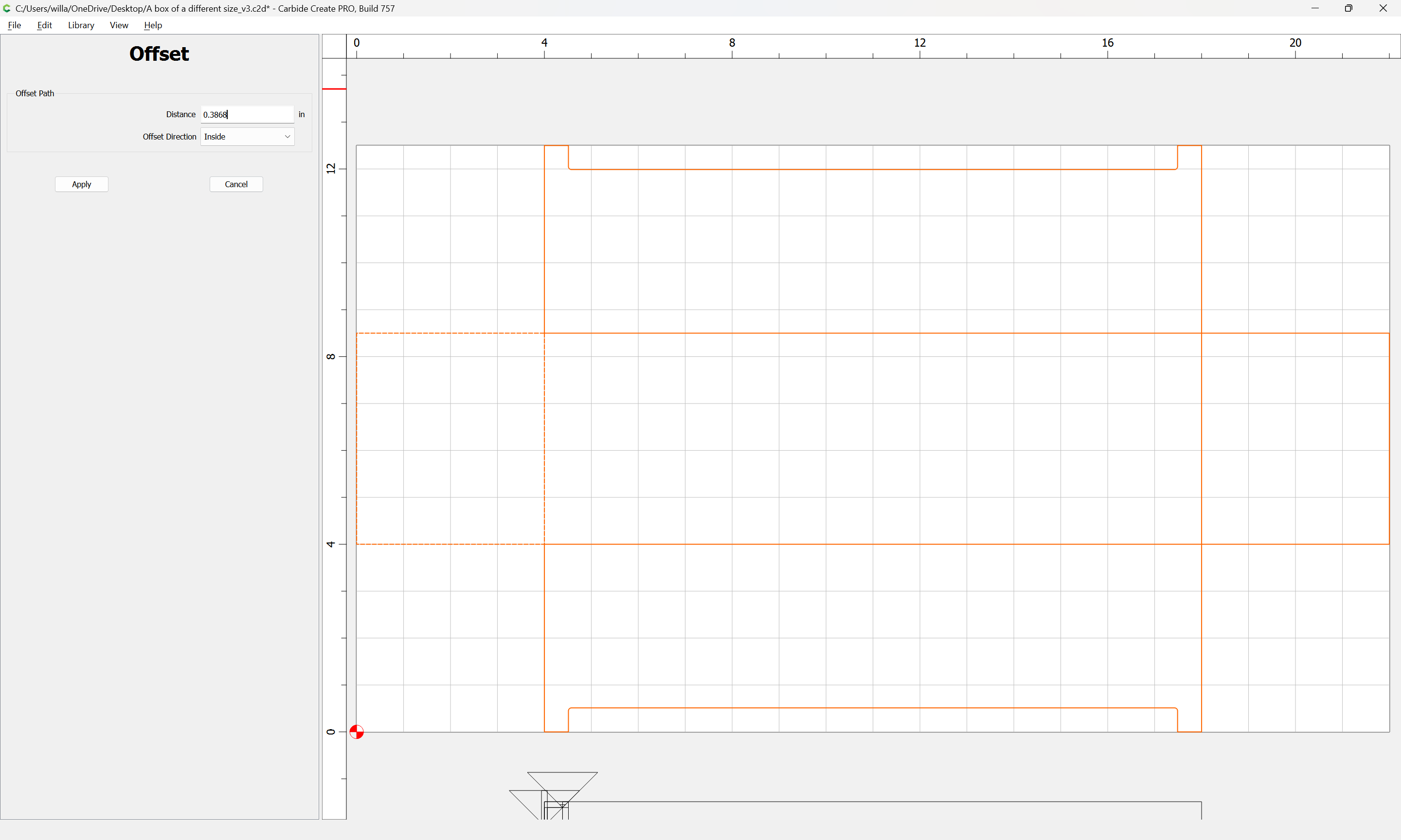
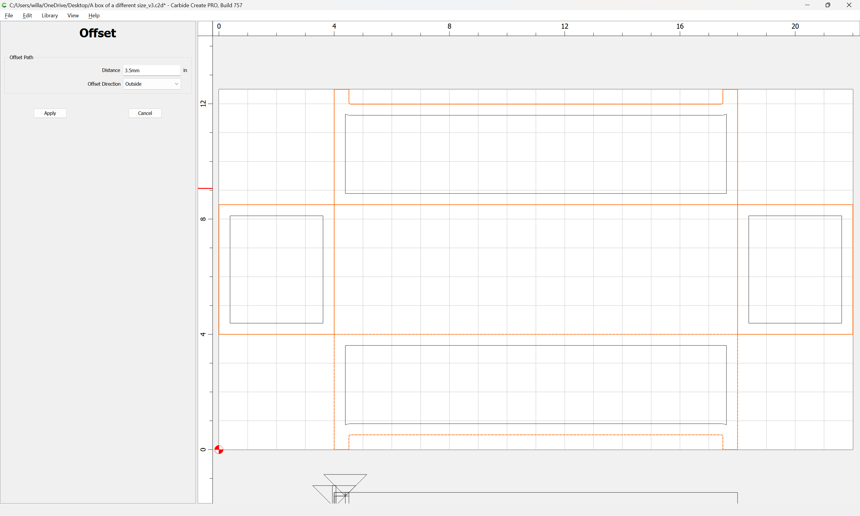
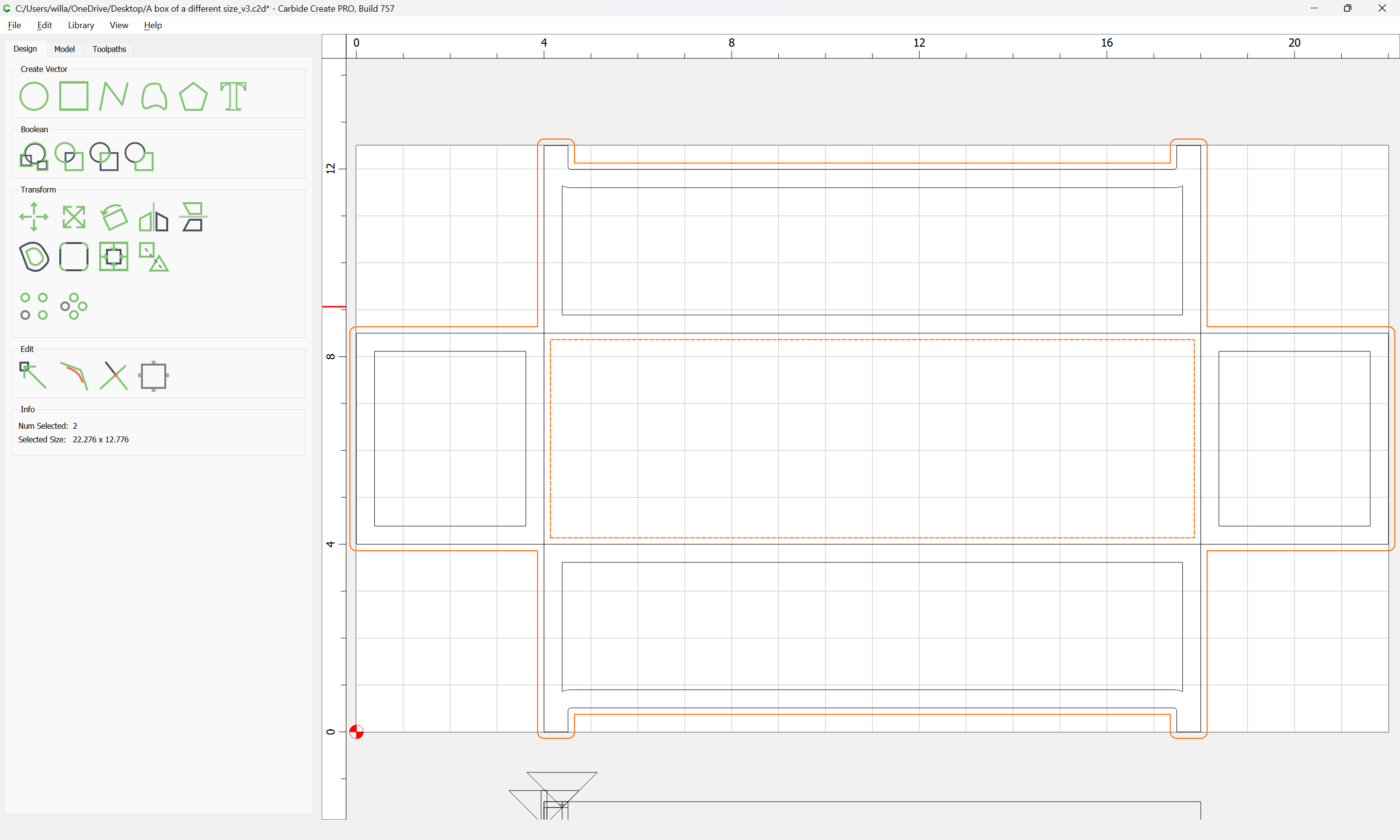
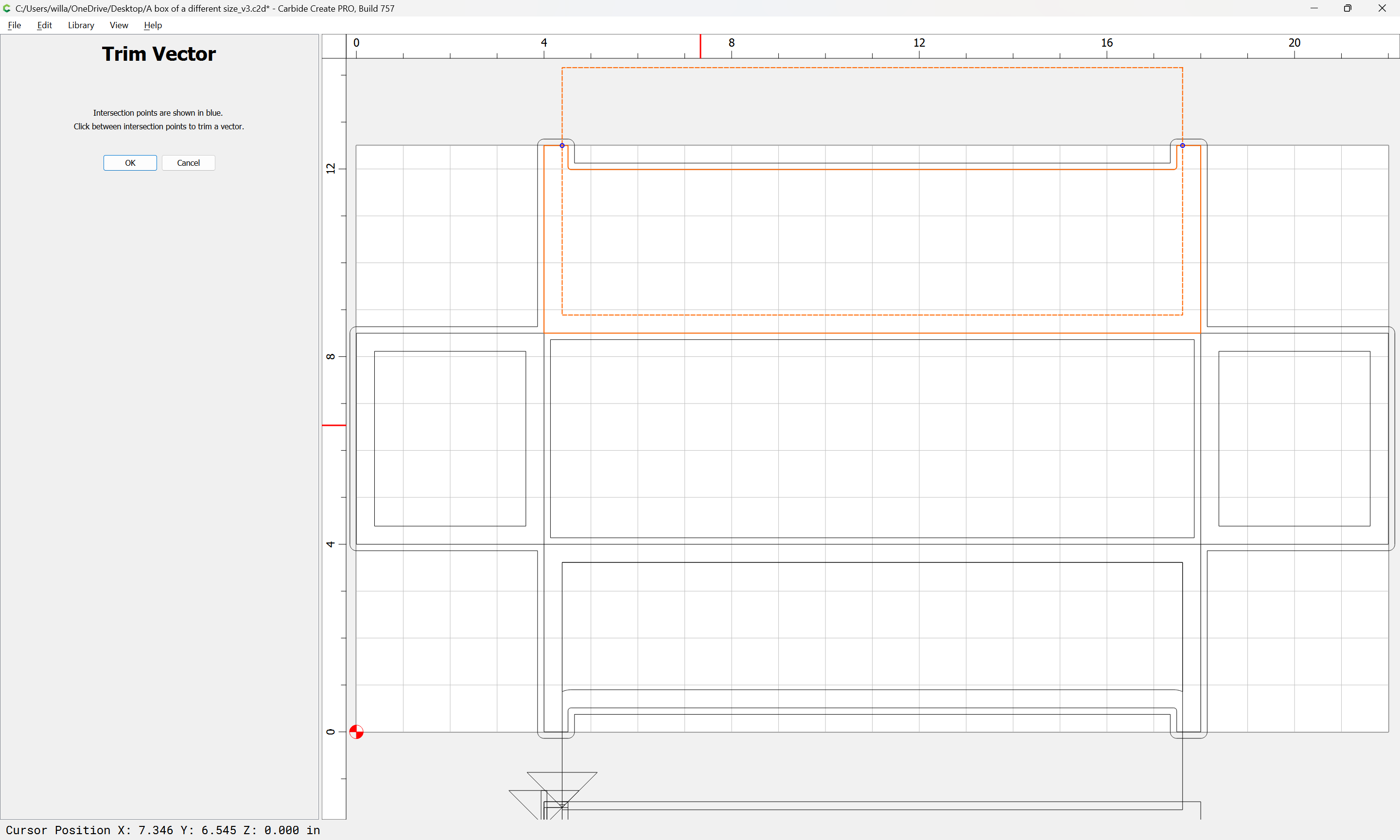
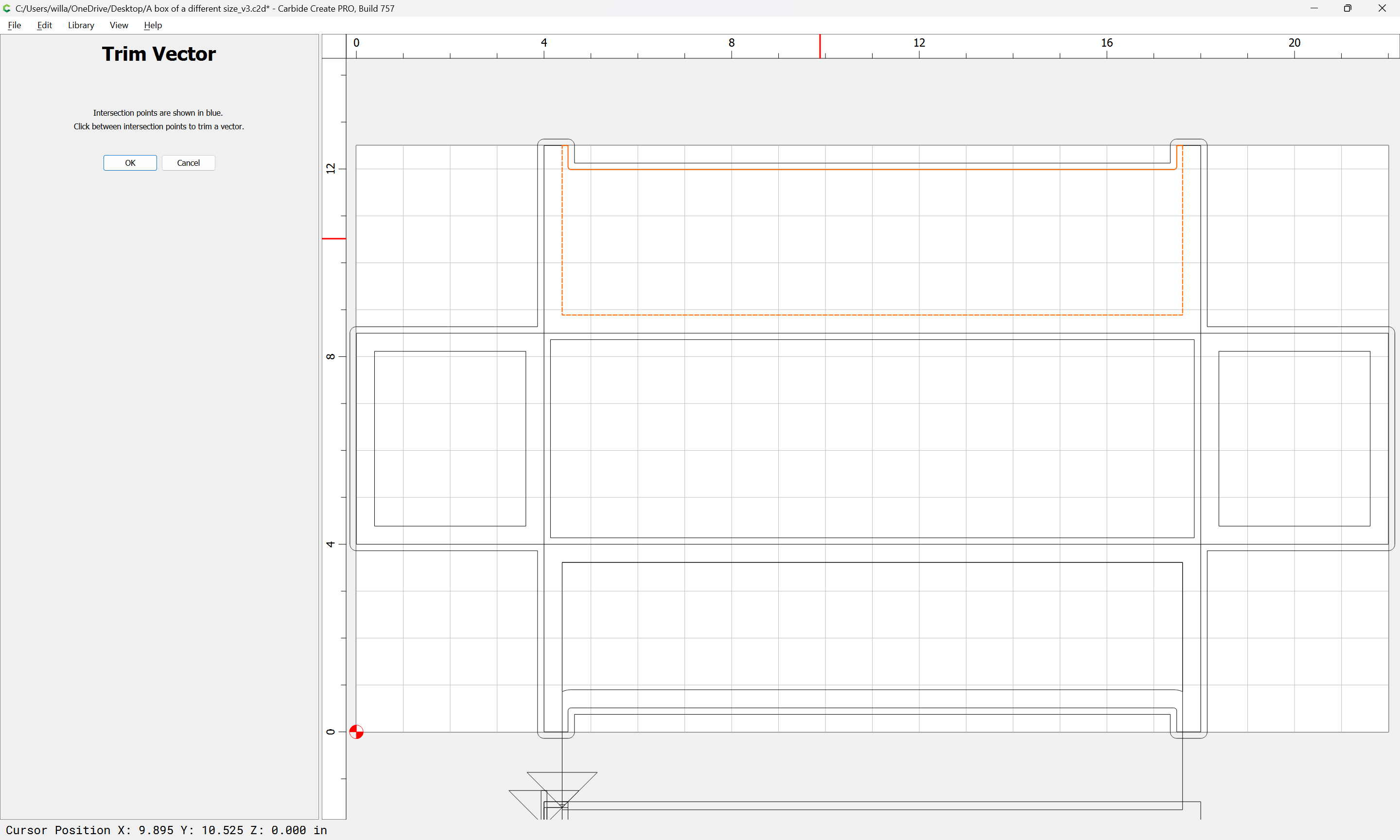
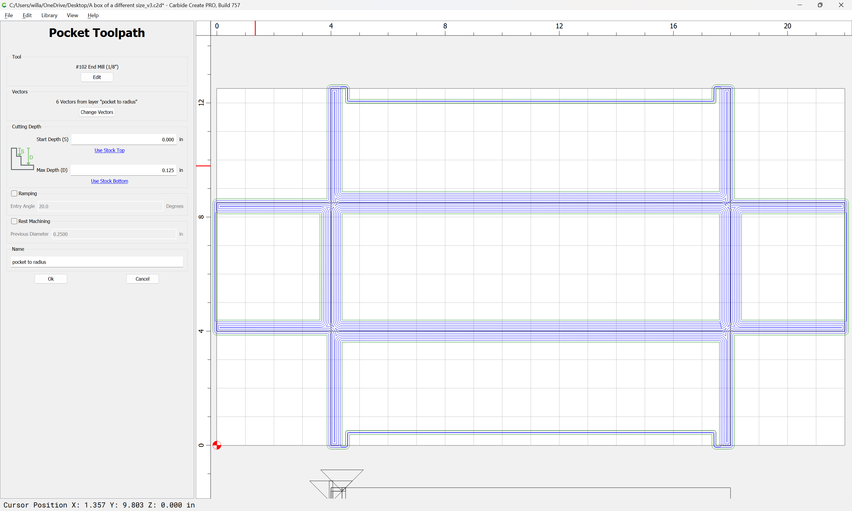
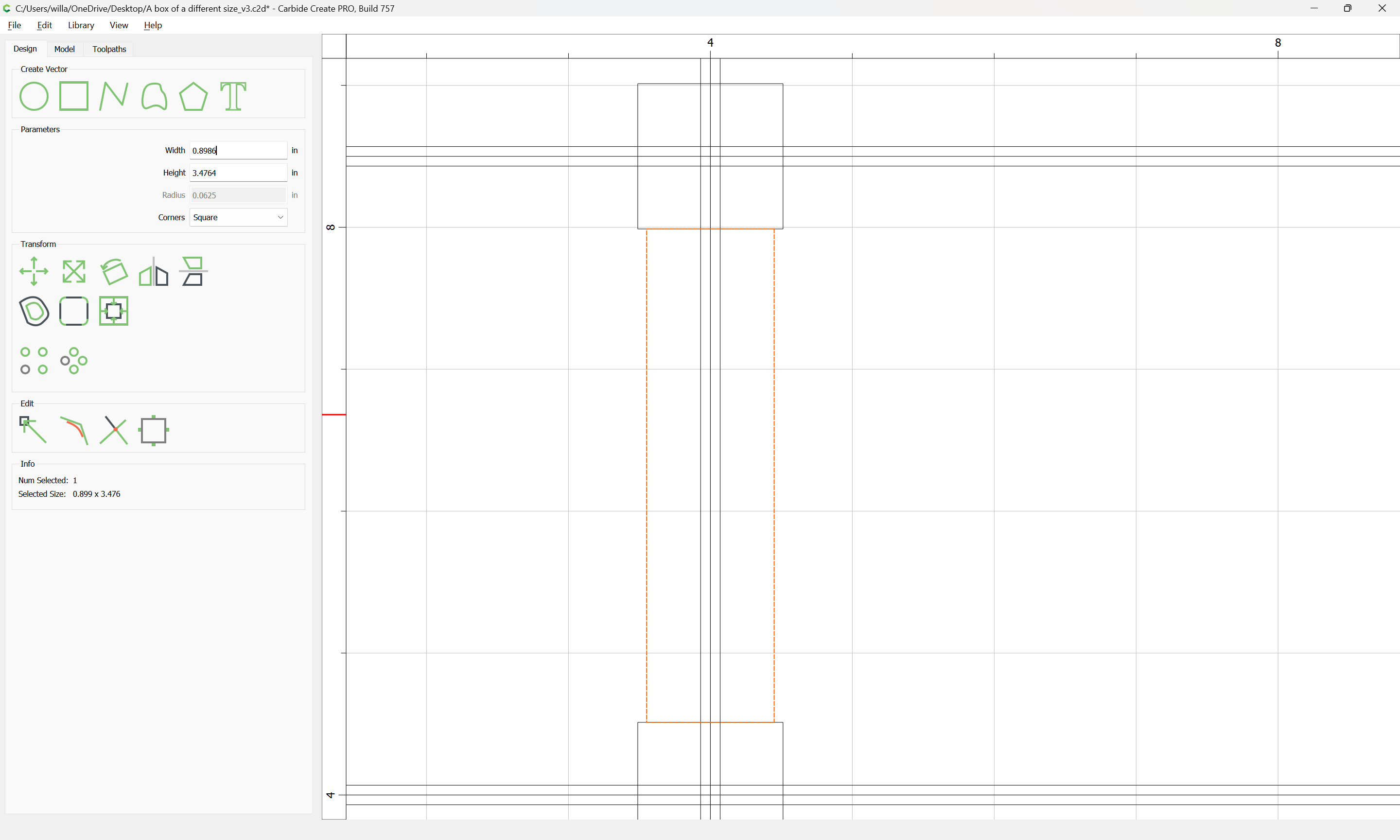
Since the joint needs to be inset by at least the tool radius, we can effect this by just reducing the width of this rectangle by the small tool diameter:

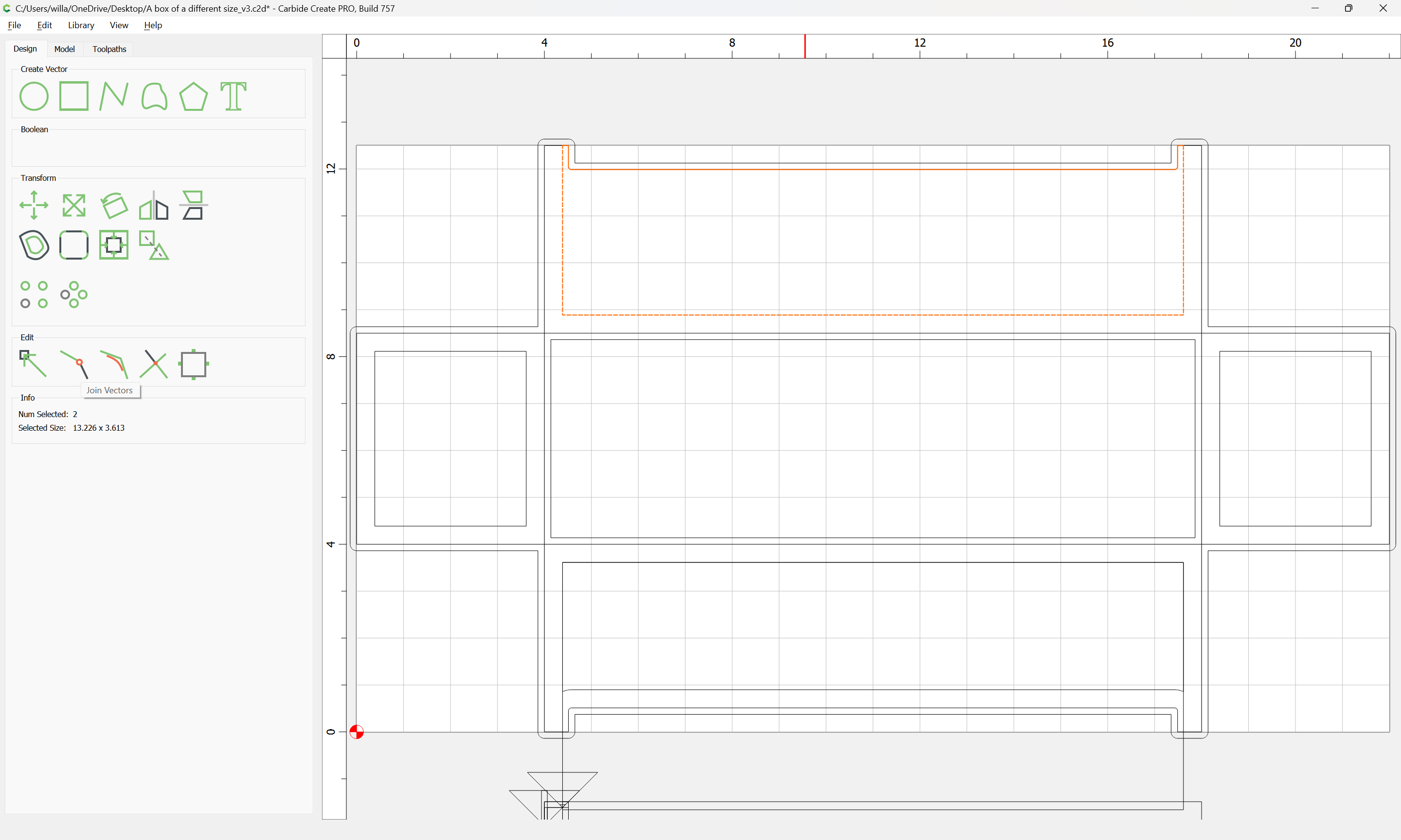
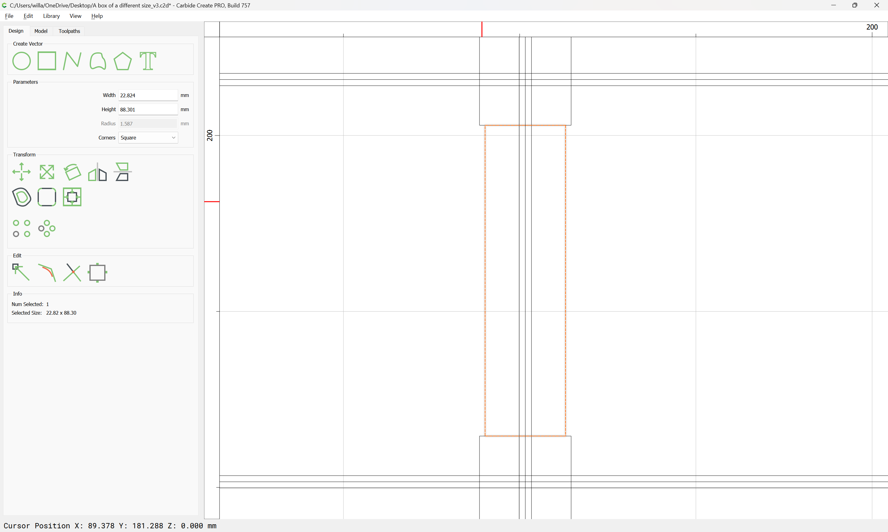
Switching to metric allows doing math w/o mixing units:

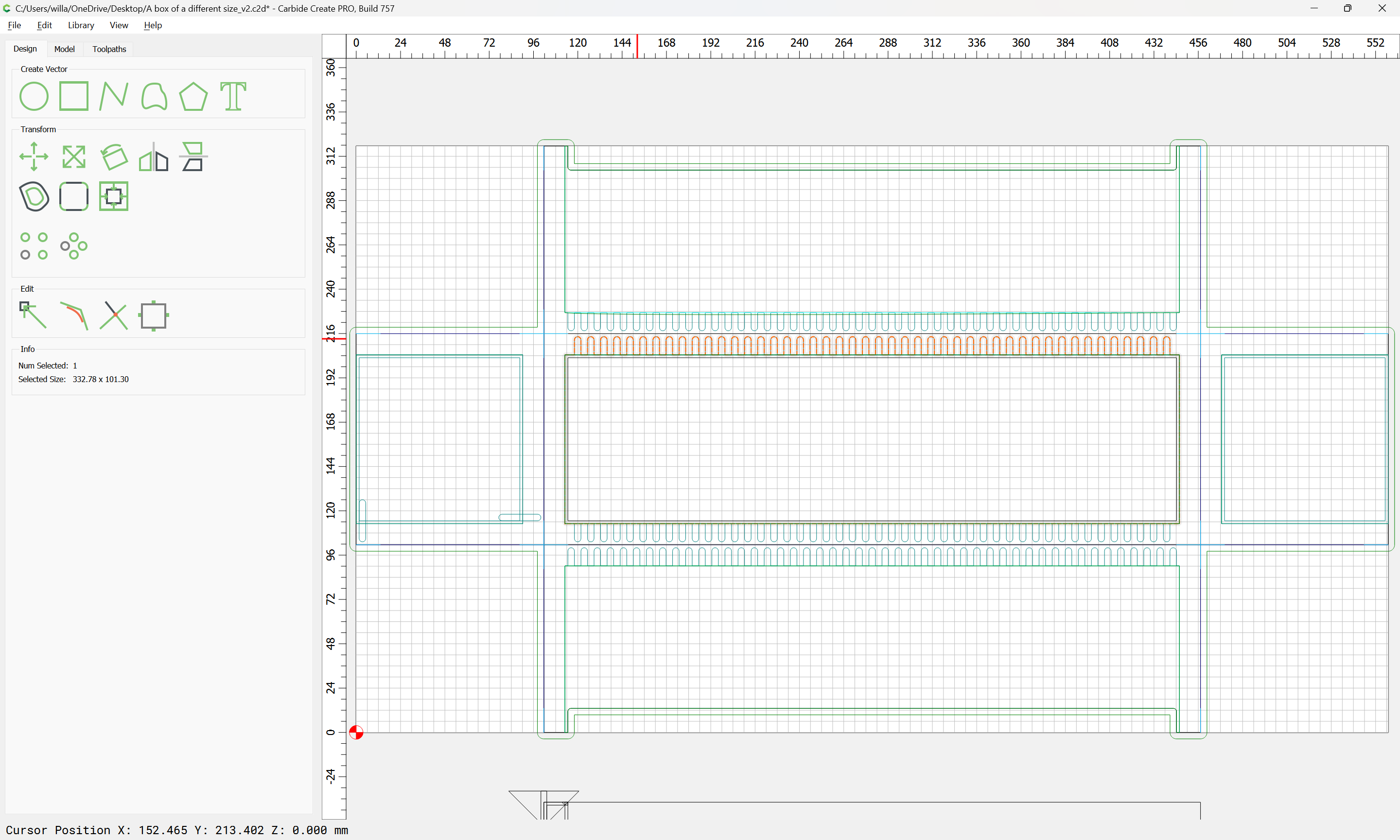
Essentially it is necessary to reduce each half to a series of projections and matching recesses — these must:

  • be large enough to reliably match the ability of the program to fit a tool into it
  • be easily created and shifted about — a consistent/centered placement helps with that

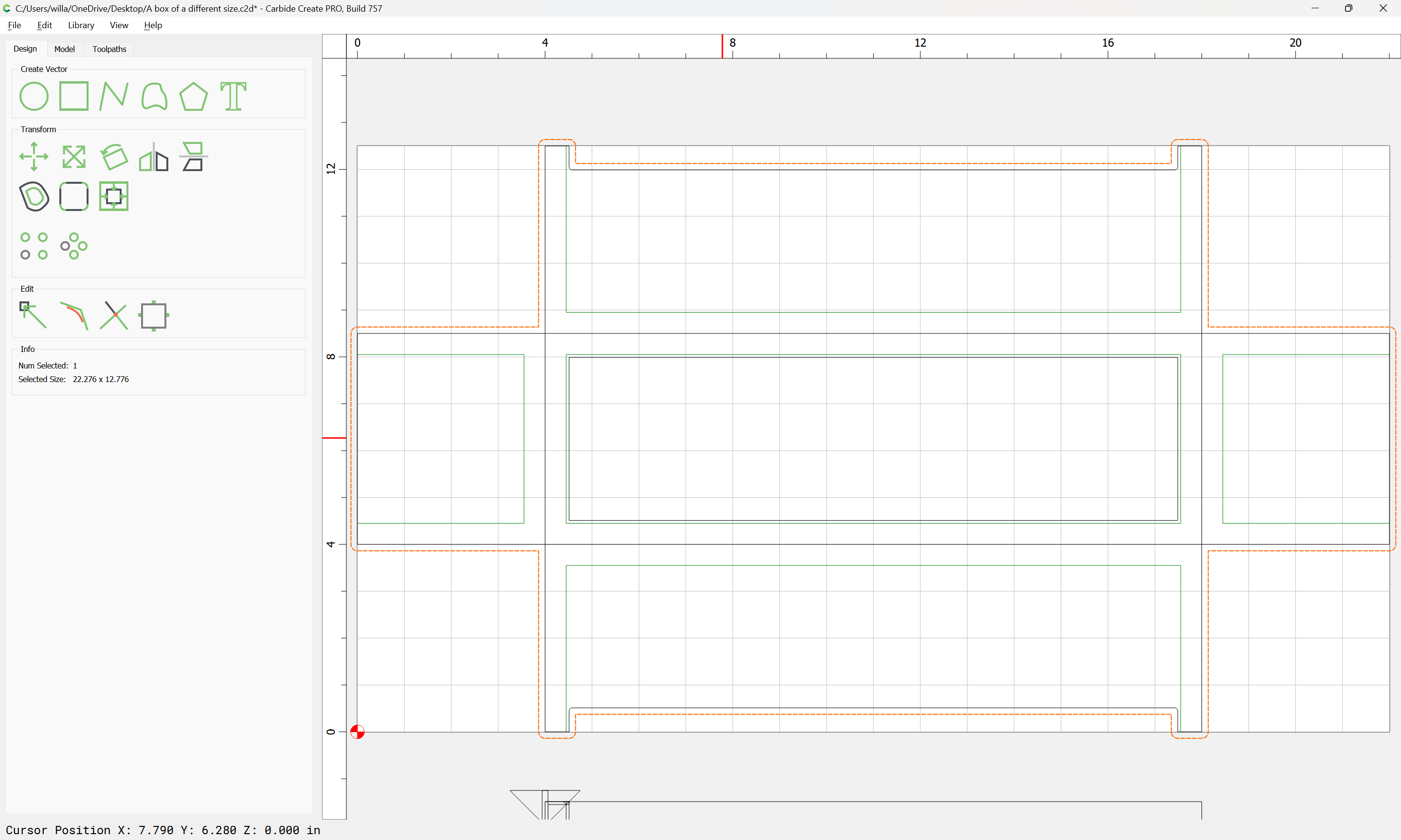
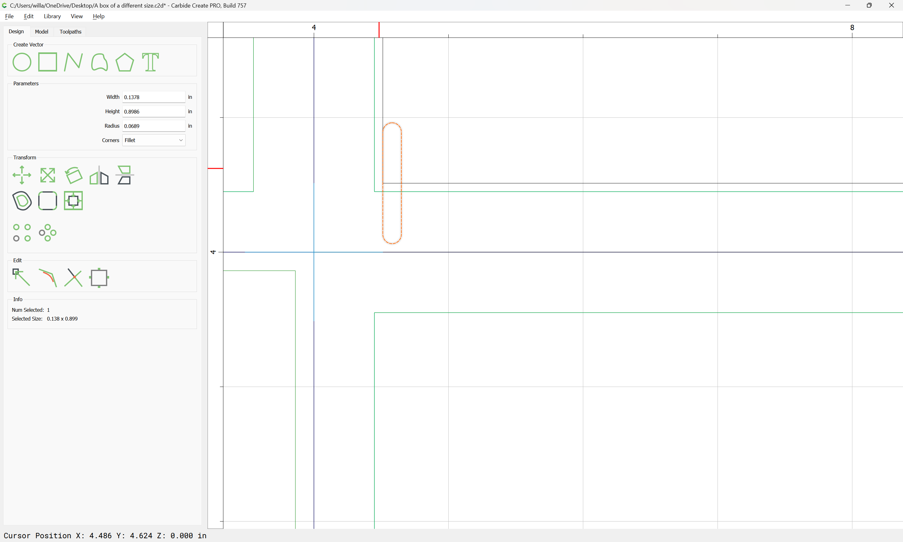
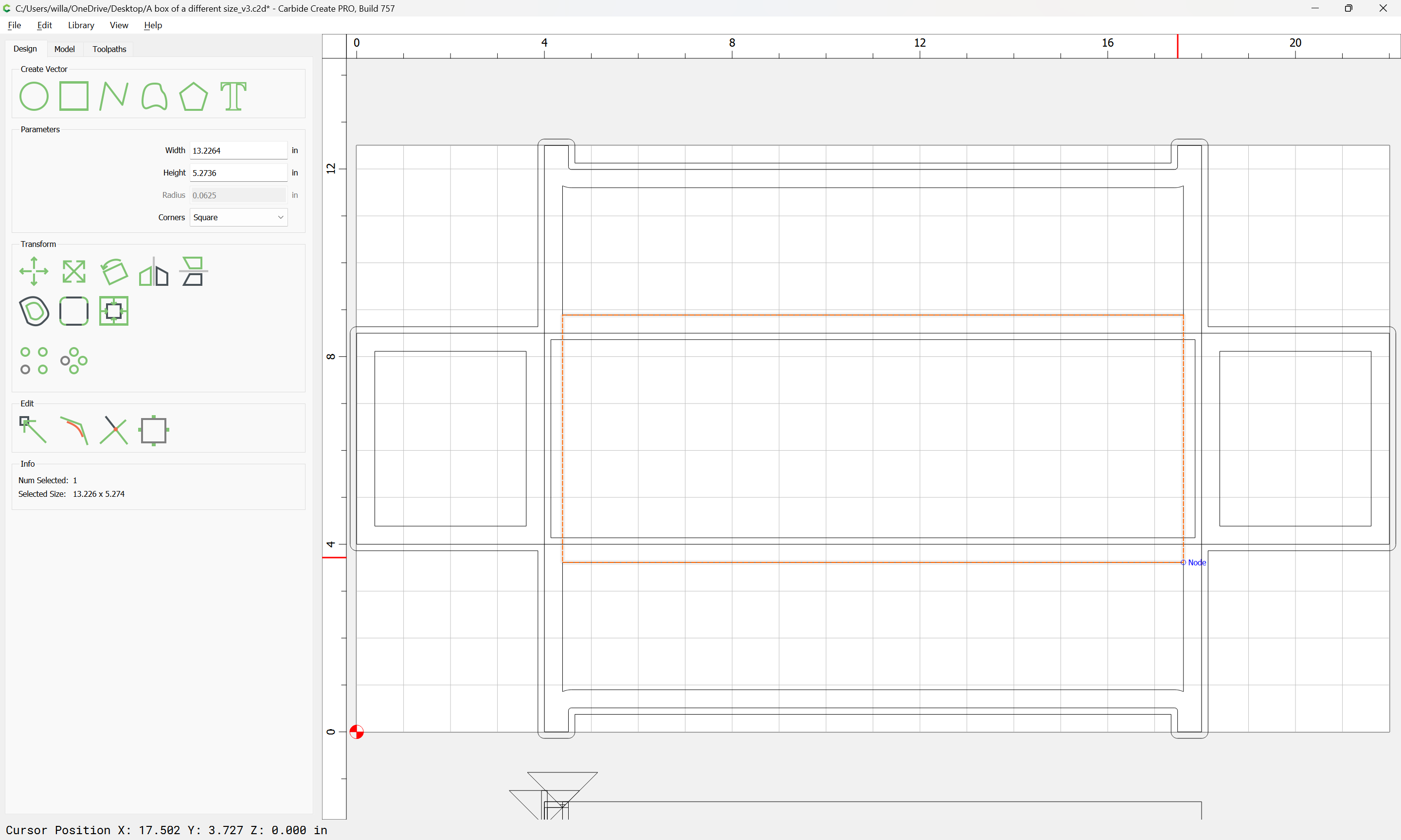
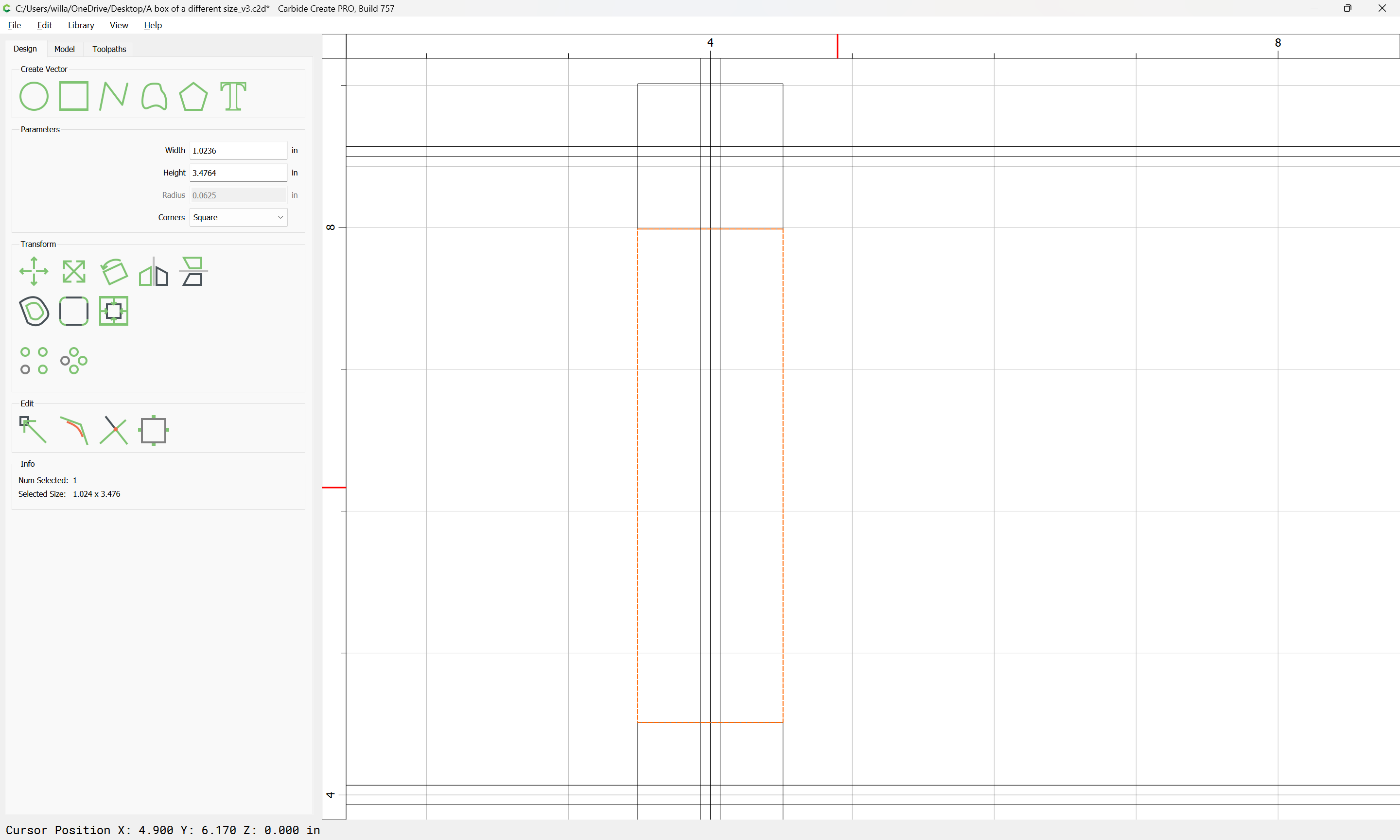
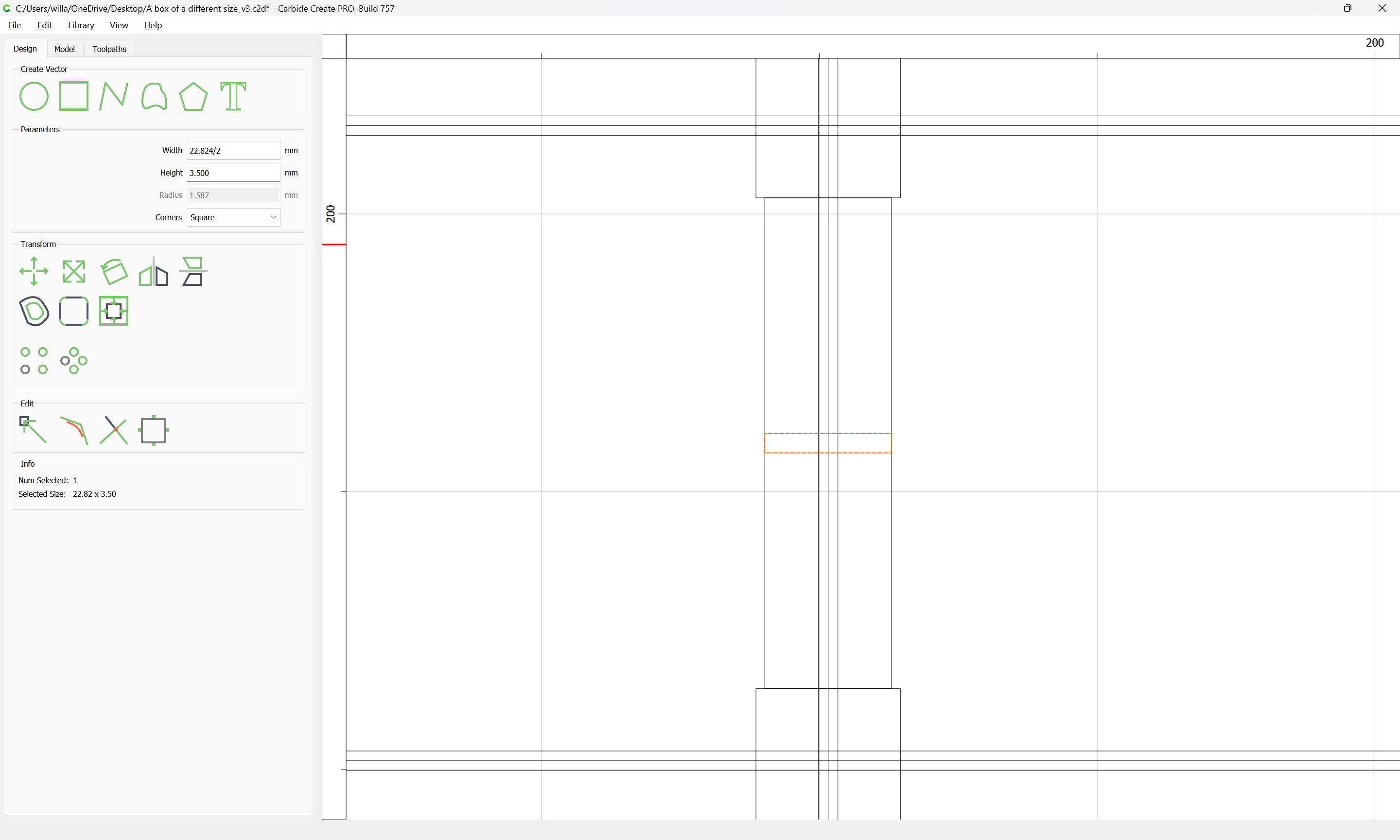
One can either cut these features at a consistent width, or scale them — probably a consistent width is easier to manage, and avoids the possibility of the tool not fitting, and if it covers a region greater than necessary is easily centered:

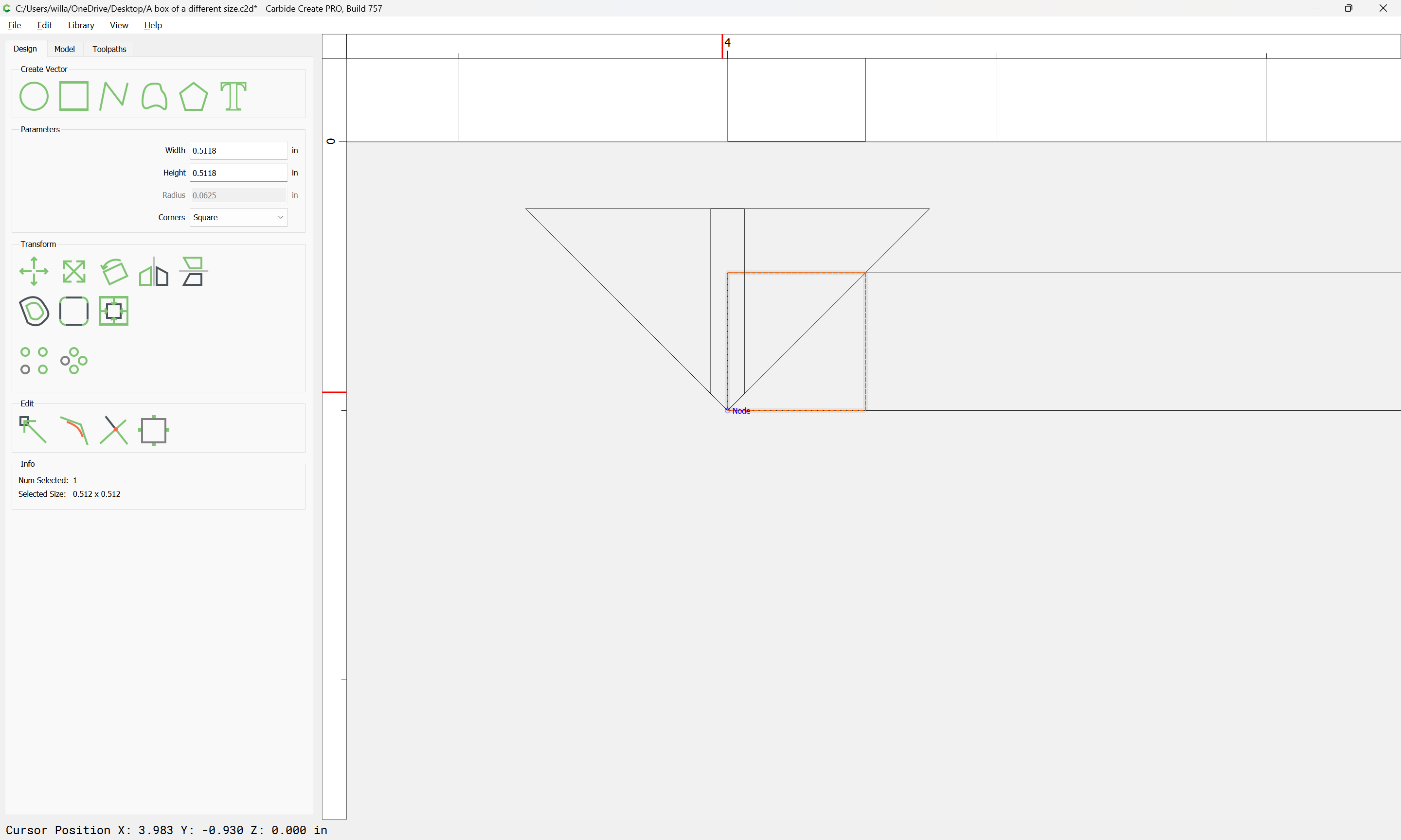
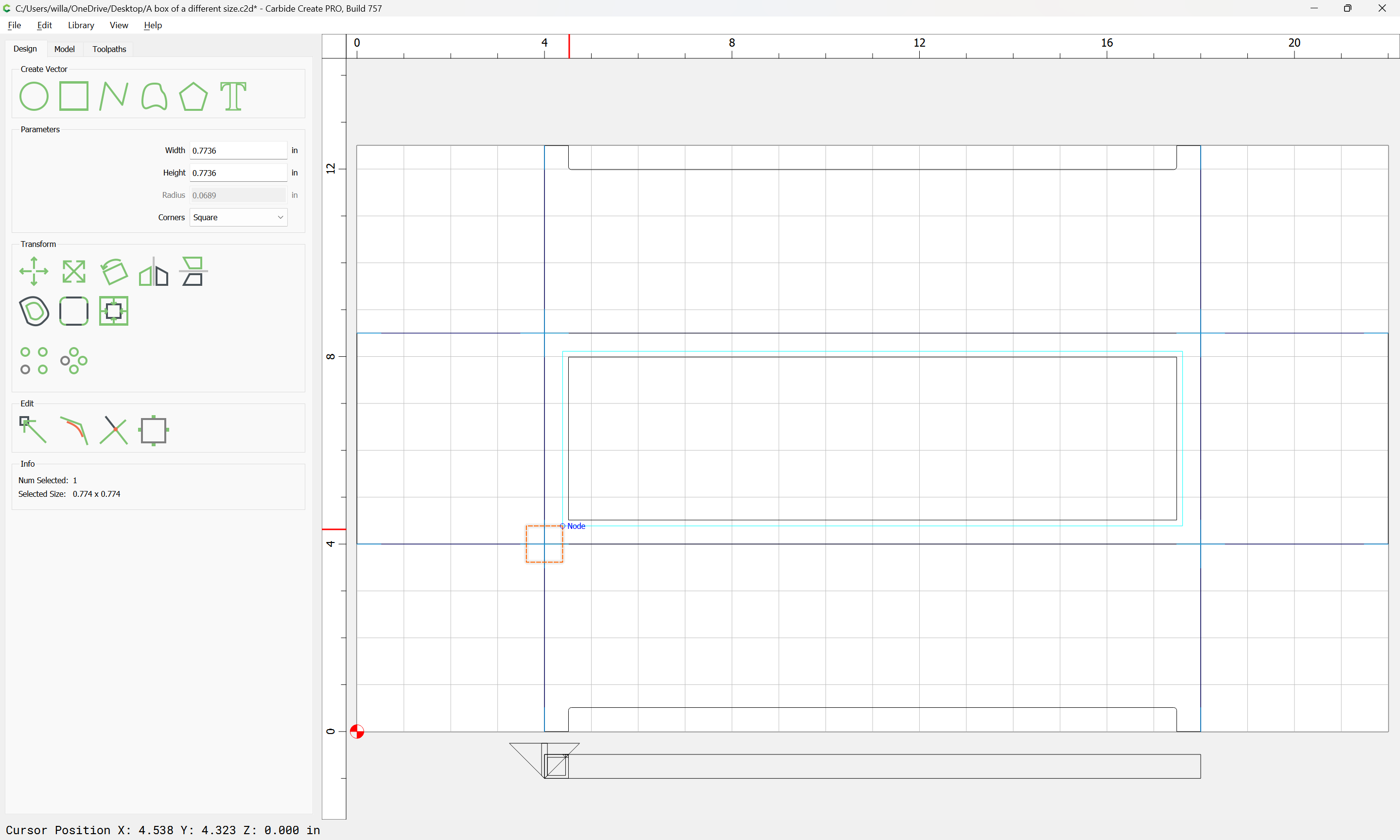
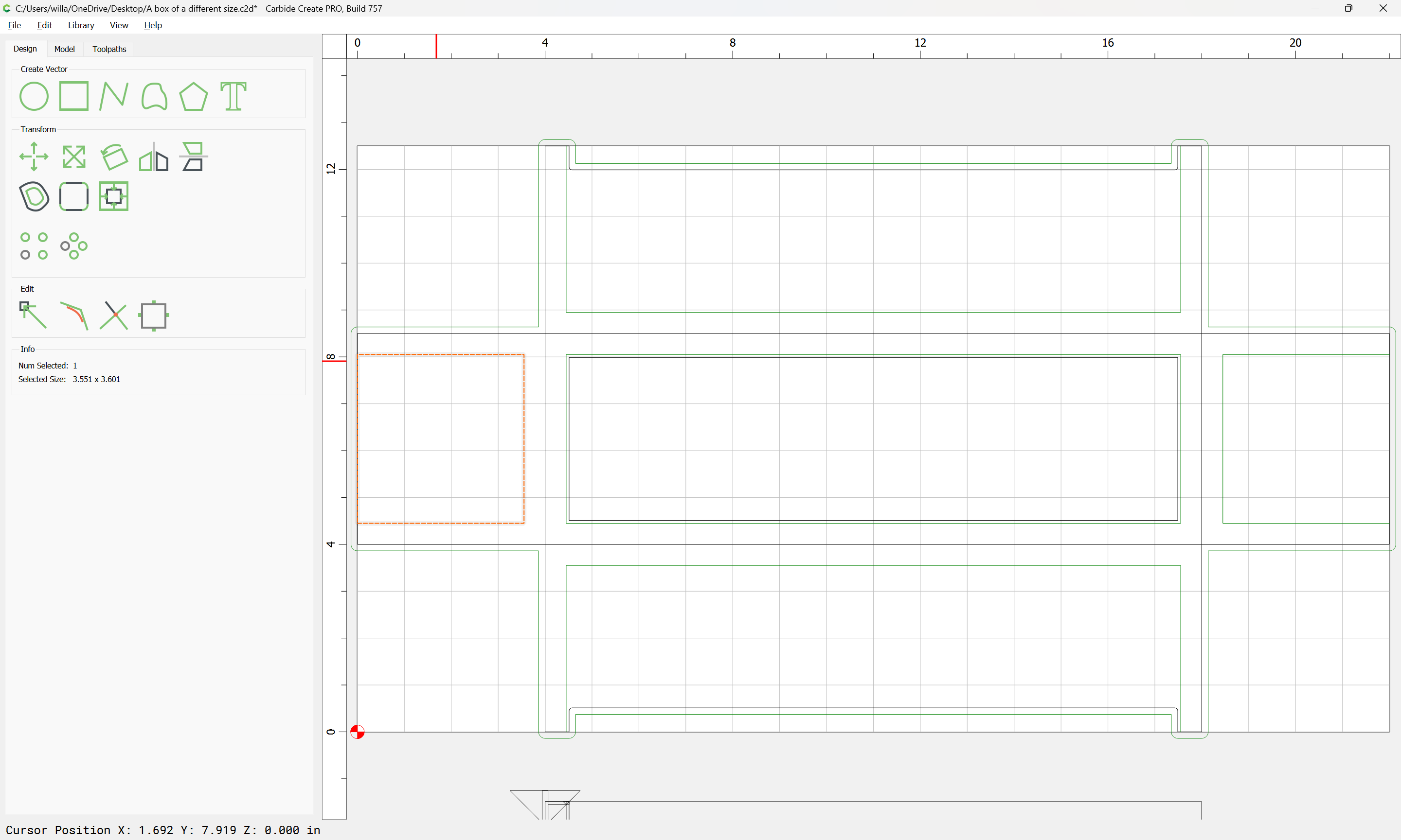
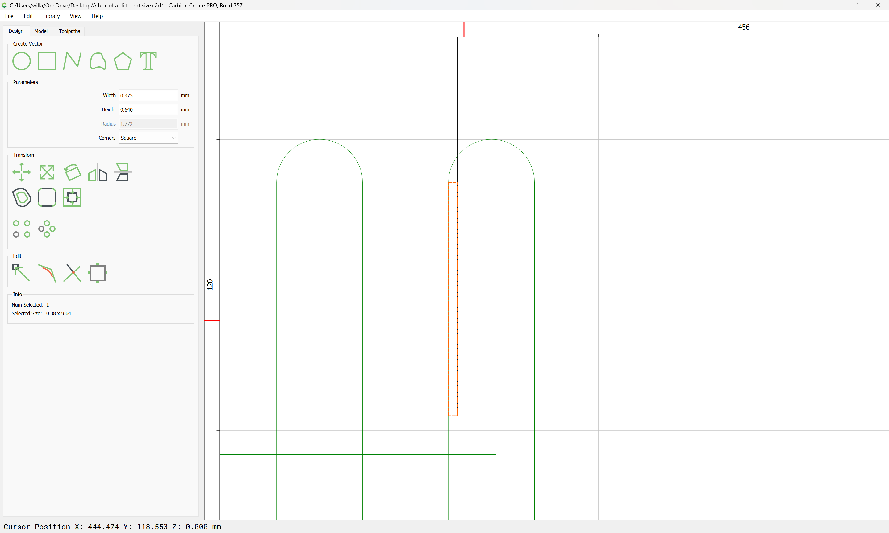
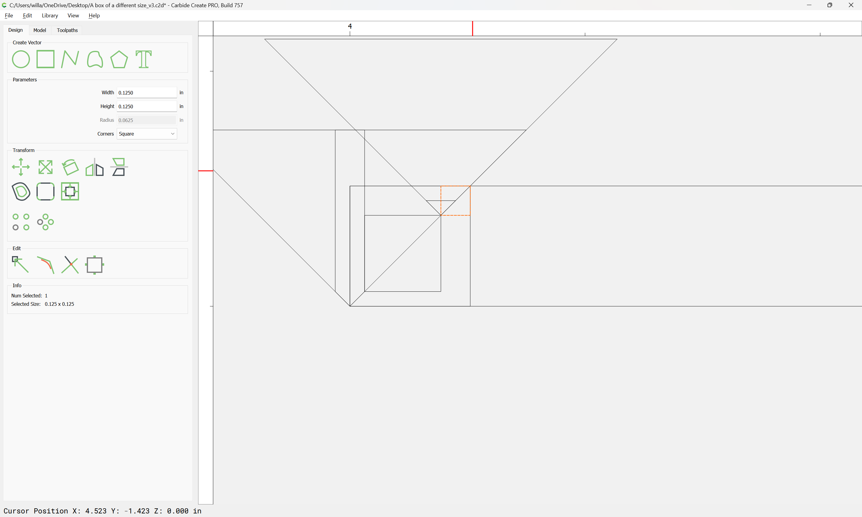
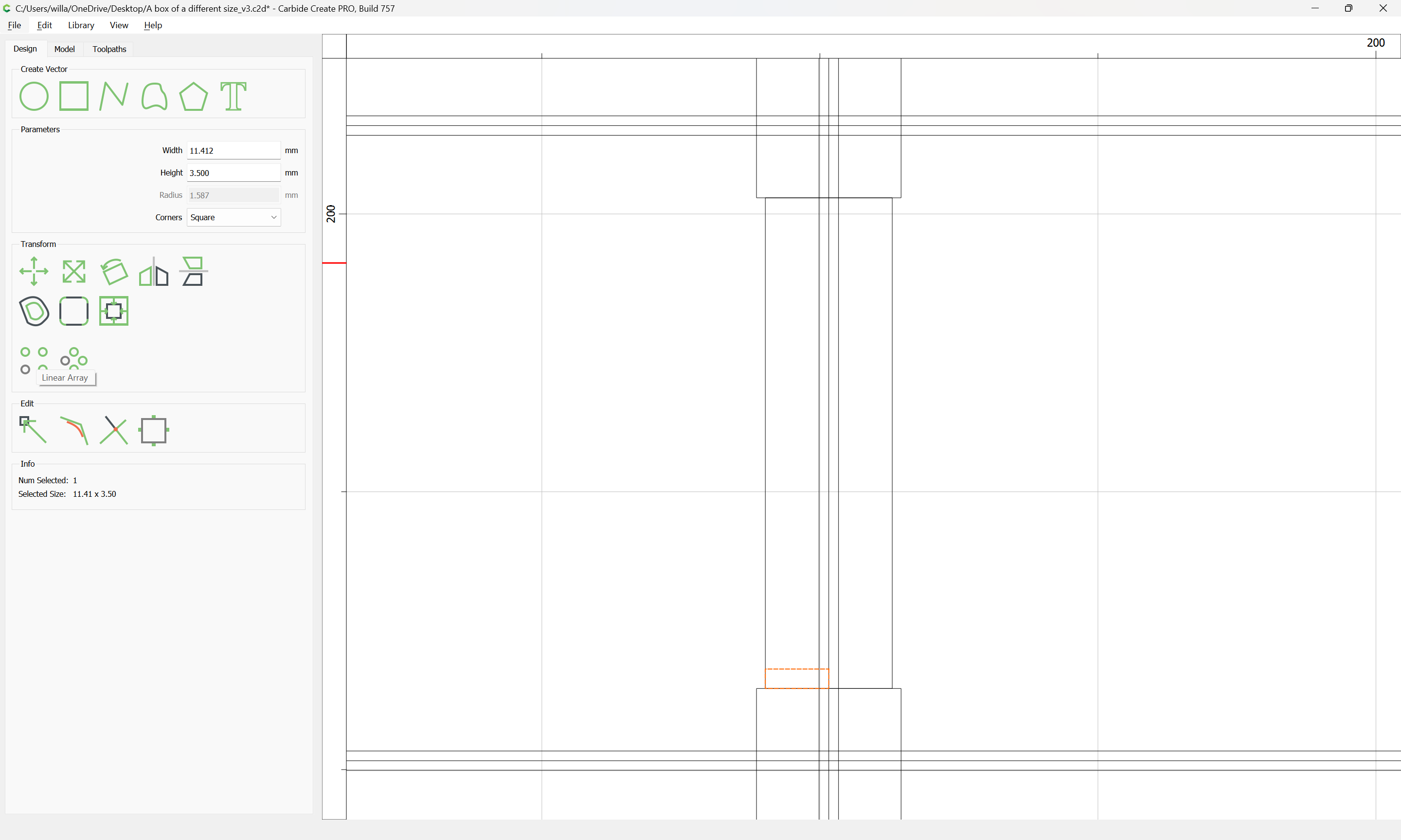
copy-paste the rectangle, then change the dimension along the axis of the joint to be the desired width:

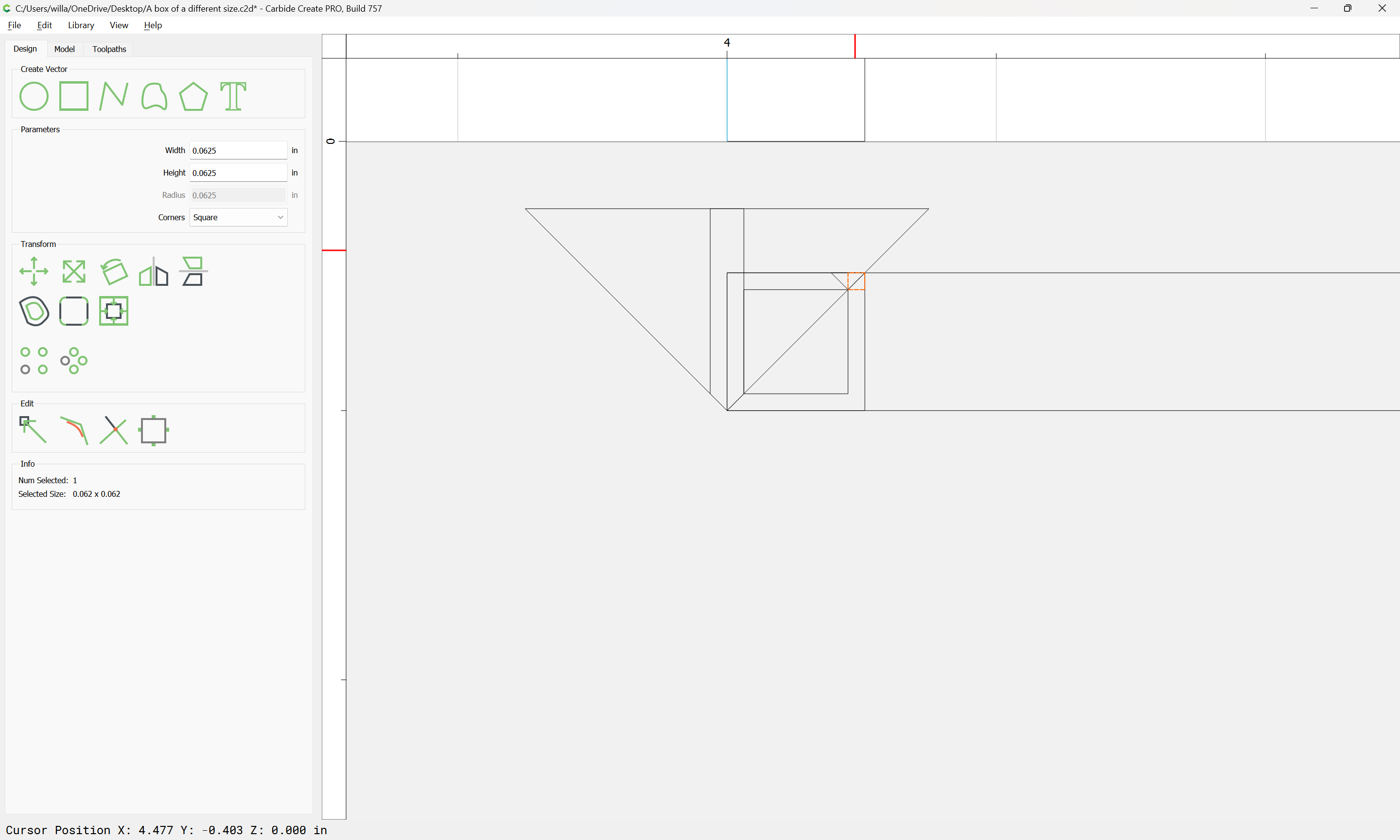
then halve the dimension along the other axis:

and drag it down to the lower left corner:

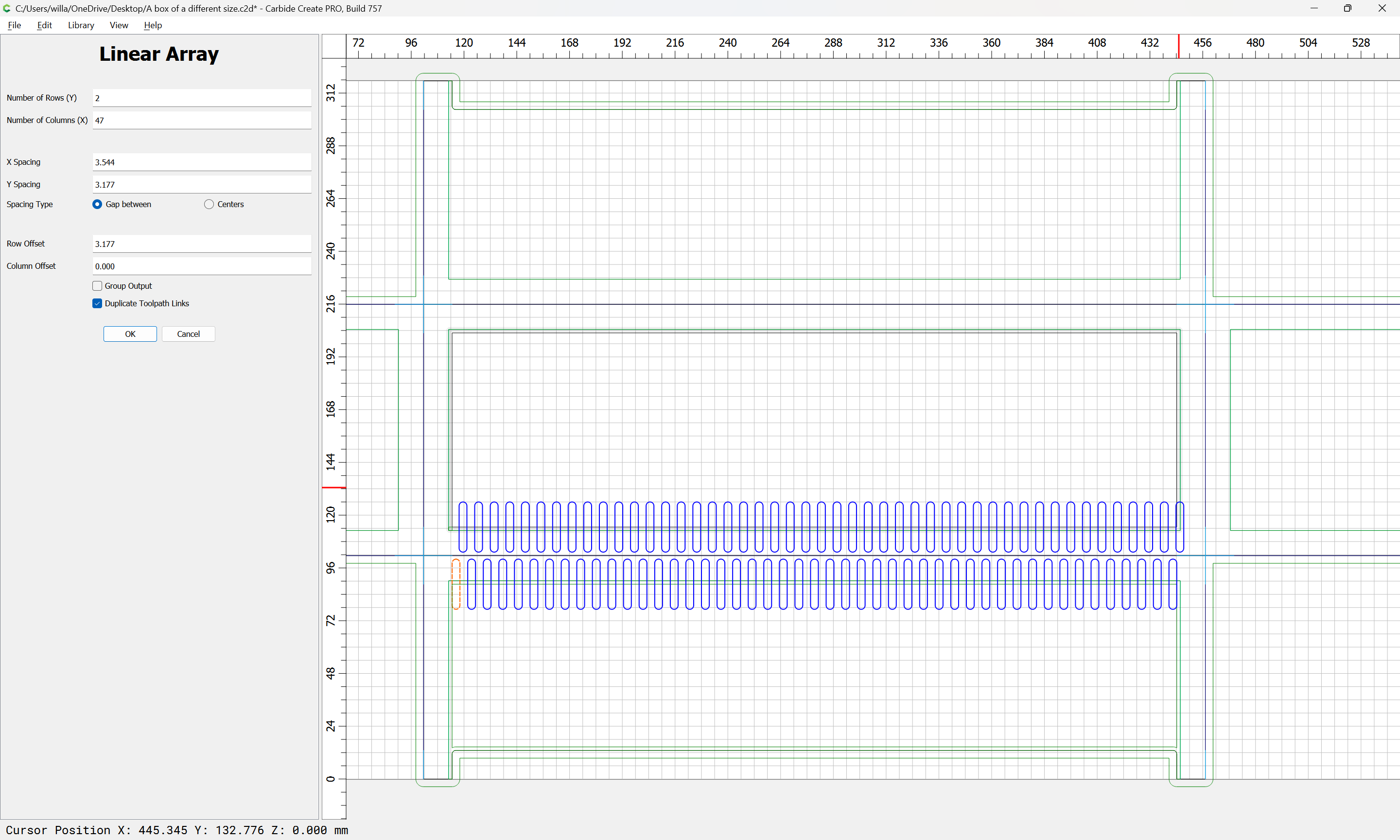
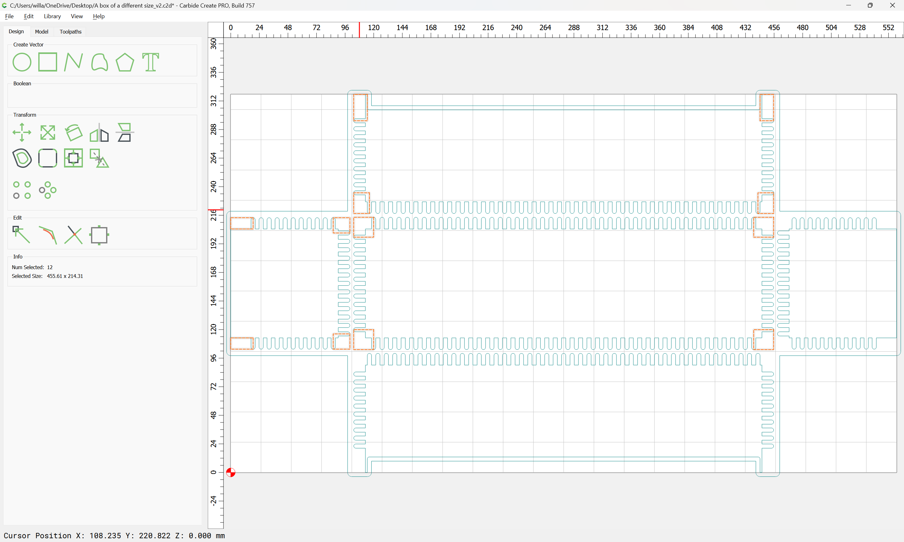
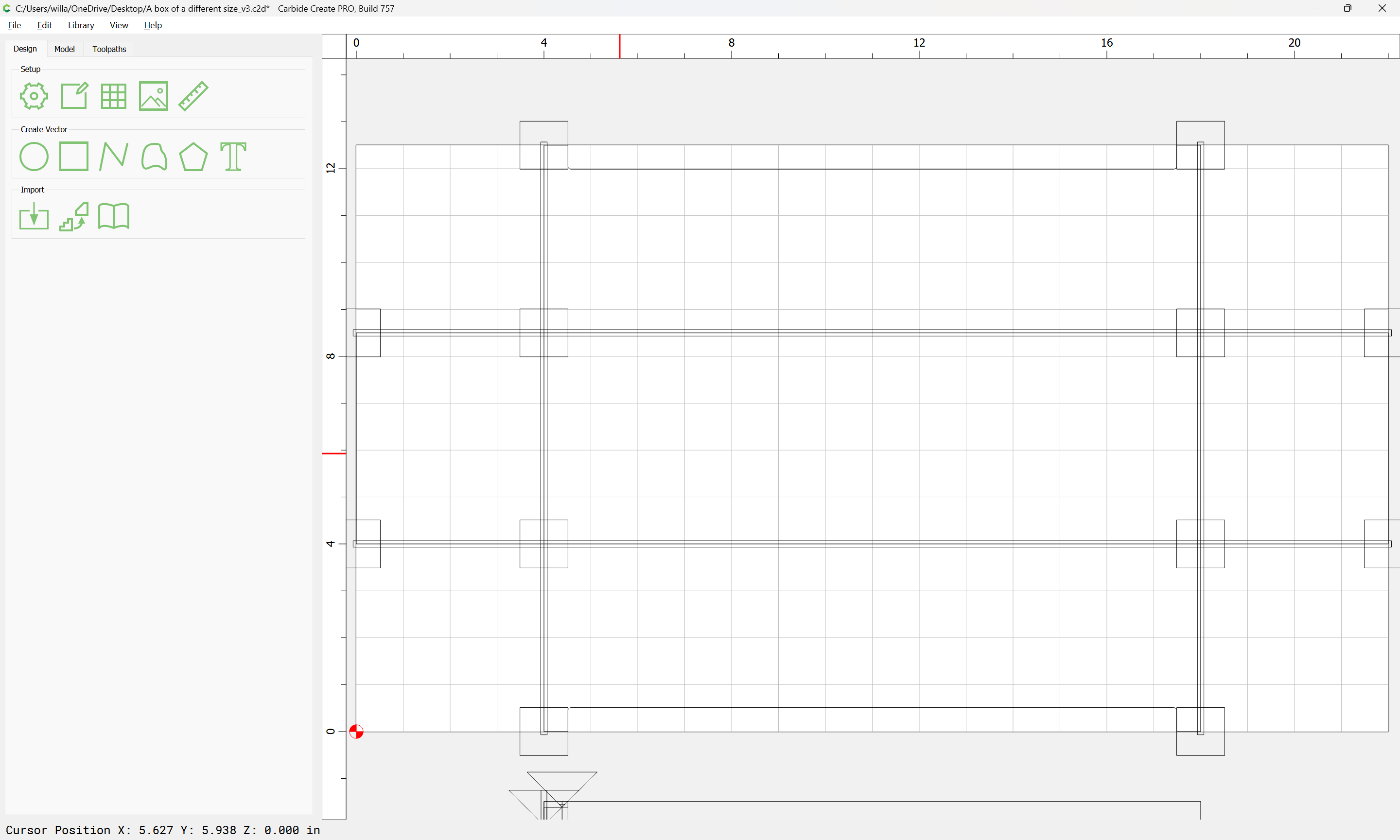
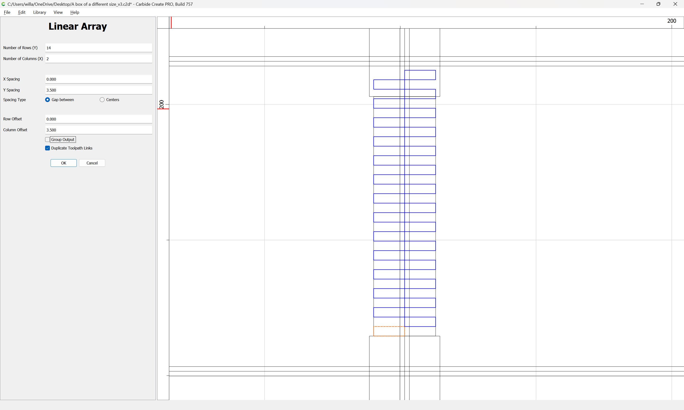
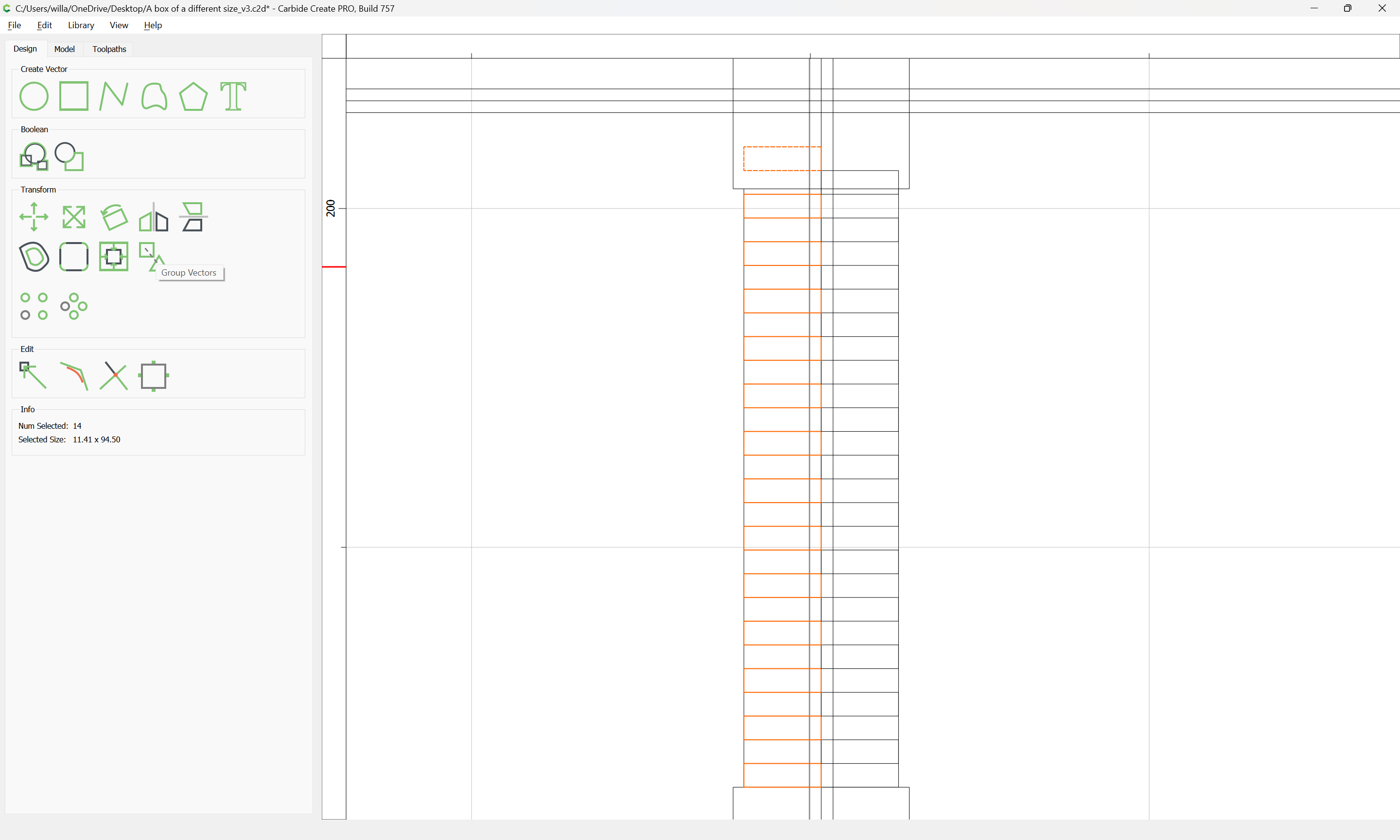
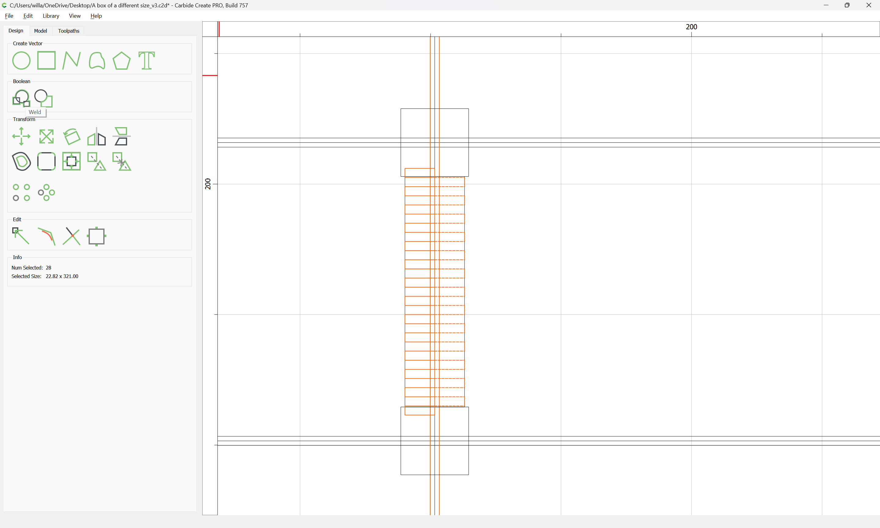
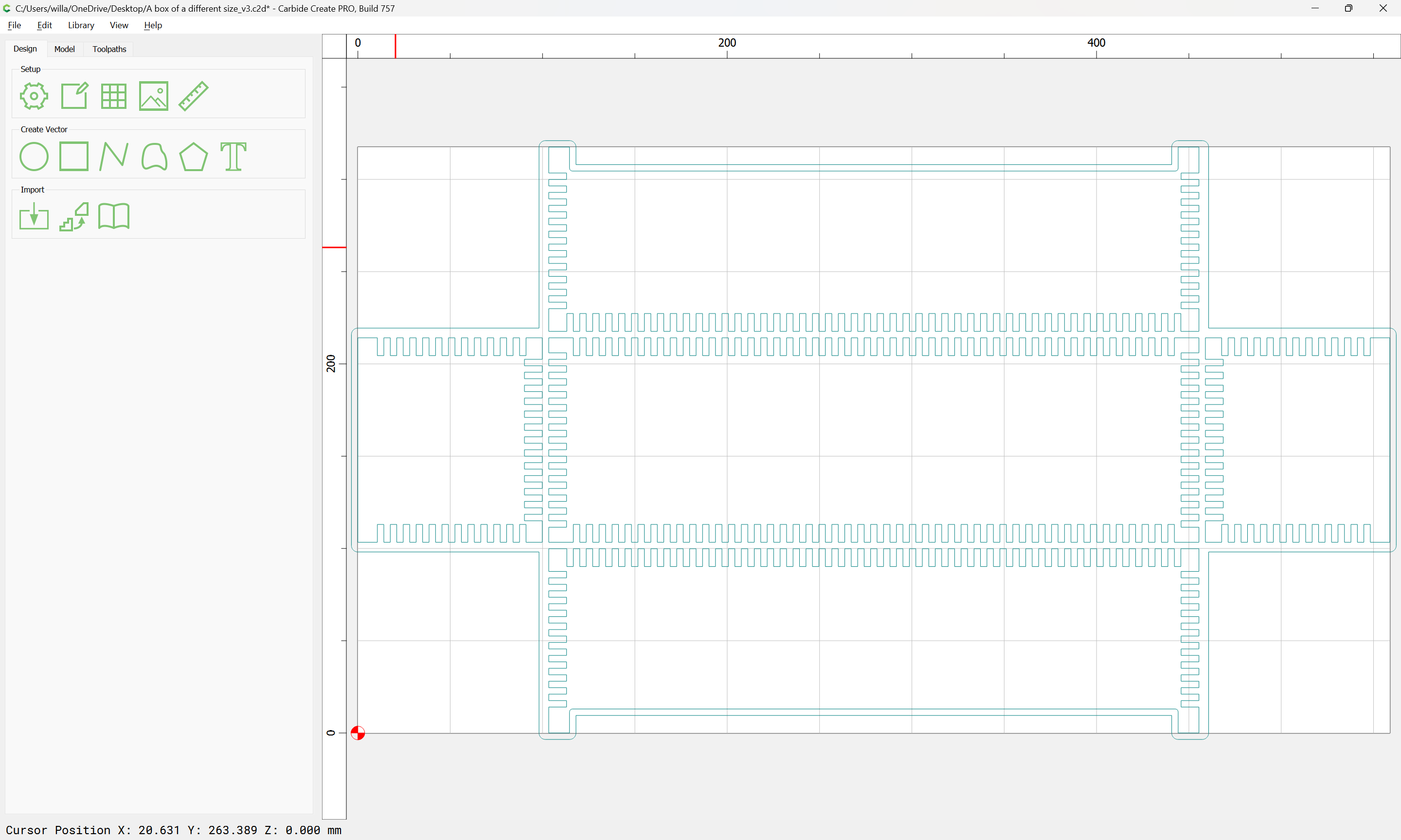
and set up a Linear Array which covers the entire region of the joint:

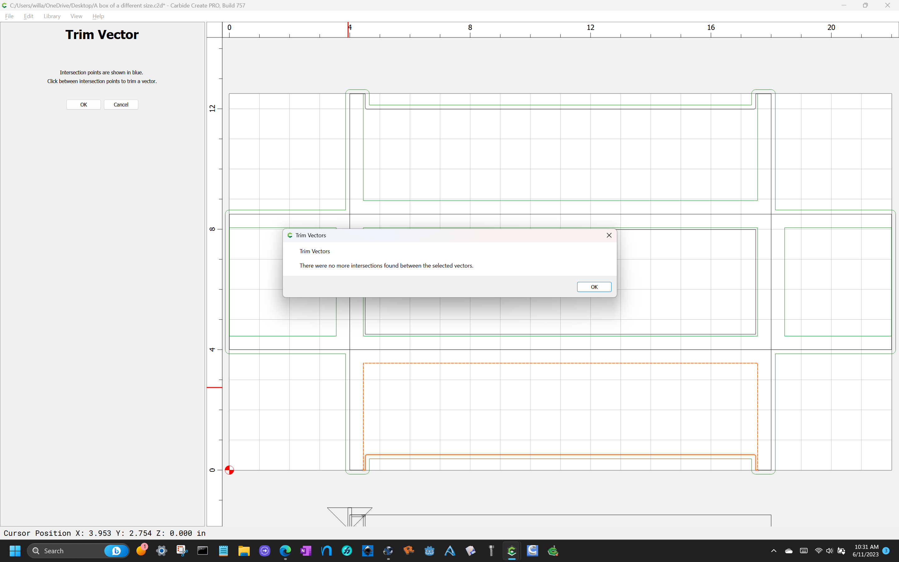
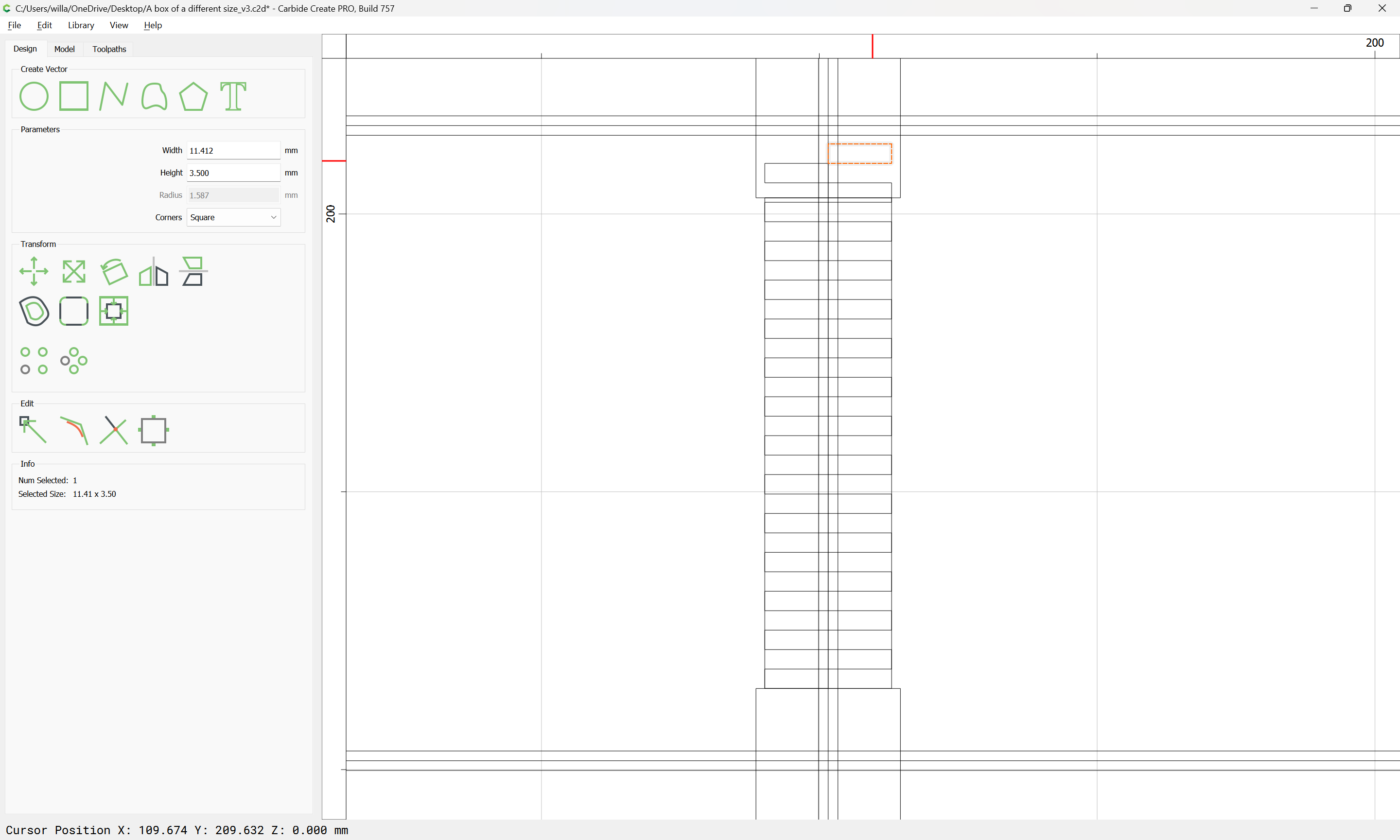
Note that we want one side to have an odd number, and the other to have an even, so it is not helpful to group the output — Delete the extra:

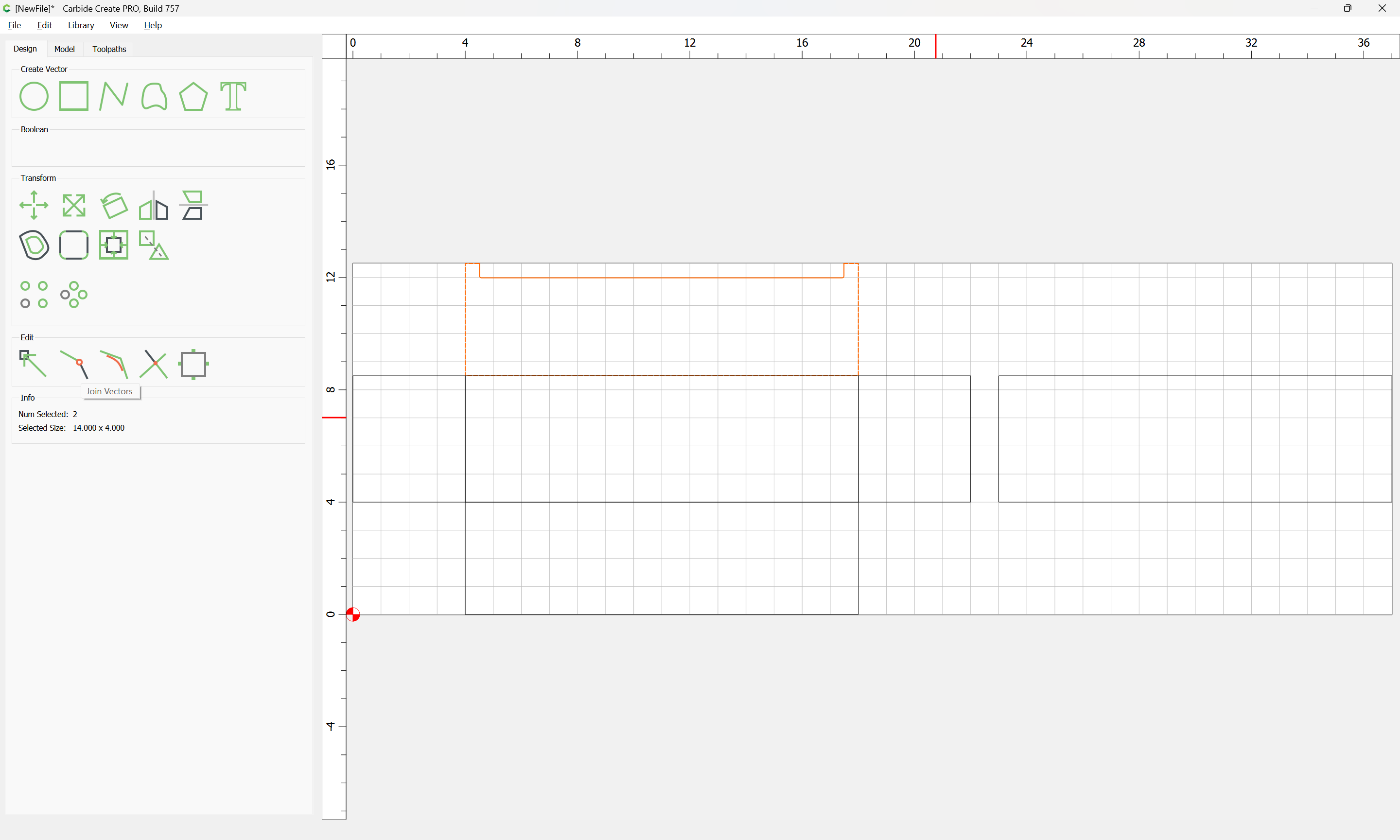
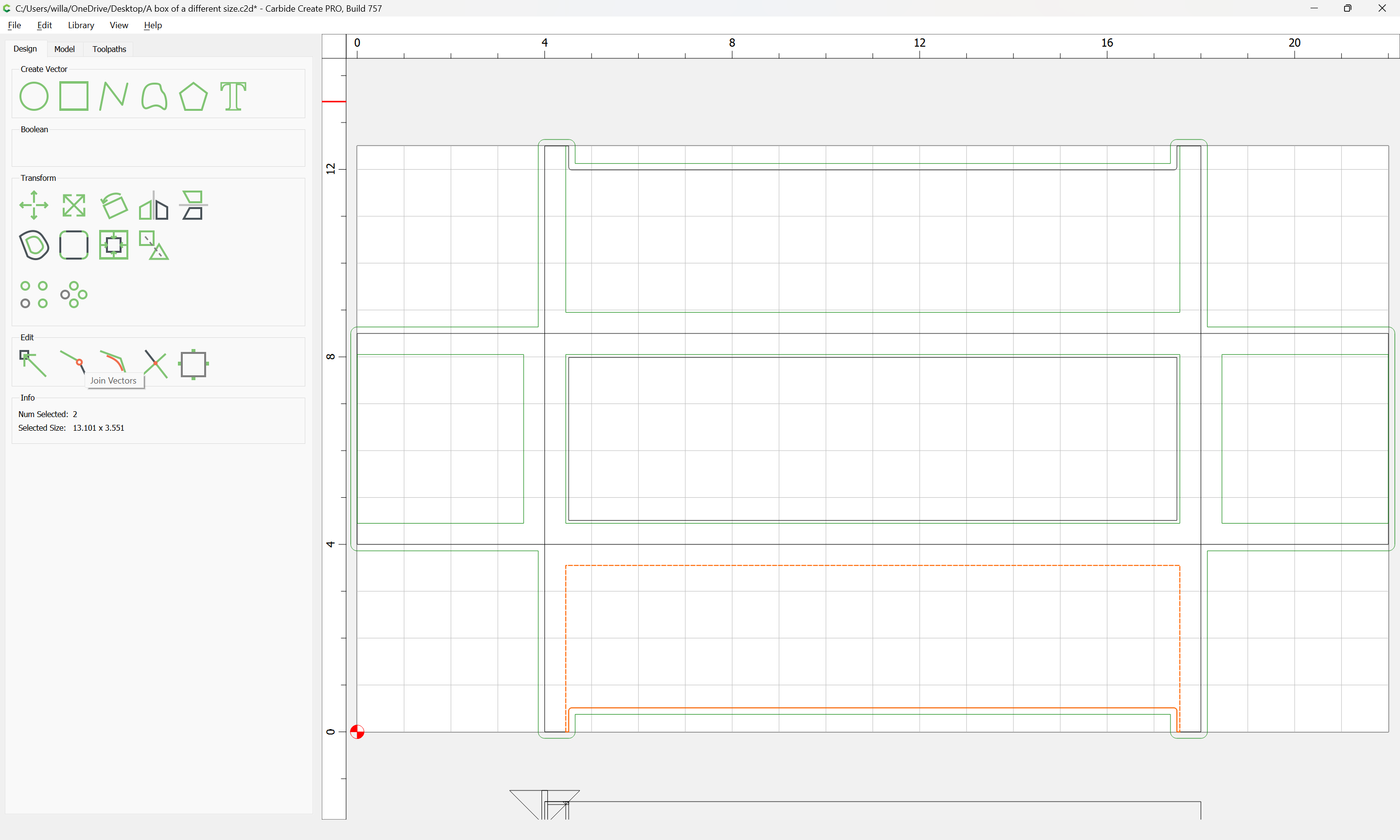
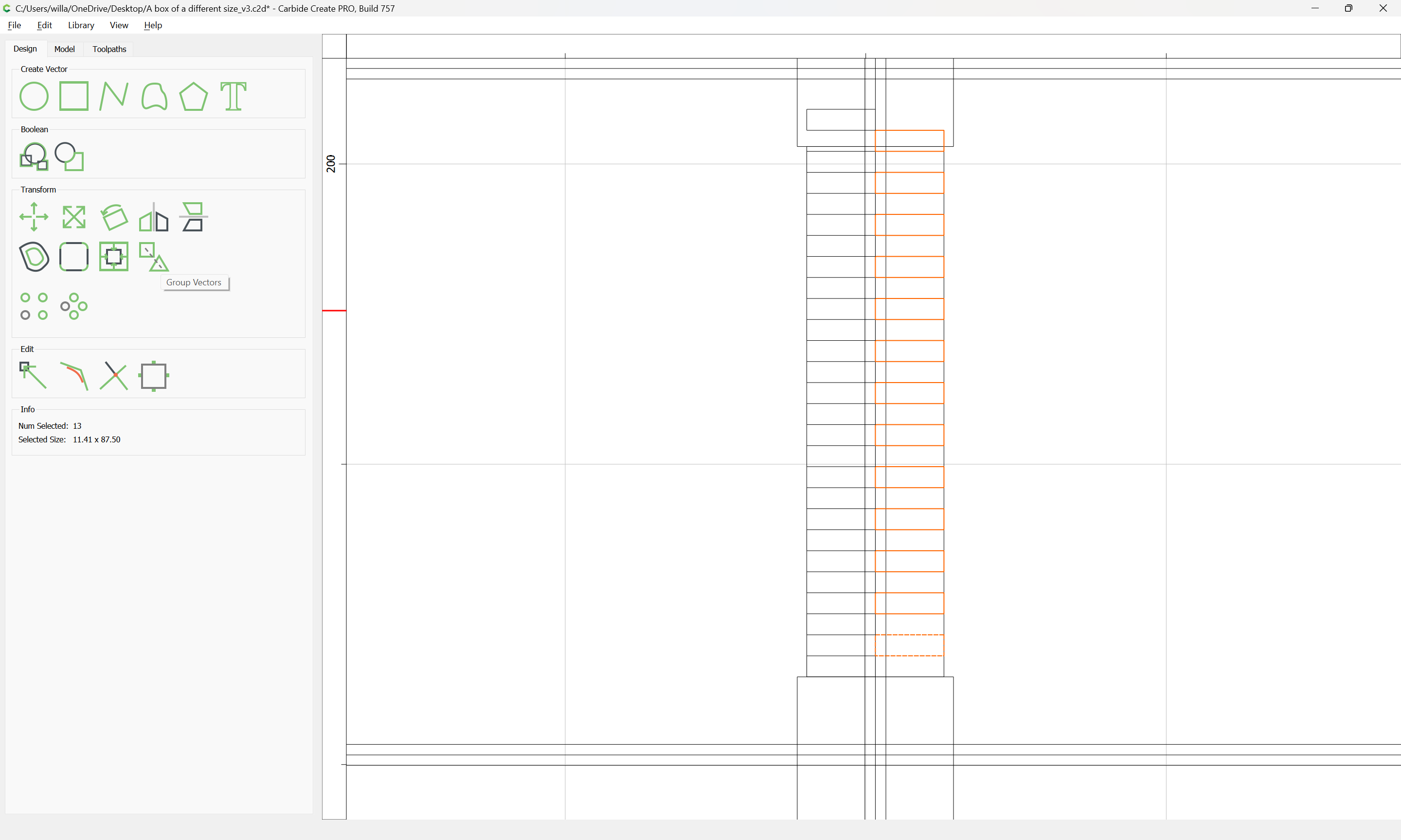
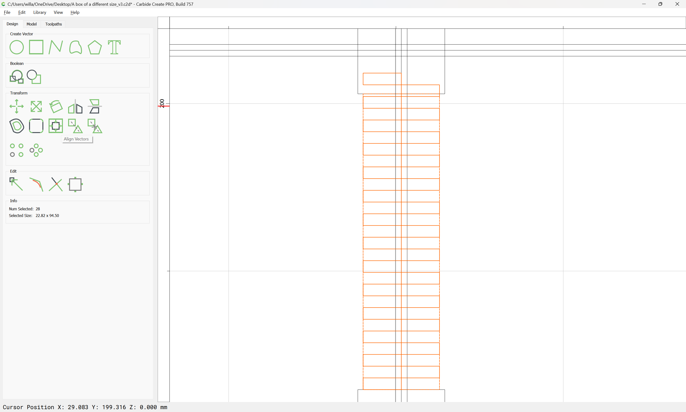
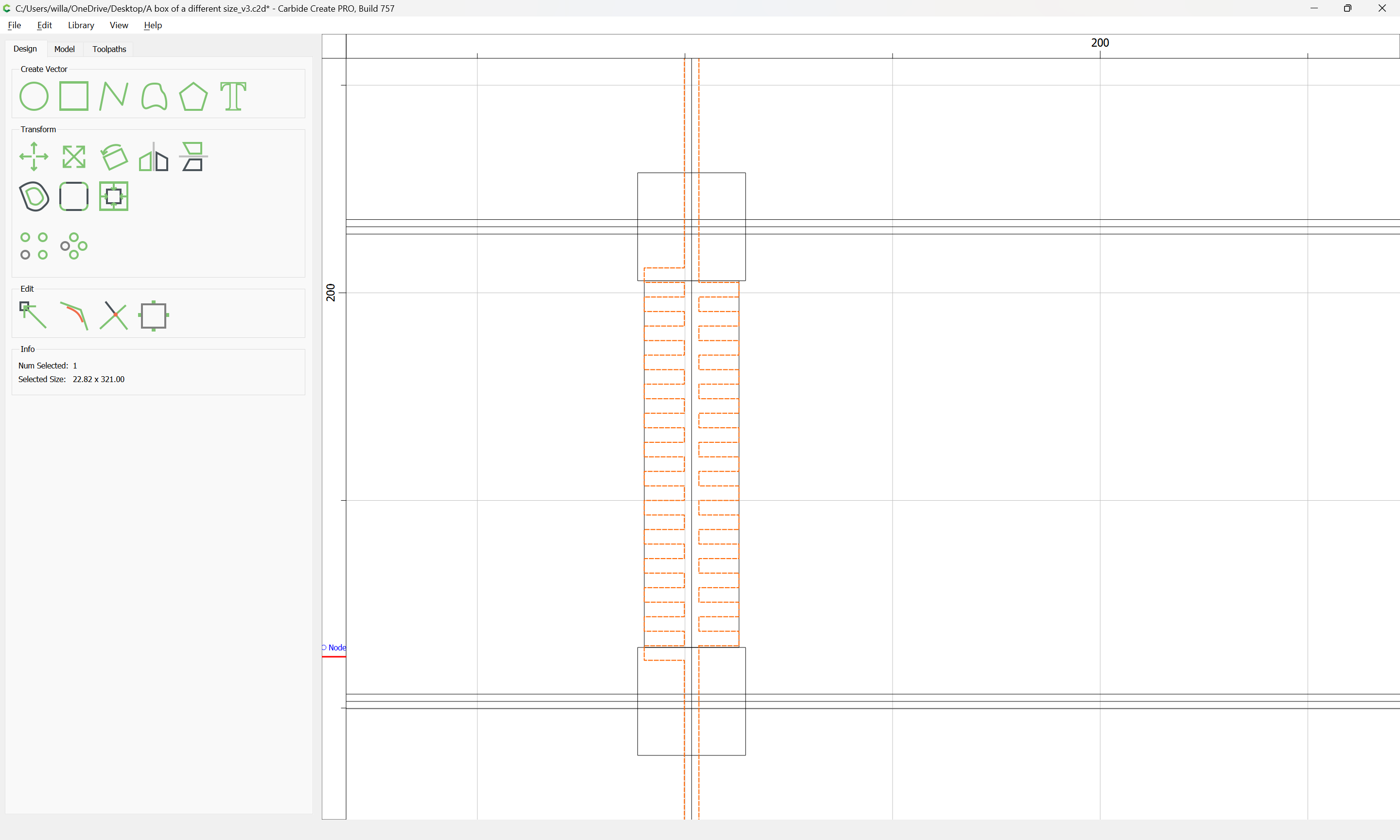
and select each side and group:

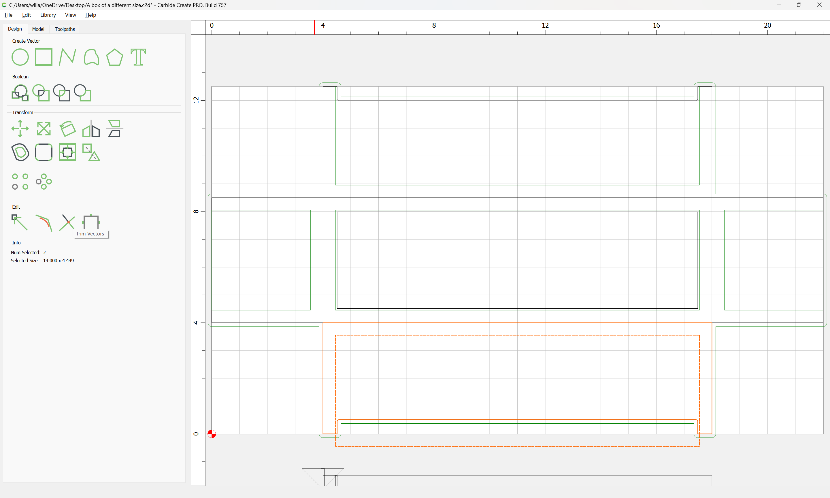
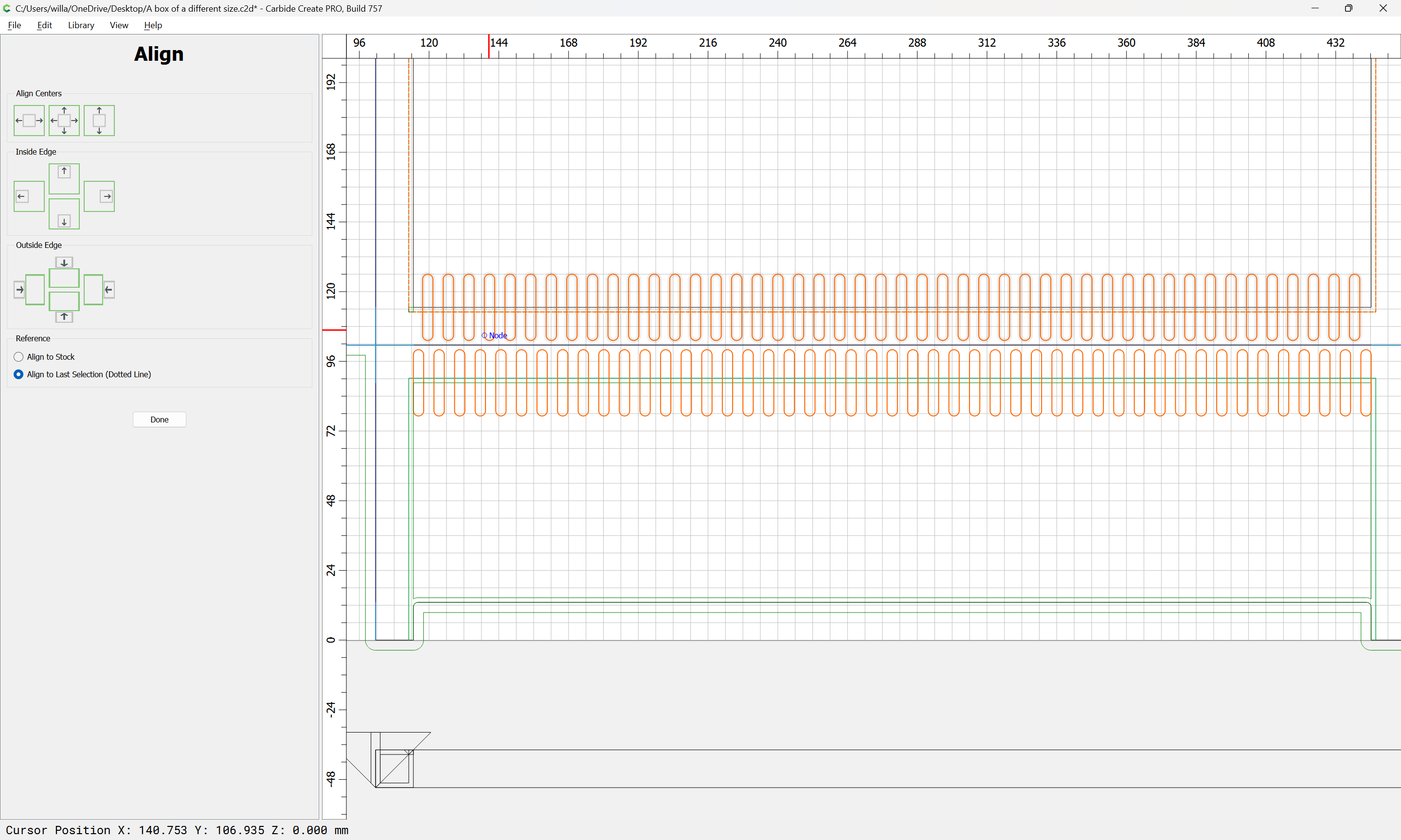
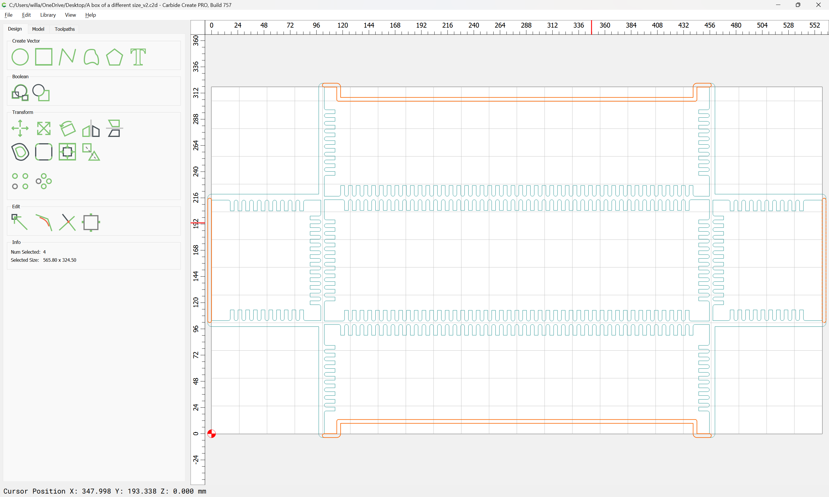
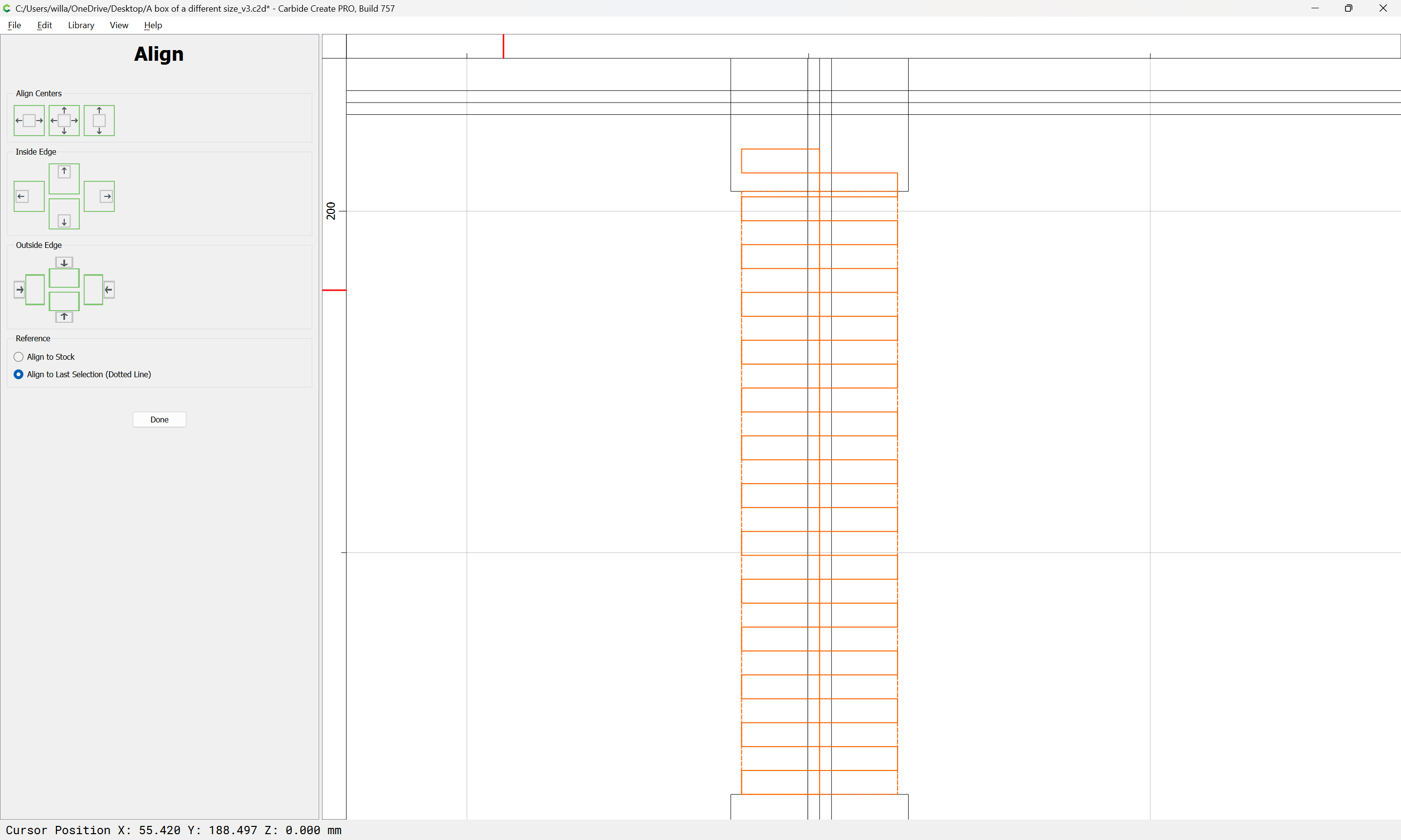
Select the two groups and the rectangle which defines the joinery region and use the align tool:
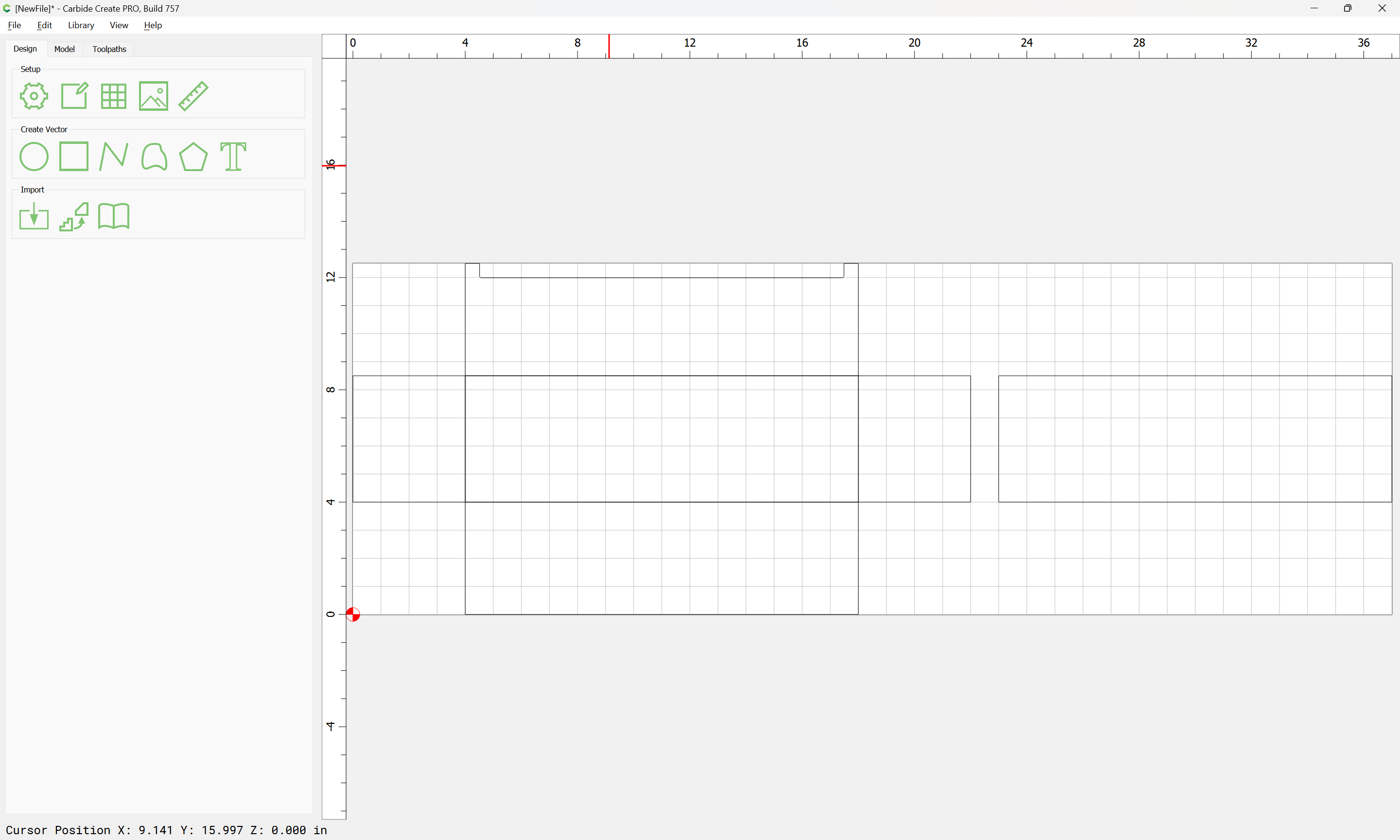
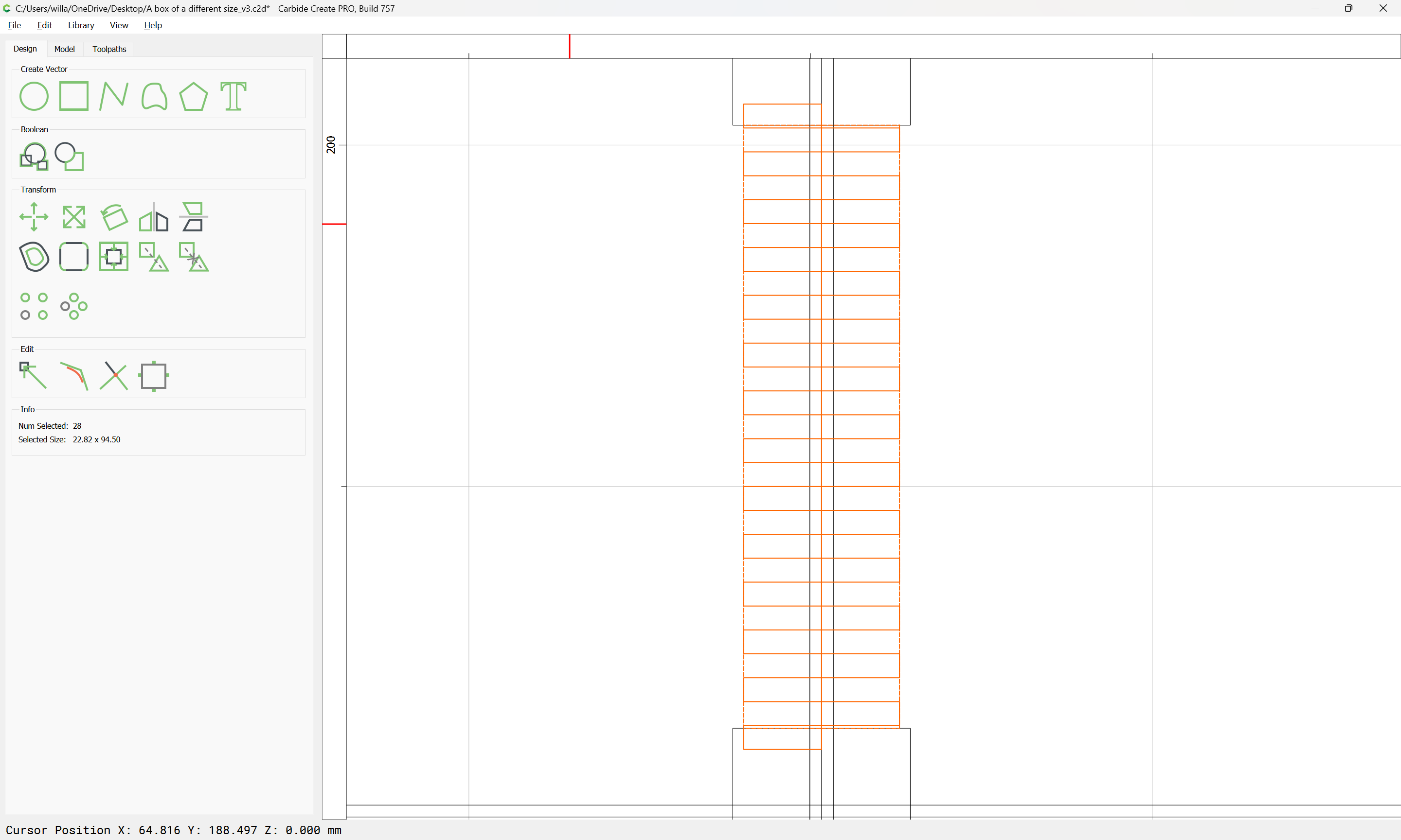
to center things:

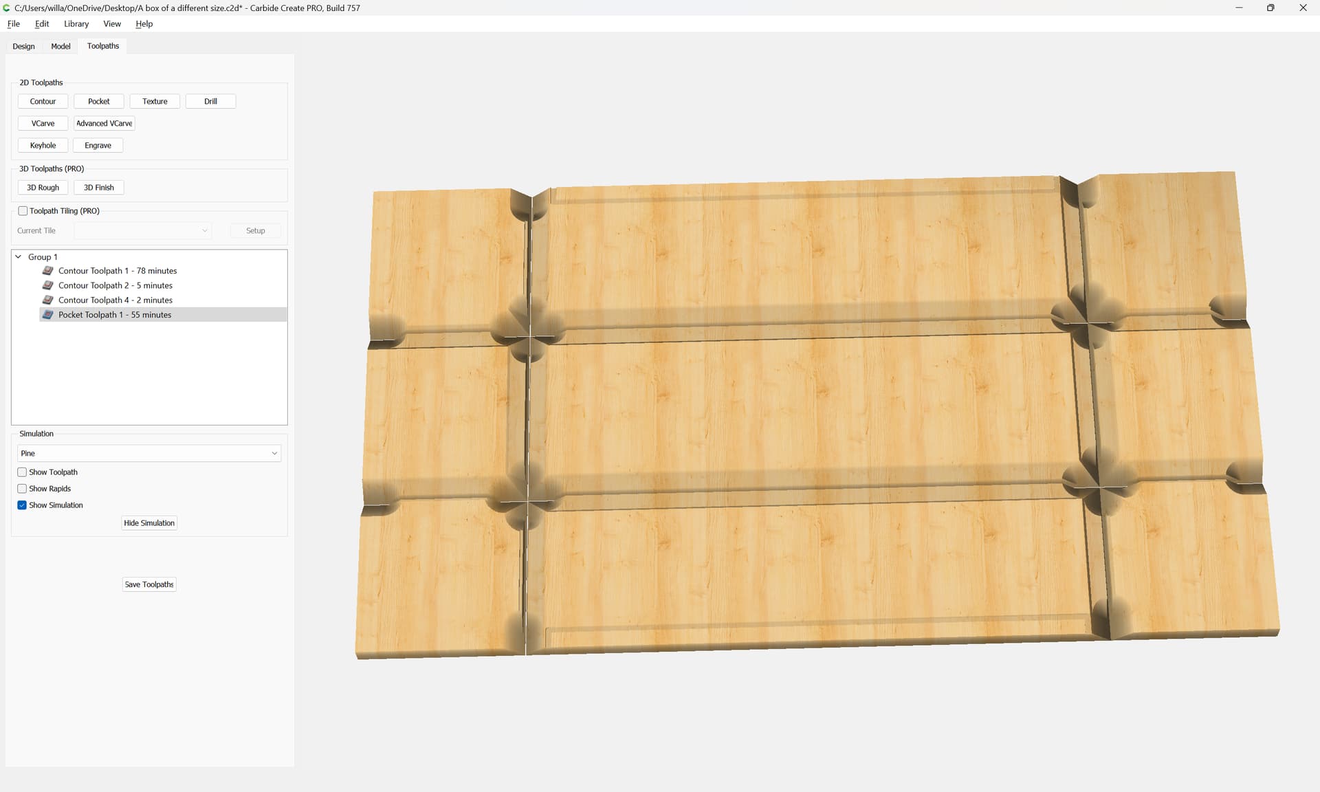
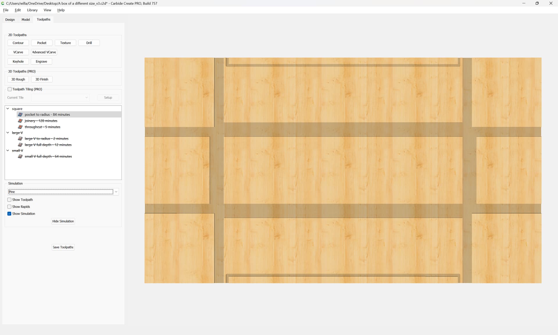
(it is better to overcut and create voids, then to leave material uncut which will interfere with fit — re-working the recesses and creating “biscuits” which can be used to fill such is left as an exercise for the reader)

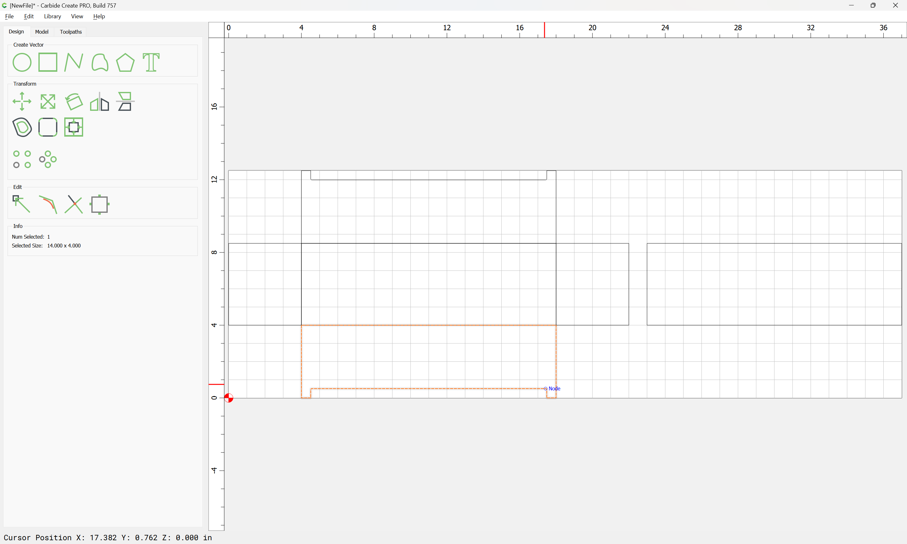
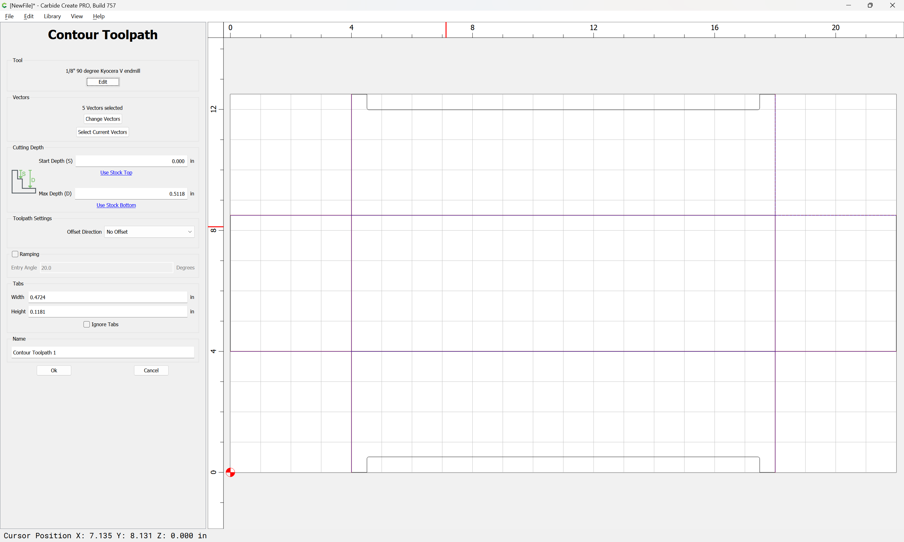
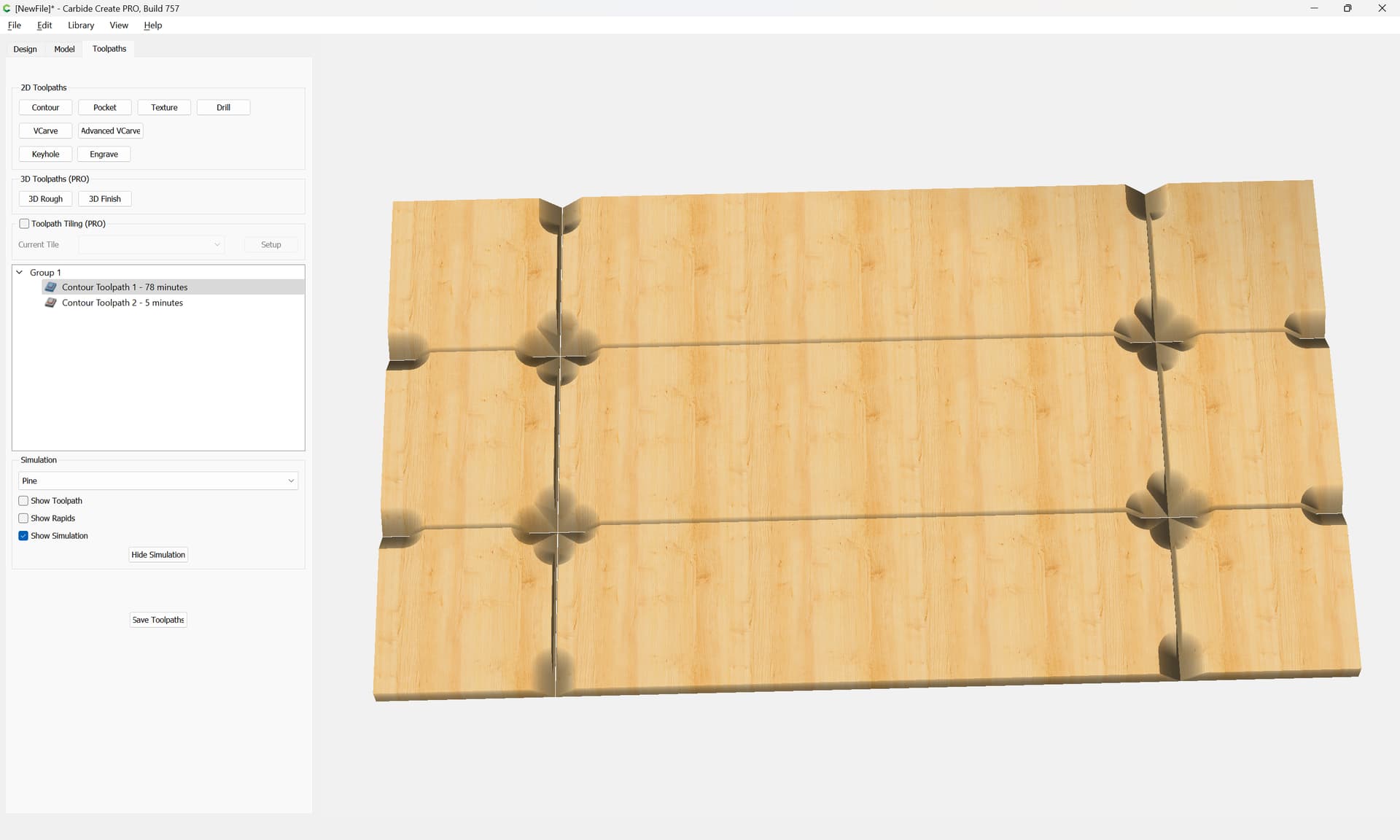
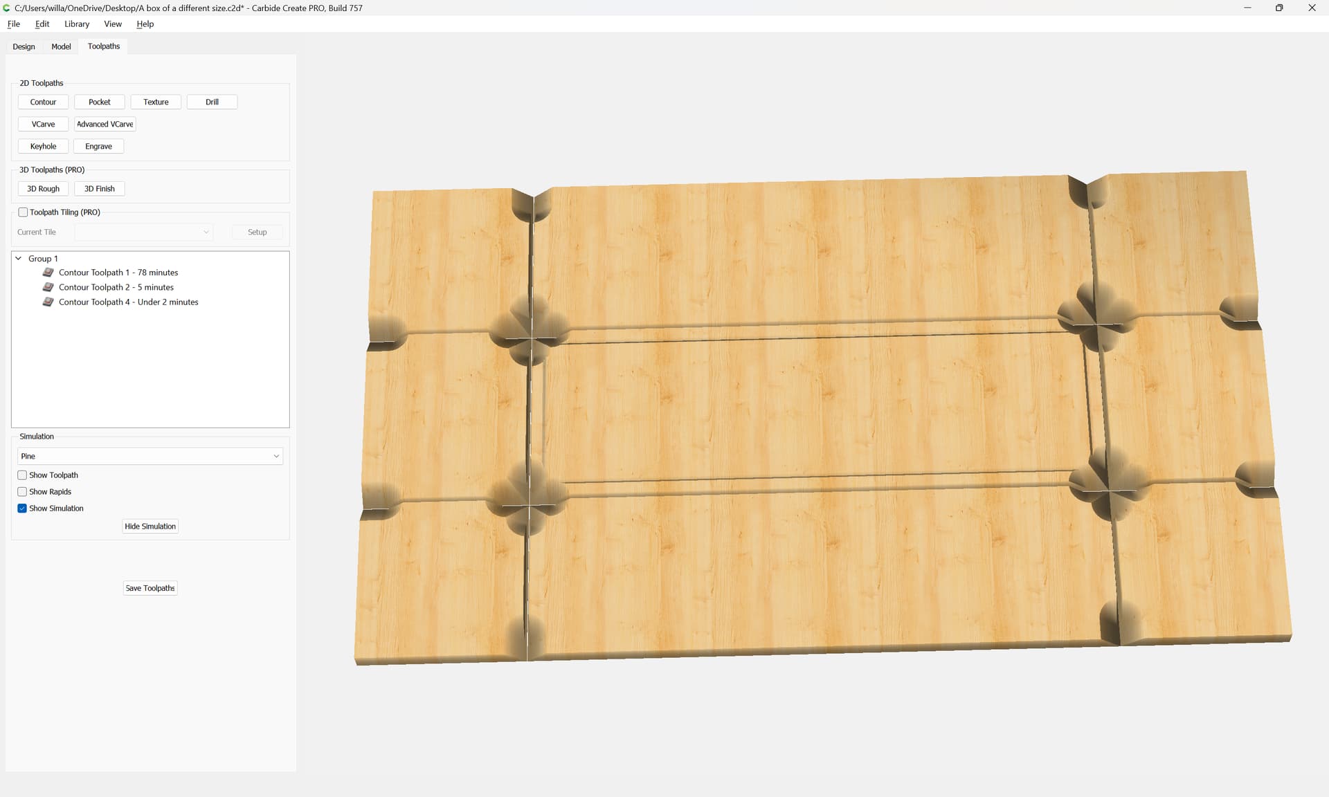
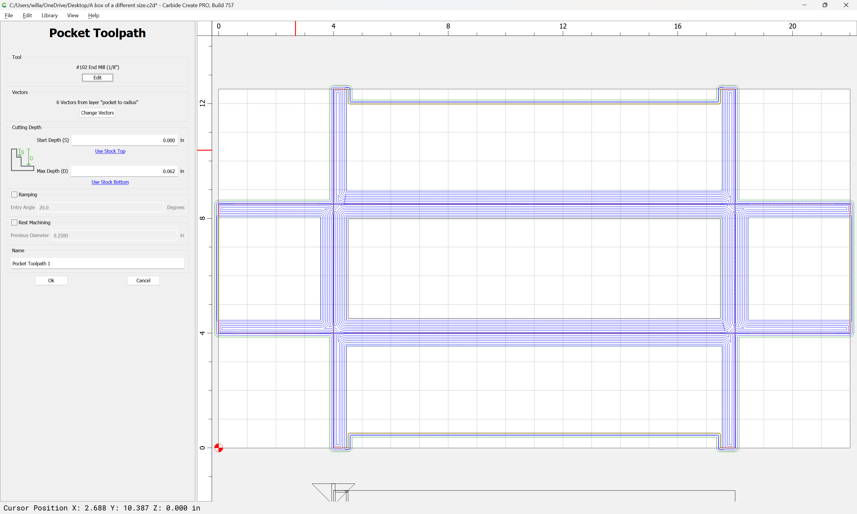
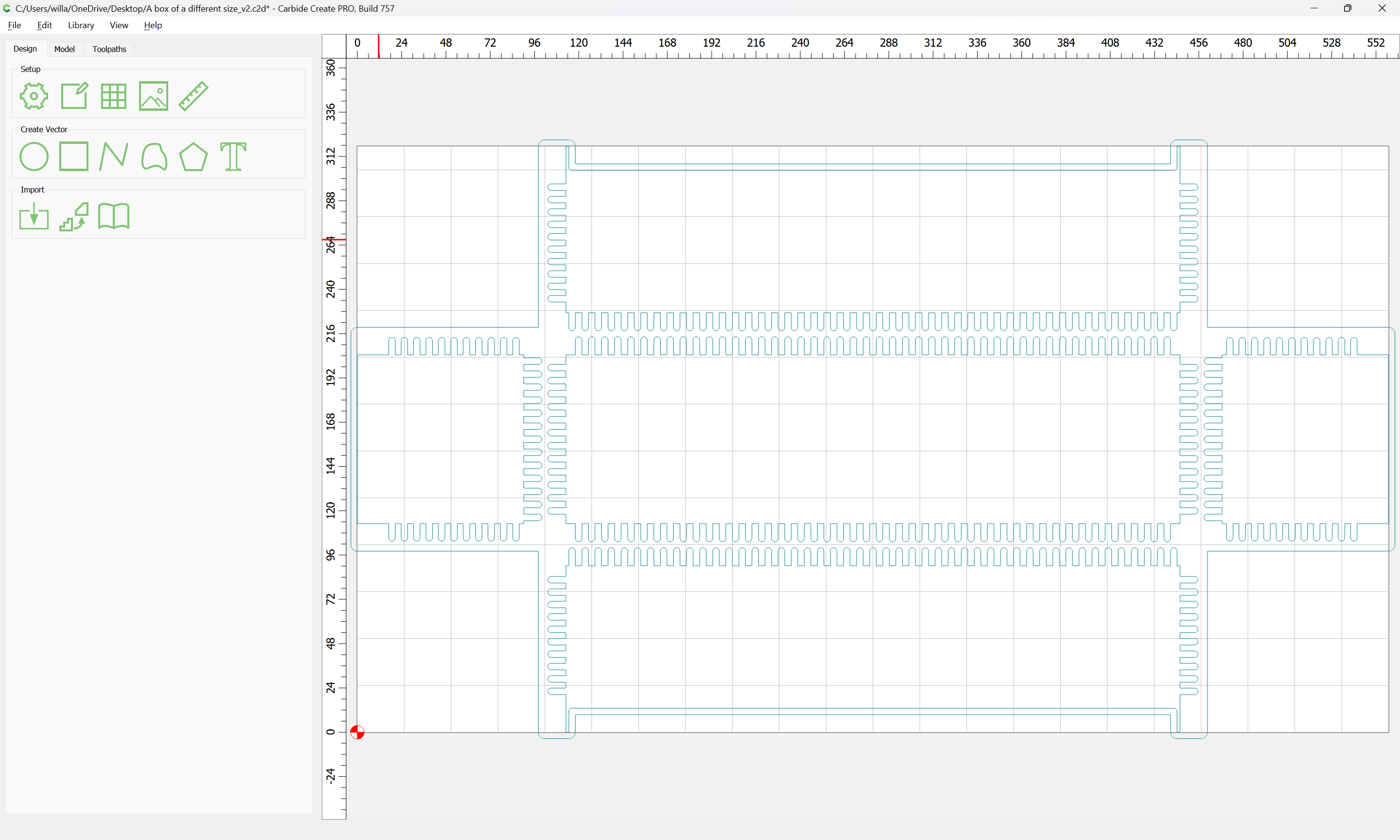
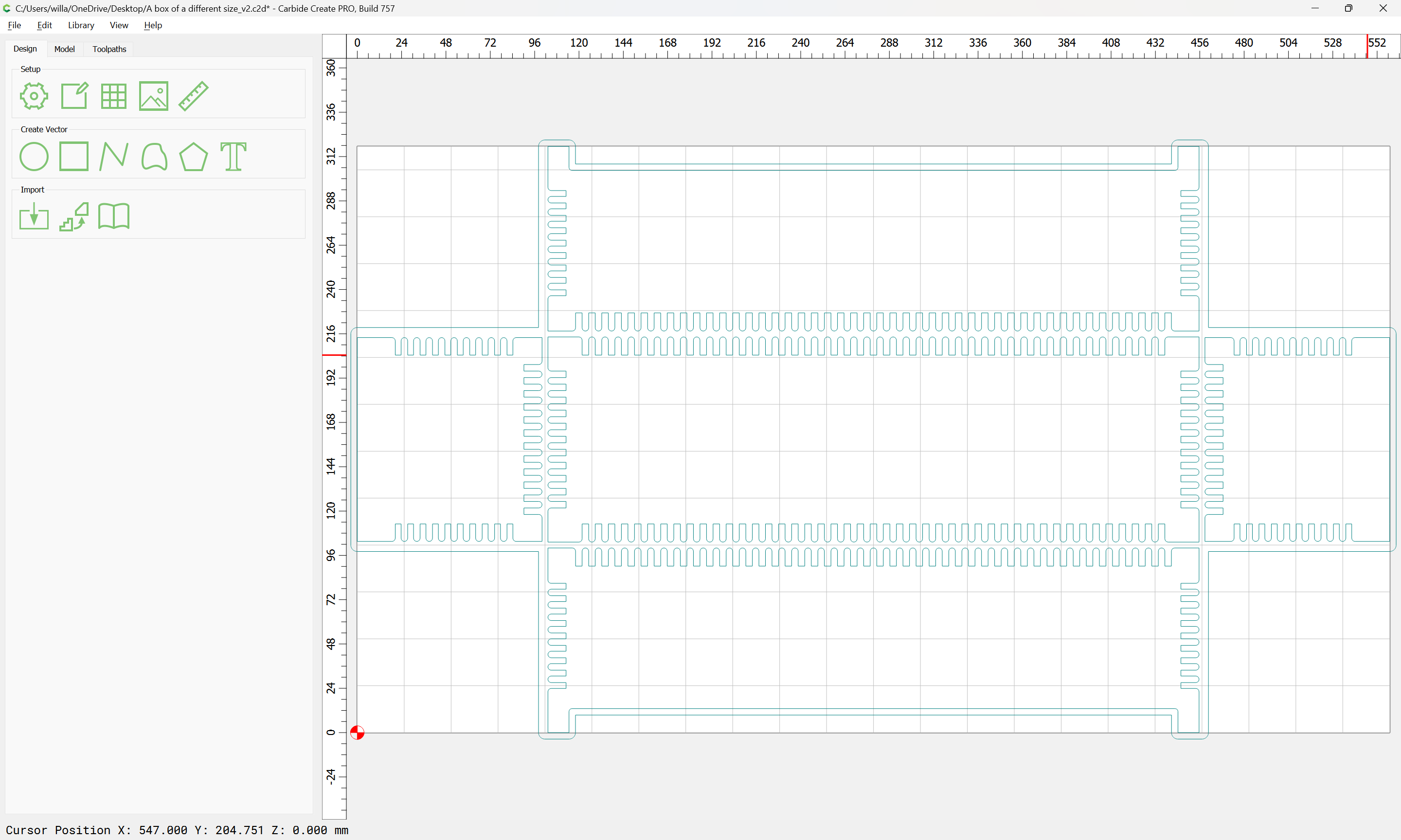
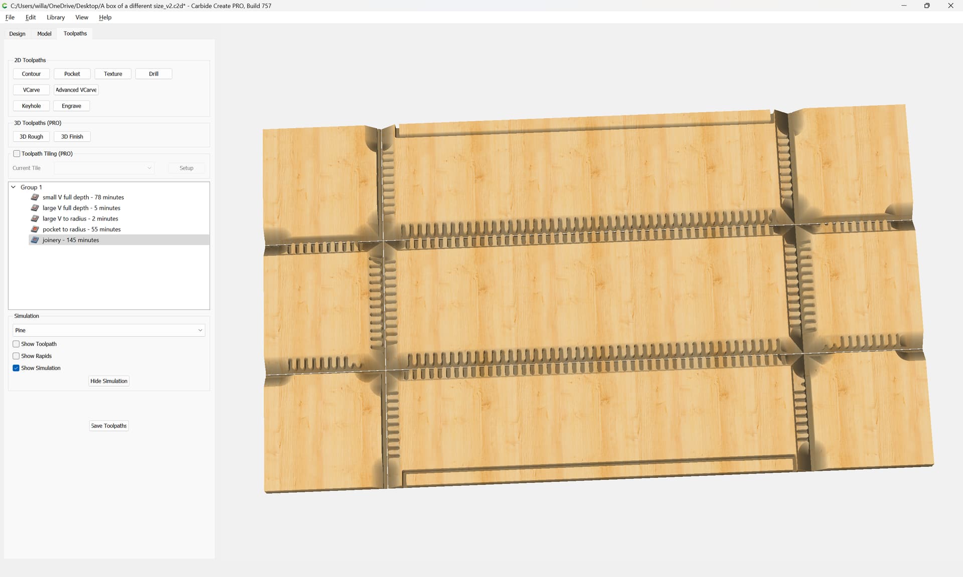
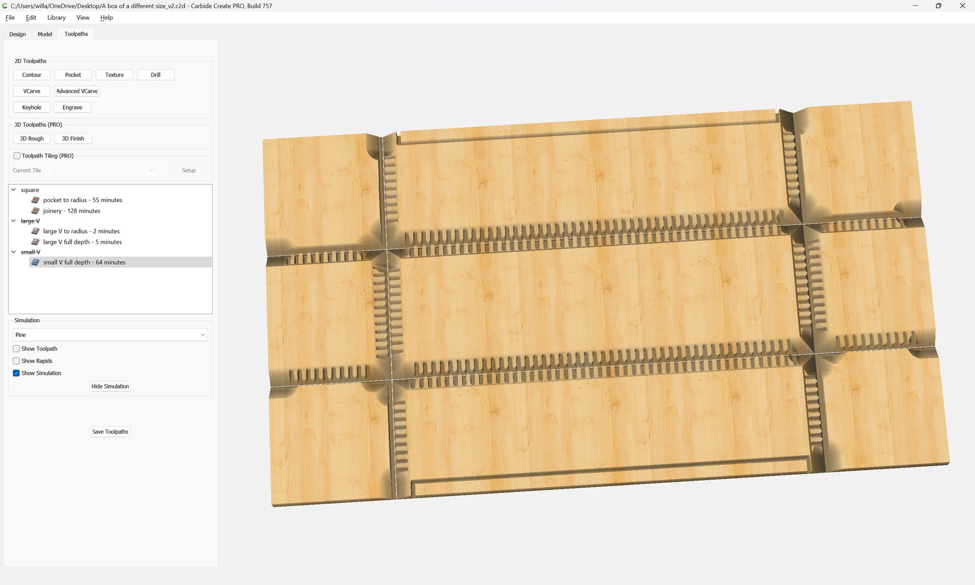
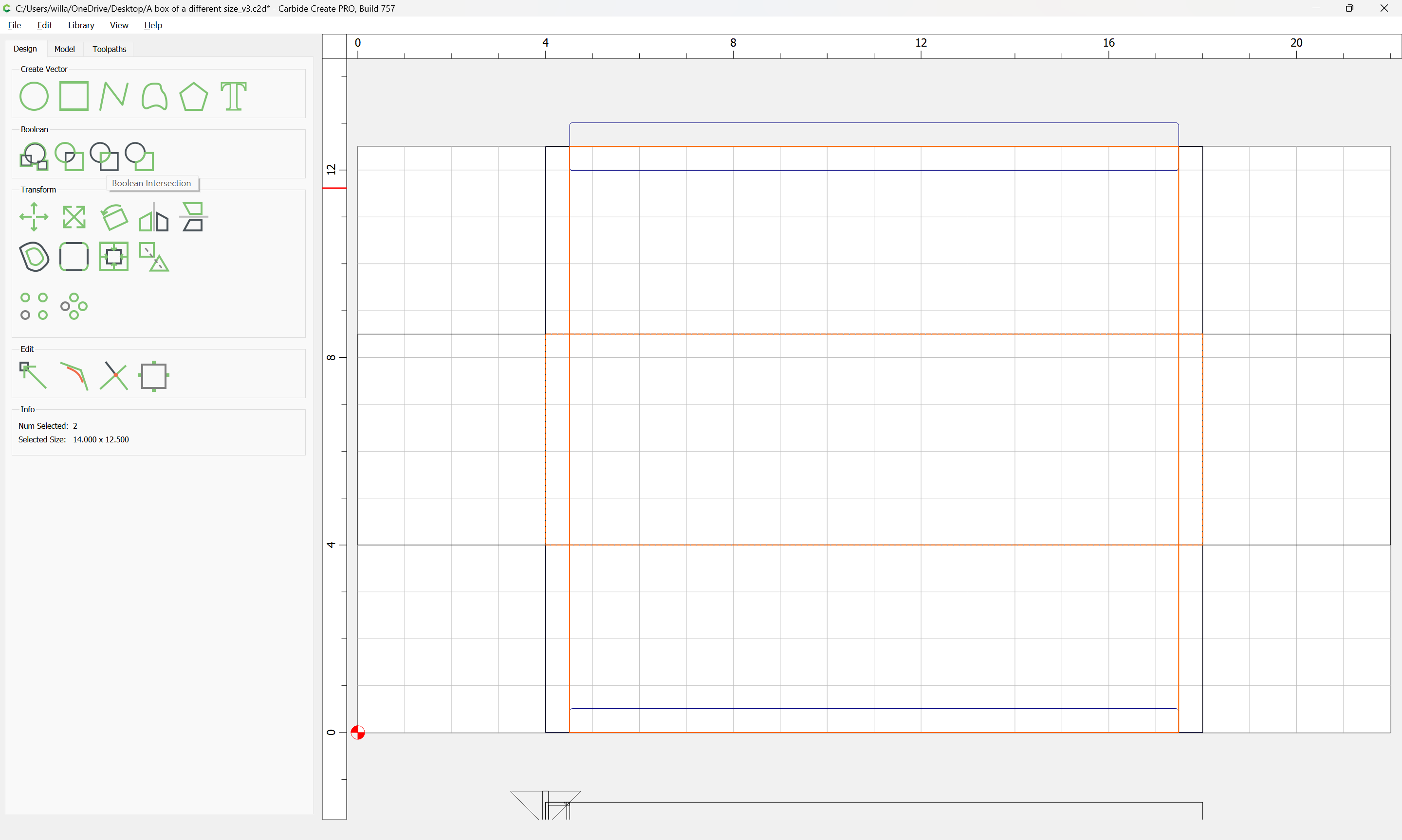
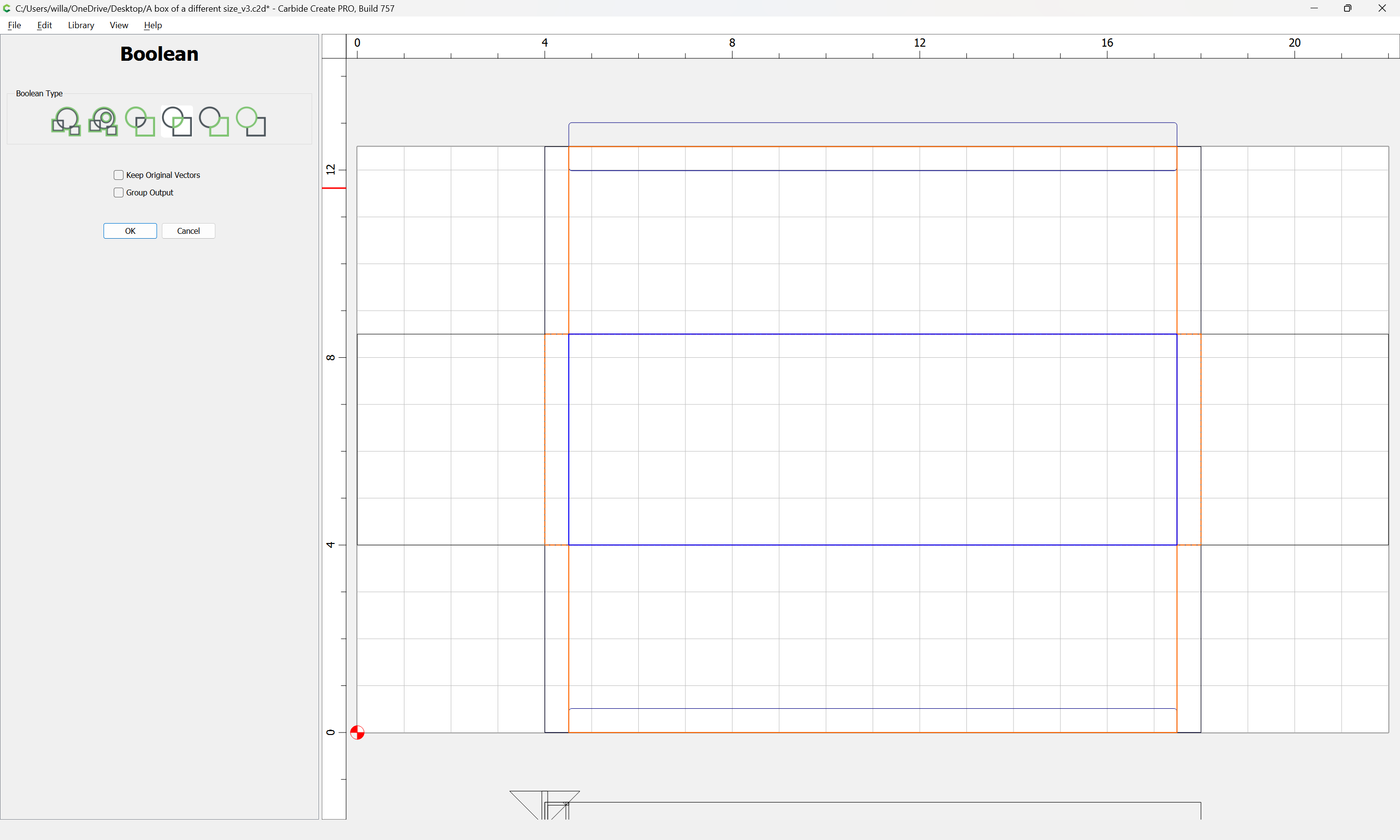
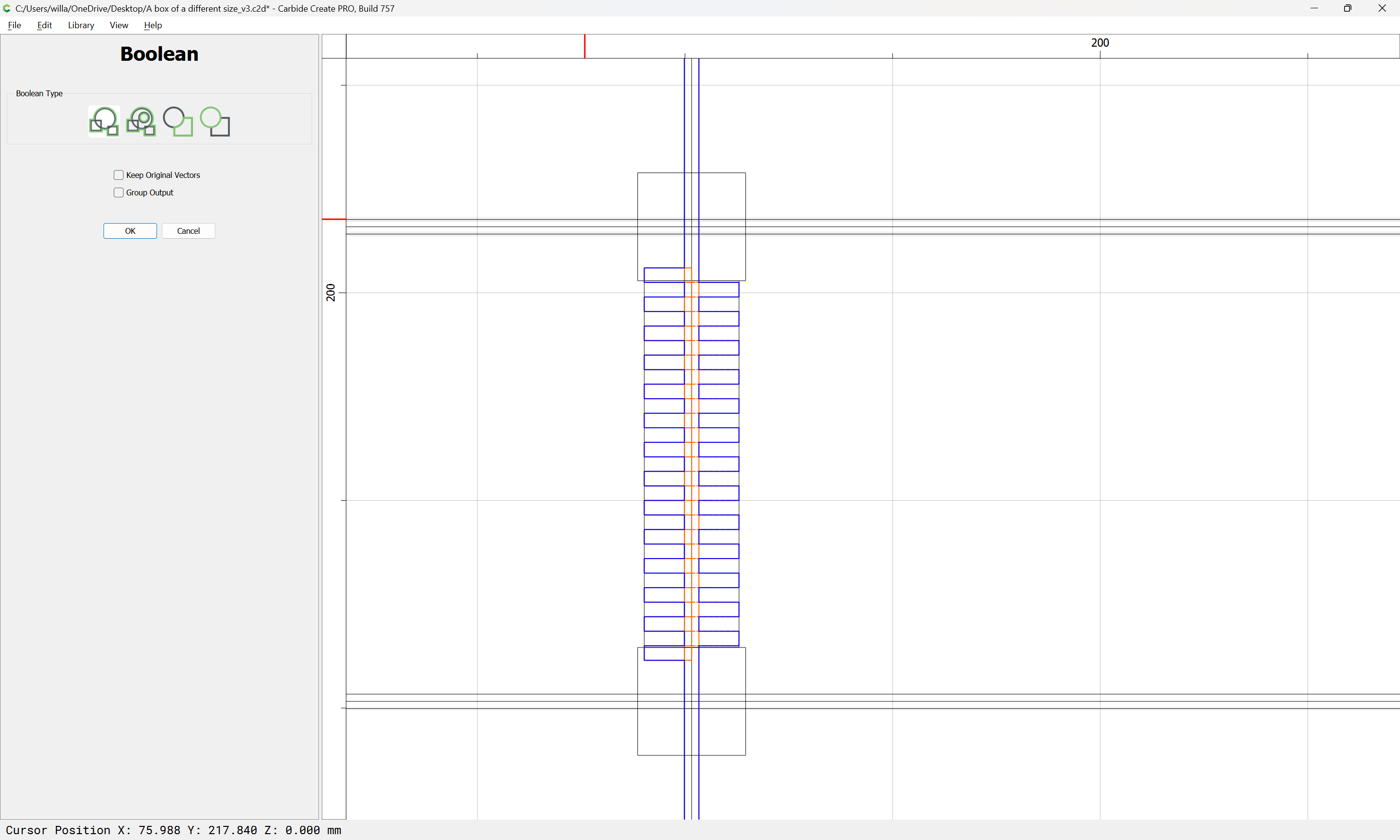
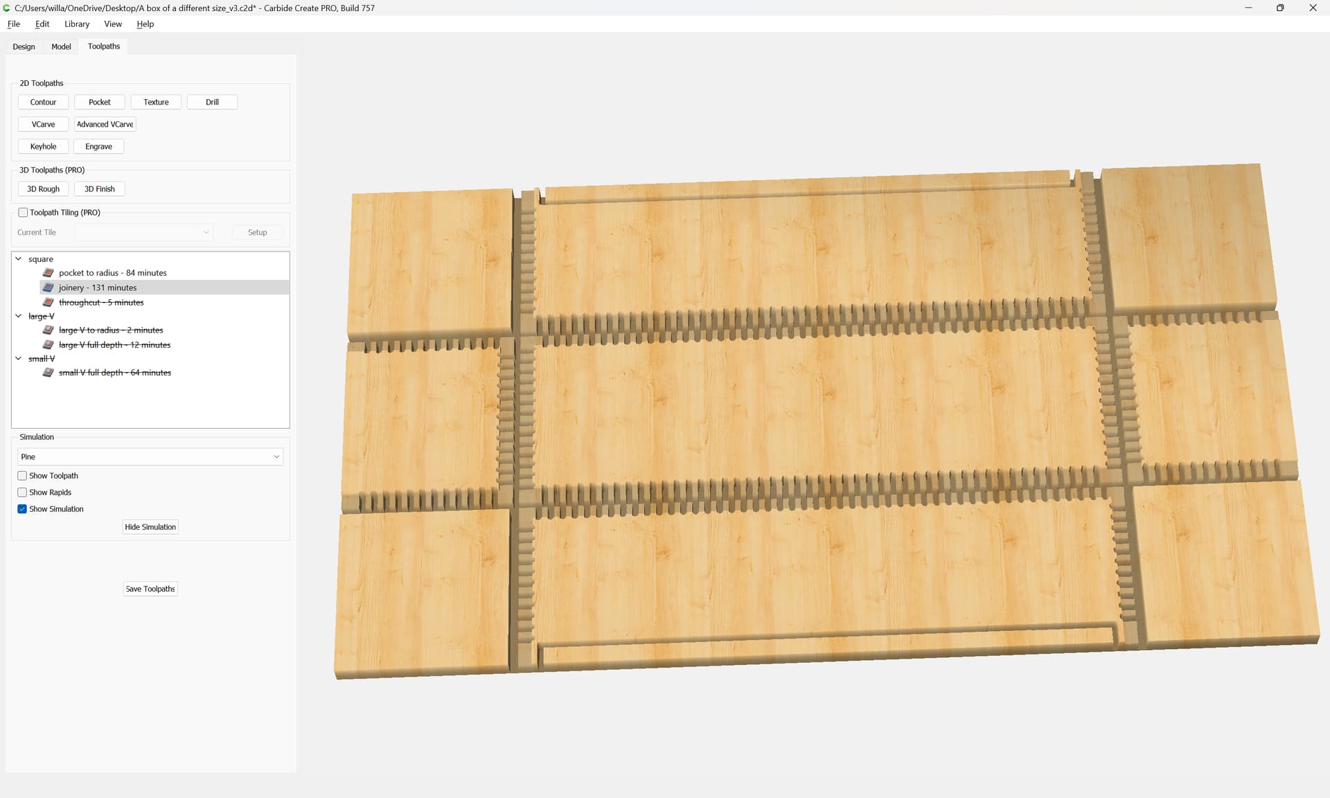
The joinery elements may then be Boolean Unioned with the central channel:

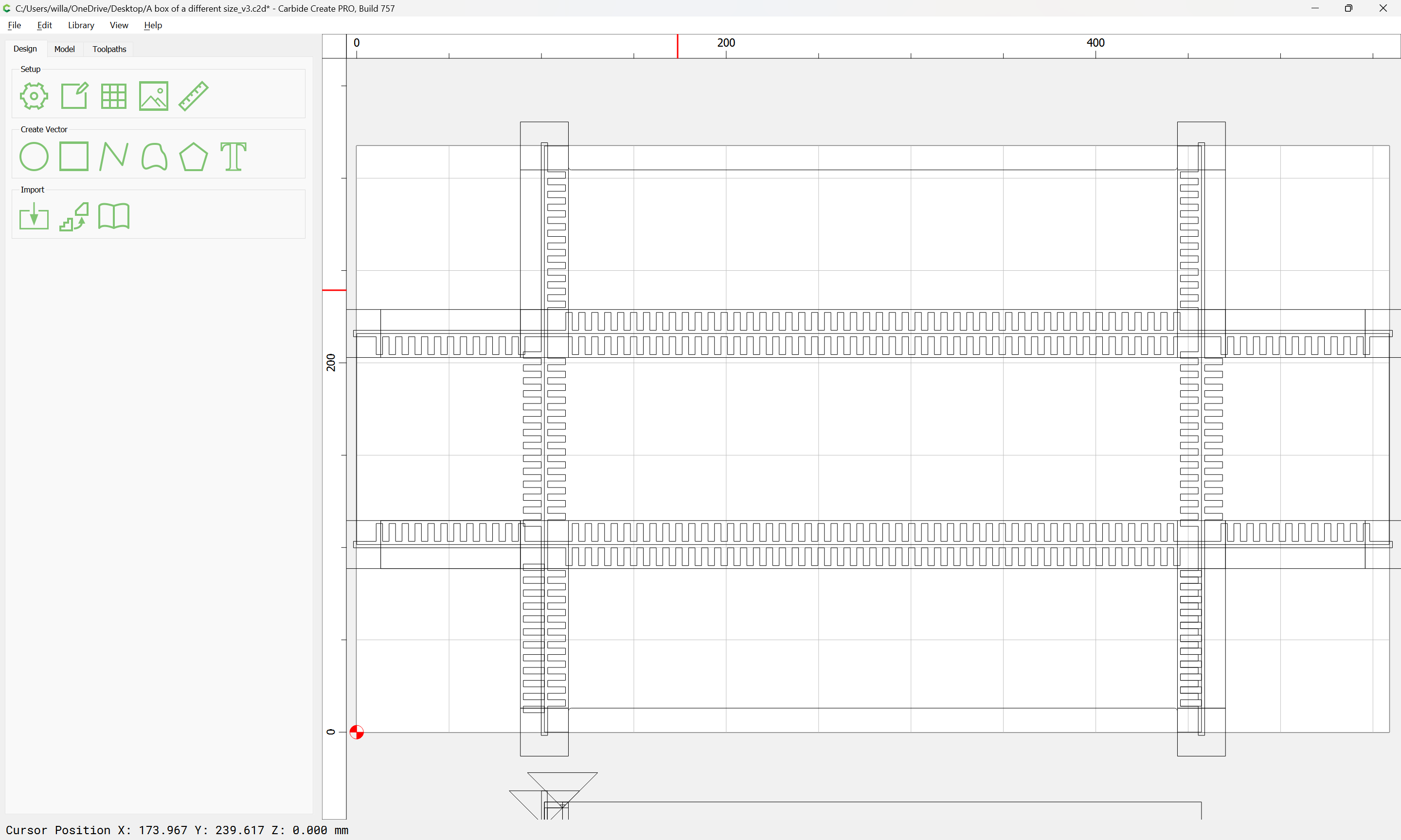
and this process repeated for each element of the joinery (note that for the sides meeting the front/back it will be necessary to rotate one or the other to bring them into alignment) — it is also recommended that one make everything consistent/symmetrical.

Eventually one arrives at:

Note that at some corners that an island is created — it is more straight-forward to leave such thus and to be careful during assembly/glue-up and to trust modern adhesives.

This geometry may then be unioned and moved to the appropriate layer for cutting:

Where one still has (or has copied over) the surrounding geometry.

Lastly, we add in geometry which defines the edges of the parts which are not involved in joinery (and check things and slightly rearrange/edit) to arrive at:

which now previews as:

I look forward to trying this when I have time to fully consume the concepts.