WillAdams
(William Adams (Carbide 3D))
March 4, 2020, 3:02am
20
To do this using the Advanced V carve features it’s much the same, just a bit simpler:
Set the texts and duplicate them and set the duplicates aside in case a reference is needed:
draw up the V carving geometry in profile to see how things will cut:
and offset the top geometry by that distance:
Boolean union w/ the outside geometry for the lower layer:
Where geometry has been lost, bring back the geometry which was used by repeating the offset (inset since we only need the counter) and dragging the original back into place:
Punch out the geometry using Boolean Subtract w/ the lower letterform outline as the key object:
Repeat w/ additional offsets and duplicates as needed until all details are included:
If need be union all script text together as noted at:
https://carbide3d.com/blog/merging-script-fonts-in-carbide-create/
Do an Advanced V carving with the upper text and the inner rectangle:
Inset the inner rectangle by the required distance:
and use it and the balance of the geometry for an Advanced V carving:
Attached.
shapeoko_adv_vcarve.c2d (791.2 KB)
2 Likes
Does advanced V carve work in the free version, or only Pro?
WillAdams
(William Adams (Carbide 3D))
March 5, 2020, 12:10am
23
It works in either license option for the versions released since then
2 Likes
Wow, thx so much for the great Tutorial William.
WillAdams
(William Adams (Carbide 3D))
December 24, 2022, 12:35pm
27
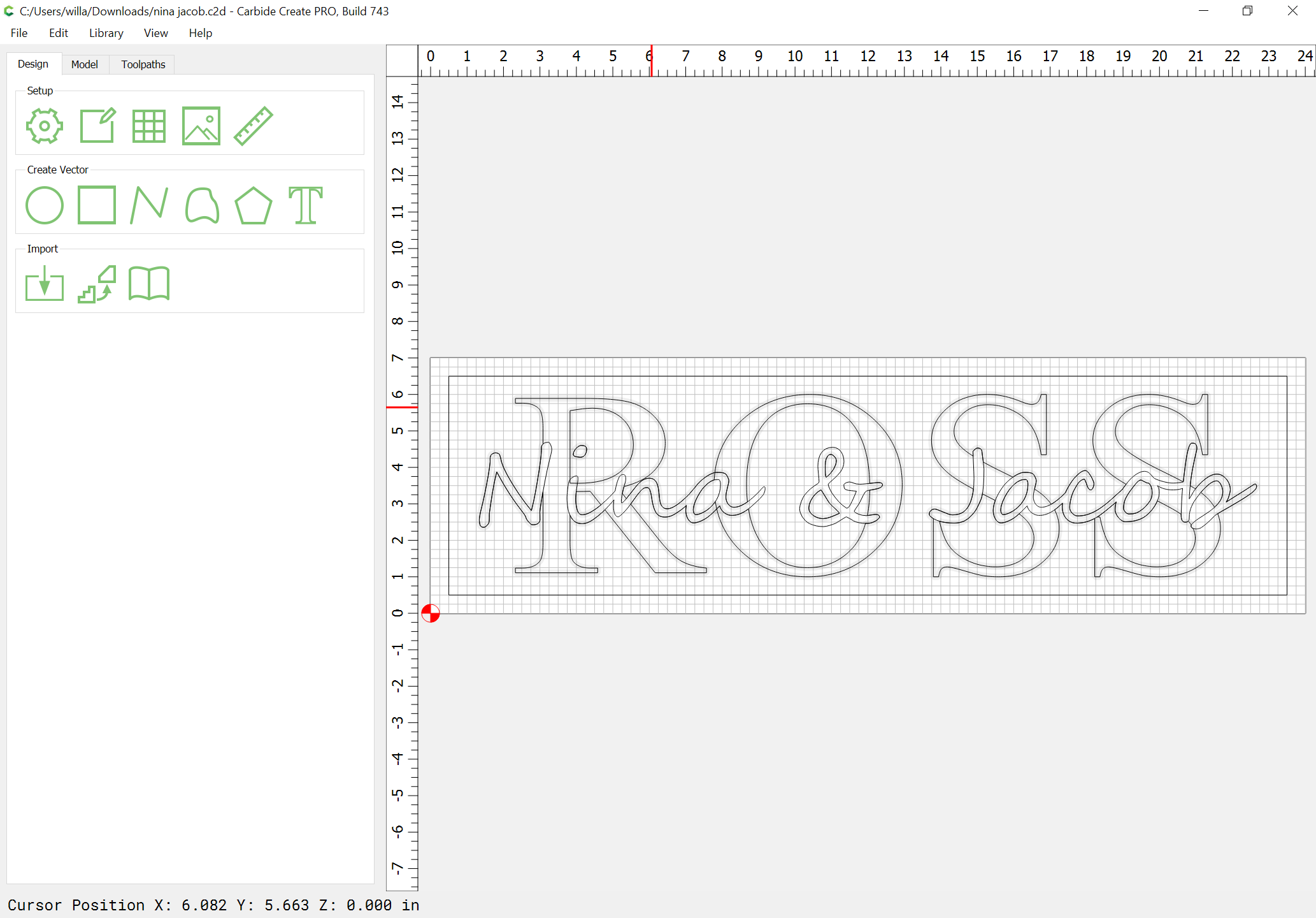
Here is another example, done on request from support:
which is to be cut to:
Material is .759"
Lower text .2" from top flat end mill
Upper text .1 from top. 60 or 90 v
WillAdams
(William Adams (Carbide 3D))
December 24, 2022, 12:44pm
28
The first concern is that some of the geometry is missing — the lower text is not showing through the counters of the upper text — this will need to be restored, and the entire design isolated as two layers w/ no confusing duplication.
Fortunately, the lower text is an only slightly distorted Times New Roman, so is easily re-set:
Convert it to Curves, snap it against the original:
select the original:
and delete it and create layers for each text and move them to the layers:
Duplicate all the text, move it to the Default layer, and lock the reference layers:
WillAdams
(William Adams (Carbide 3D))
December 24, 2022, 12:56pm
29
The difficult part for a multi-layer V carving is the offset of the lower layer — the upper layer is easily done:
but if the lower level is cut w/o being offset:
it will cut away the upper level:
resulting in distorted letterforms.
WillAdams
(William Adams (Carbide 3D))
December 24, 2022, 1:15pm
30
Draw things up in profile:
and do a Boolean Intersection to get the width which will need to be offset:
(or one could do the trigonometry to calculate this)
Select the upper text and the border geometry:
Inset them by the measured/calculated distance:
(note that including the border geometry will cause the inset to actually offset the text to the outside)
shift-click on the border geometry to remove it from the selection, and group the offset geometry:
shift click on the lower text to add it to the selection:
then Boolean Union:
Note that if using v7 or later, because both objects are grouped, the interactions of the lower layer w/ the counters of the upper layer is as desired:
shift-click on the inset border geometry to add it to the selection:
Apply an Advanced V carving toolpath which starts at the bottom of the previous pocket:
2 Likes
William,
Simply fill in edge a and angle b and hit calculate. Remember that angle b is one side of the cutter not the included angle of 60.
https://www.wermac.org/others/convert_right_triangle_calculation.html
1 Like
WillAdams
(William Adams (Carbide 3D))
December 24, 2022, 6:14pm
32
Nice!
I usually use:
and have added that link to:
2 Likes
WillAdams
(William Adams (Carbide 3D))
August 16, 2023, 2:41am
33
As requested on support…
First thing to do is to drag everything into registration:
and then use Trim Vectors to address overlapping geometry:
WillAdams
(William Adams (Carbide 3D))
August 16, 2023, 11:34pm
35
Eventually one arrives at:
The next consideration is what depths things will be cut to:
for a first layer which previews as:
has us then draw this up in profile:
and we need to offset by:
which we then union the text portion of with the C to arrive at:
to which we assign the toolpath:
which previews as:
1 Like
Stacked text is fun to do. I was messing around a made a video on how to do it for the beginner. https://www.youtube.com/watch?v=9HgGVBwj9X4&t=109s
Thank you.
WillAdams
(William Adams (Carbide 3D))
August 17, 2023, 11:50am
37
And if one gets the depths right, the appearance is spot on:
1 Like
WillAdams
(William Adams (Carbide 3D))
March 23, 2024, 9:21pm
38
If one has a file such as:
Then one determines the width of the cut:
and offsets the top layer by this distance:
Apply
and use Trim Vectors with this with the geometry for the lower layer:
&c.
until one arrives at:
OK
OK
Join Vectors
Yes
Then associate this geometry with the toolpath for the lower layer:
2 Likes
Bozo
(Bozo T Clown)
March 24, 2024, 1:41am
39
Not sure if it matters too much but a 60 degree v bit will not cut a groove with a depth equal to its width.
WillAdams
(William Adams (Carbide 3D))
March 24, 2024, 2:12am
40
That’s why one has to draw up the profile of the tool geometry/cut or do the trigonometry to determine the width/offset.