So I’ve made a few projects so far, and for each I’ve manually put in dogbones and such, but I’m aiming to do some more complex stuff now, and the prospect of intricately creating dogbones for each inner corner throughout the piece of furniture is super daunting.
Plus, I’ve come across some really interesting CNC-specific joinery options that look beautiful.
So I could probably manage to manually create some of these joints, but is the idea that one would manually put these all over a piece of work? Is there an automated way to do this? (ala a laser cutting box maker app or something)
I’ve seen people do vertical jigs for larger CNCs but didn’t think that’d be possible with an SO3(XL). I’ll have a look at that, as it would make a lot of this kind of work easier (to machine).
From a quick look through the links, it appears that most of these things export gcode straight up, so I guess the workflow for these things is that you just use the app or function and that’s it? (As opposed to create a project/body/component/etc… in Fusion and then applying things like this to them)
Actually, it’s the two commercial things which go straight to G-Code.
I’ve been looking at doing that with opensource stuff, but haven’t really found a tool which is a good fit for making G-Code and I prefer the idea of making a .c2d file.
Yes, folks who are willing to submit to being vulnerable to Autodesk’s licensing whims could do this sort of thing in Autodesk Fusion 360 (and it might be possible in Alibre Atom3D — I did one parametric design there), but that’s not me (for Fusion 360).
I will probably look into the 30 degree endmill idea, since the commercial product which does that is going away — I think I could use a similar fixture to the one I have planned for the blind miters w/ hidden splines.
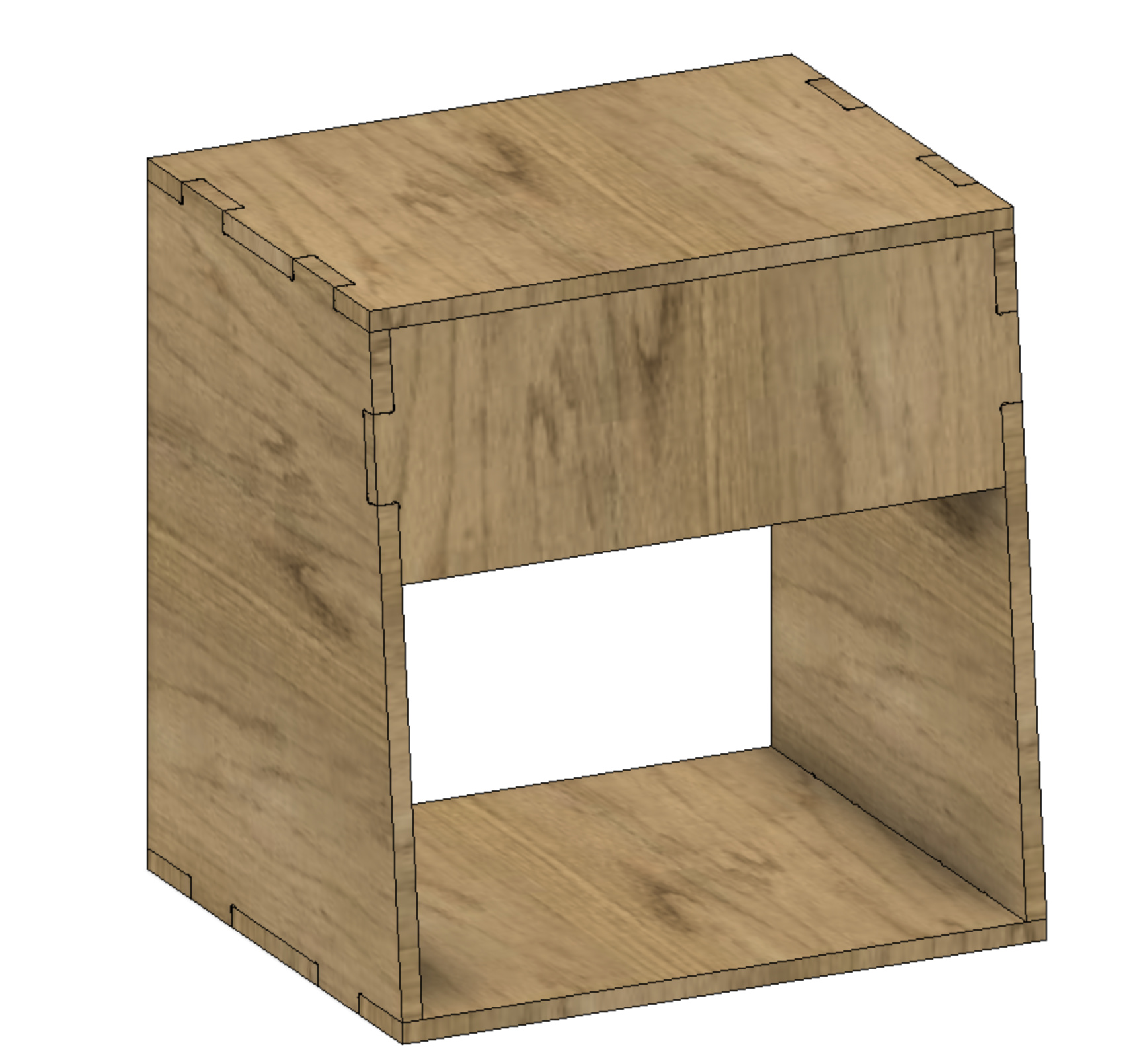
Pretty much finished the rabbeted box chapter — any comments or corrections would be welcome. Next up will be uploading the files to BlockSCAD, Thingiverse, and Cutrocket after cutting one myself.
Ah right, I gotcha. I’ve only really ever used Fusion with their free “maker” license, so I haven’t seen any of their whims, but being active in lots of music software worlds, I completely understand the reservations with massive corporations holding all the license cards.
Yeah, that’s what I meant. Generating some kind of thing which is then opened in an environment/editor (not as raw gcode). I’ve seen some things where you can run scripts in Fusion to automatically apply dogbones and such, but not run into anything more complex like this.
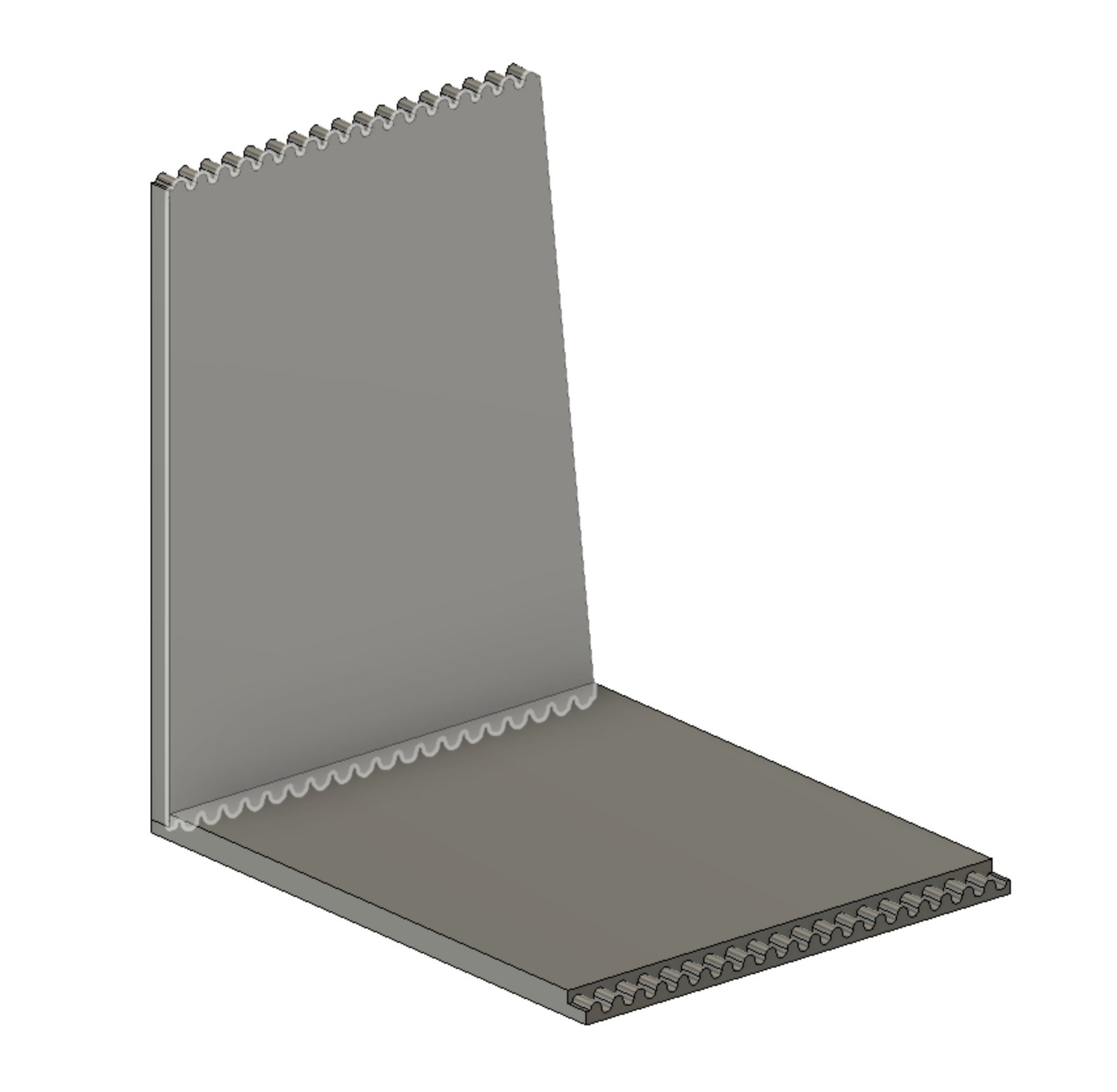
That Knapp joint stuff is quite interesting too, and fascinating that it’s actually an oldschool joint that can have a new life in this CNC world!
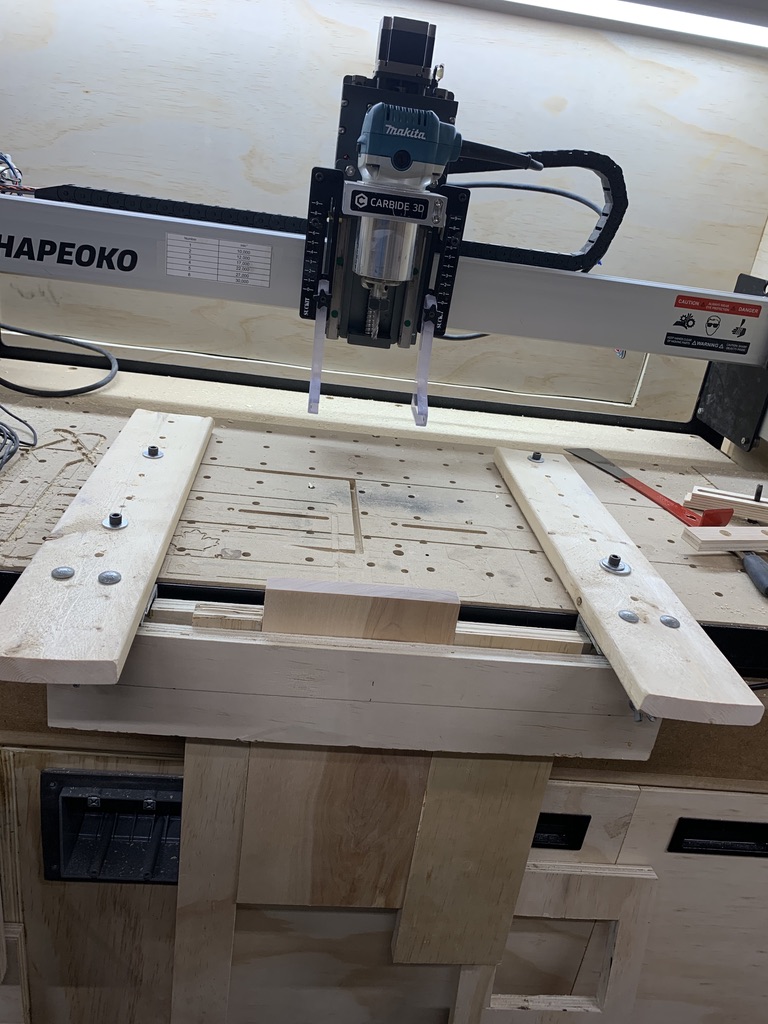
I used VCarve to create the Knapp joint. It took about an hour to make the fixture for vertical milling with leftover wood and hardware. It is not as fancy as the one made by @WillAdams but it is solid and accurate.
Huh, I really like your setup. I’d been lacking the desire to get a setup for joinery in place after seeing Richard Cournoyer’s right angle bracket jig out of aluminum.
This one looks simple enough to make out of MDF/plywood or aluminum and bracket it up without it needed to hang down a lot vertically. Thanks for sharing the picture!
It is really simple look at how it is made under. I use two metal angles (2"X2"), 4 bolts to hold those to the horizontal support (1"X4") that have holes to attach to my wasteboard, two pieces of 3/4in plywood to hold the workpieces attached with two 4in bolts with butterfly nut to attach them to the metal angle.
Do you find that it’s enough support when plunging down material? (vs something like @WillAdams’ approach that supports the wood from underneath as well with the crazy long bolts)
Well the only thing I can say is that I never had material move any time I used it. The only thing I would change is to use hardwood to replace the plywood to increase stiffness because as you see in the first picture, I had to place material on either side to ensure the plywood stayed flat. I did not have any spare hardwood properly sized when I built the fixture.
I will note that I expect the wood to be held in place by clamps at the top (I ground off a couple to fit, and sourced a few more intend for clamping as stops which I need to fabricate some sort of bracket for) — the threaded rods and speed nuts and bottom support are simply to allow consistent positioning and easy adjustment of board positioning.
Those should be trivial — just mill out a series of pockets or V carvings which are periodic along the length of the axis — try drawing one out and doing a test cut in a scrap of material — if it doesn’t work, post your file and a photo of the results and we’ll do our best to work through it with you.
I actually modeled a bunch of it manually (which was a bit of a pain) before realized I wouldn’t be able to cut the geometry from the base (before I saw the stuff about a vertical joint).
My design is using 12mm stock, and roughly 400(height), 380(width), 310(depth(base)).