The folks at Carbide3D announced a new beta feature in Carbide Create: Layers.
This tutorial gives this new feature a spin using the beta version, to make a stacked-text sign. I’ll try to make this an entry-level tutorial (screenshots for every small step) for those who are relatively new to CNC and want to make their own stack text signs.
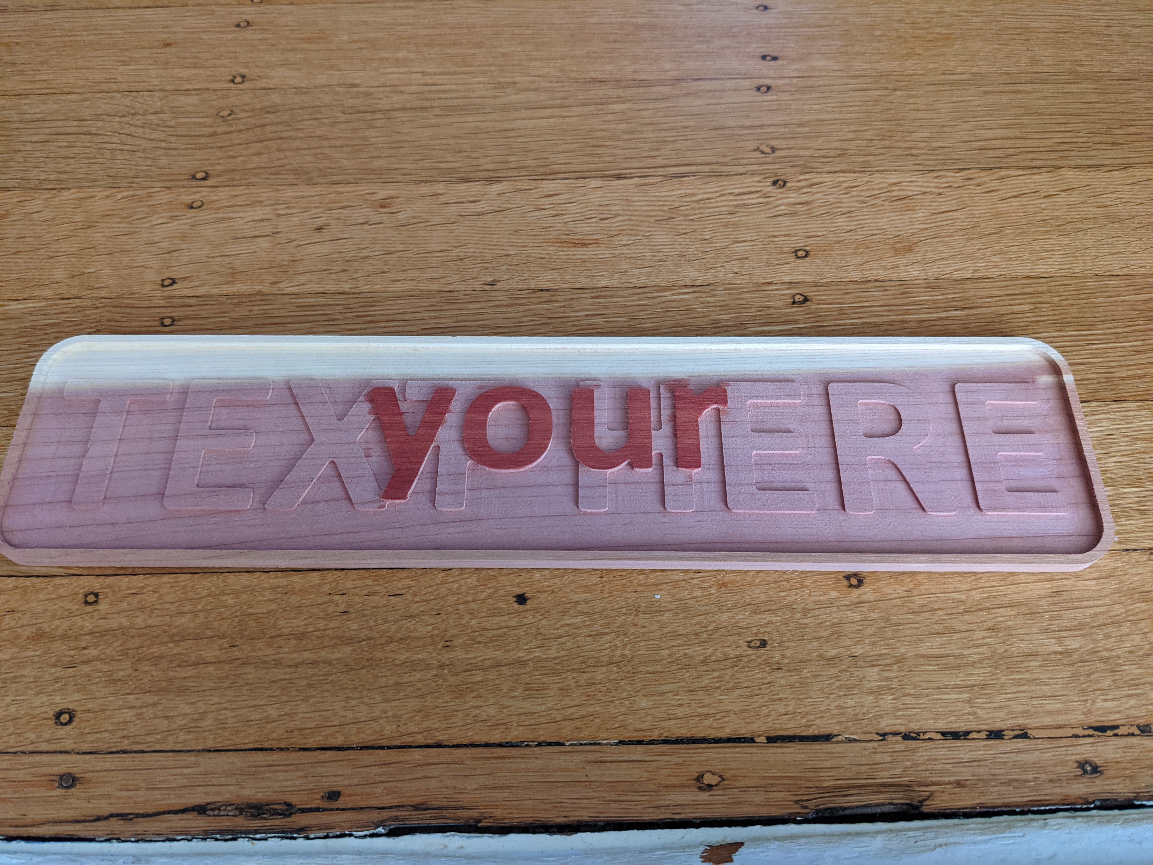
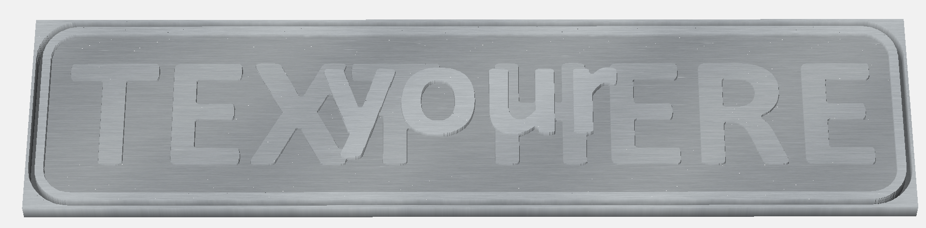
For the example I’ll stack “your” on top of “text here”… since that’s boring in general you should replace that with the text you want to use…
Material & Bits:
I am going to use a 12" x 3" x 0.25" piece of wood; these are easy to find on ebay (just search for ‘12" craft boards’) in various wood species and are a great size for various signs and are thick enough to not warp while being cut.
I’m also going to use a 2mm downcut bit (https://smile.amazon.com/gp/product/B073TXC45Z, not an affilate link). A 1/16" bit will also work; for cutting text at this size, 1/8" or 1/4" is going to be too coarse to get a good result.
Step 1: Basic job setup in Carbide Create
We first need to tell Carbide Create how big our material is, and for this, select the “sprocket” at the left top:
This opens the following dialog, into which I’ve already filled in the dimensions of 12 x 3 x 0.25:
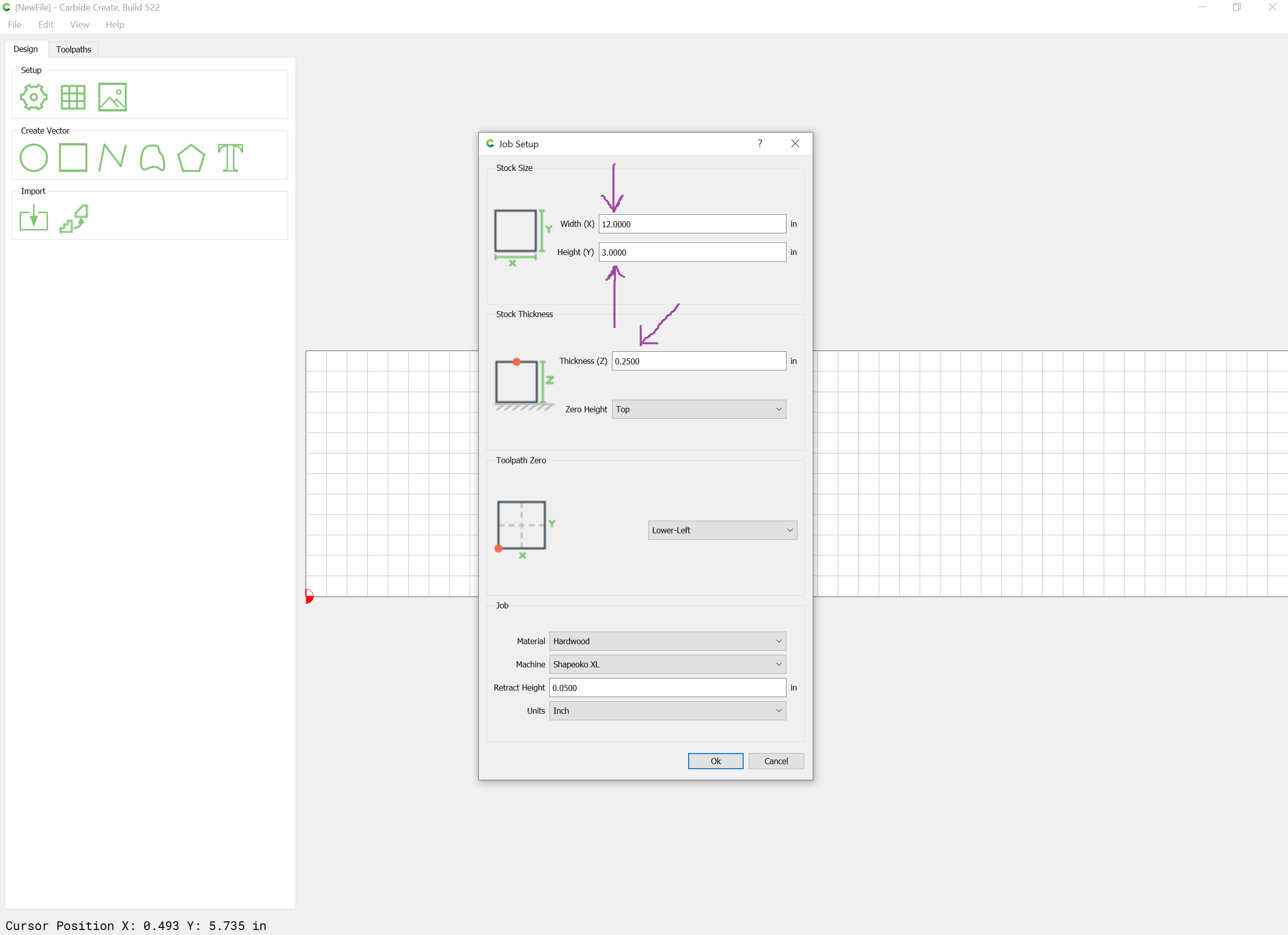
Also make sure that the usual settings for “Zero at Top” and “Lower Left” are selected for the Tool path Zero
Step 2: Creating the layers
For this project I’m going to use 3 layers. The “top” layer will be used for the outside layout of the sign.
The second layer I will use for the word “your” (which is the top most word" and I’ll use a third layer for the words “text here”.
Use the “L” key or the Edit menu to open the layer dialog box, which looks like this:
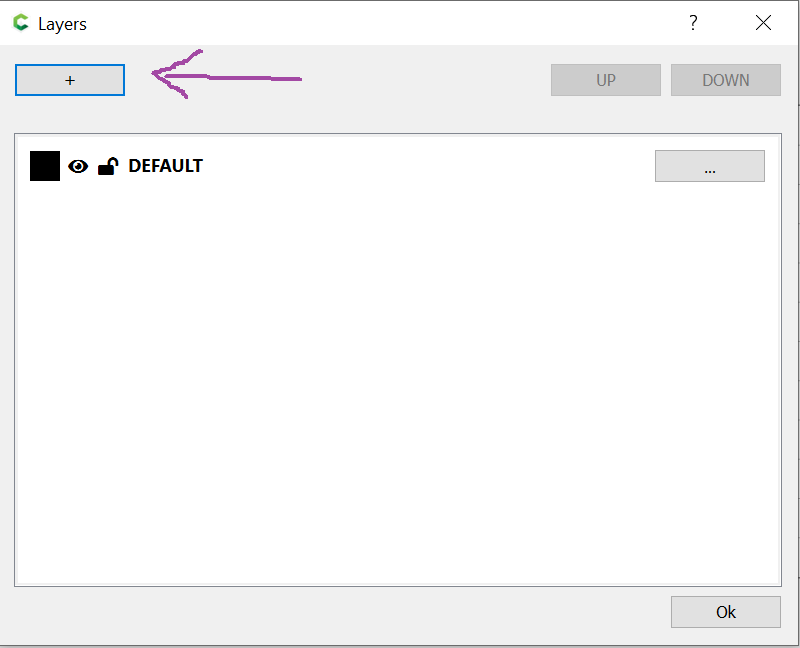
Using the “+” button on this dialog, add a layer named “your” and then again, a layer named “text here”.
(it’s a good idea to name your layers to what you want to put in the layers"
As of version 524, each layer with have a different unique color, but you are free to change these. To change the color of a layer, click on the square in front of the layer:
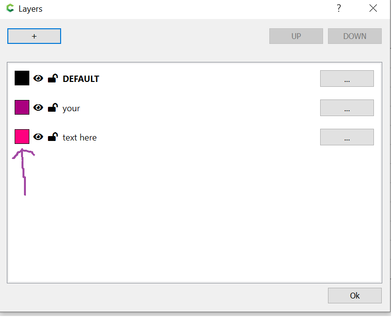
You can pick any color you like, but in general, darker colors work better on the white background, and it’s best to stay away from orange as that is the color used for selections.
We’re – for now – done with the layer dialog, so once you’re happy with the colors, click the OK button.
Step 3: The outside frame for the sign
To give the sign the nice rounded corners, we’re going to add an outside frame. I usually make this frame 1/4" smaller than my material leaving 1/8" all around it. This 1/8" is there to compensate for any small variations in size of the wood I bought, and, more importantly, for any slight angle I might put the wood on my shapeoko. (yes I’ll try to put my stock on the machine perfectly square… try being the key word).
So for this sign that means 11.75" by 2.75".
To do this, we use the “Create a rectangle” button in the “Create Vector” section:
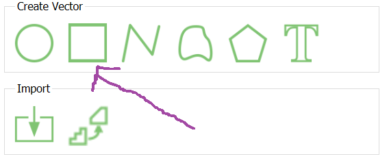
This will ask you to draw your square… do not worry about the details of size, just click on the work in one place, and then click a bit away from that, to finish the basic setup of the square.
The actual size of the square we’ll set up by typing the dimensions:
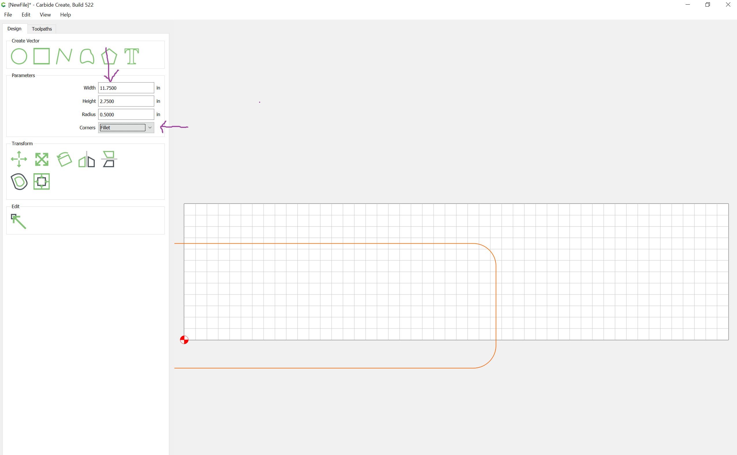
In this case, 11.75 for Width, 2.75 for Height.
We also want a nice rounded corner, so pick “Fillet” for the “Corners” option (see the arrow I drew in purple on top of the screenshot). With this, you can set a radius, and I tend to like 0.5" for this, but really, anything from 0.25" and up will work.
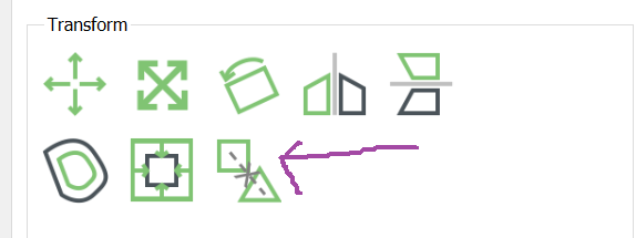
With this done, the rounded-rectangle is not in the middle of the design yet, so we’re going to do that next using the alignment button:
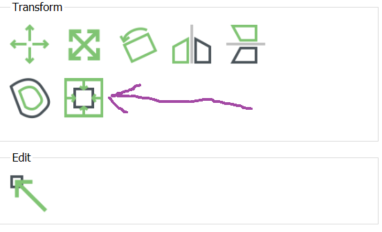
This opens up the alignment screen, and we’re going to align the rectangle to be centered in all directions:
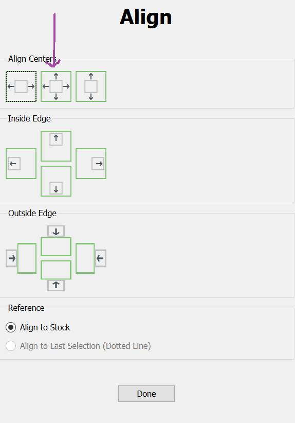
Our rounded rectangle should now be perfectly centered in the work area with 1/8" space around it.
Throughout this tutorial we need to align a few more things to be centered in all directions; I’m not going to repeat the screenshots for this… it’s exactly this same step.
To create a nice “ridge” around our sign, we are also going to need an inside frame, so we’re going to create that next.
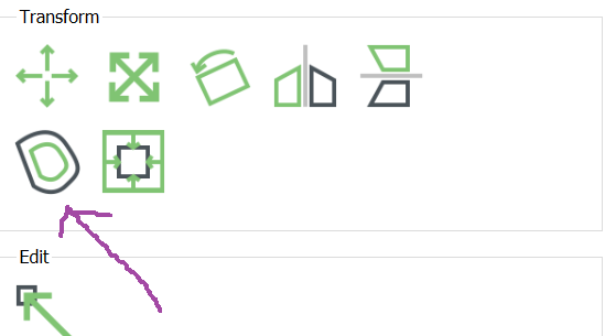
For this, we click the “Offset Vectors” button, which will allow us to make a rounded rectangle perfectly inside the outside frame;
To create a 1/8" ridge around our sign, we’re going to create our inside frame 0.125 inch on the Inside of the outside frame rounded rectangle:
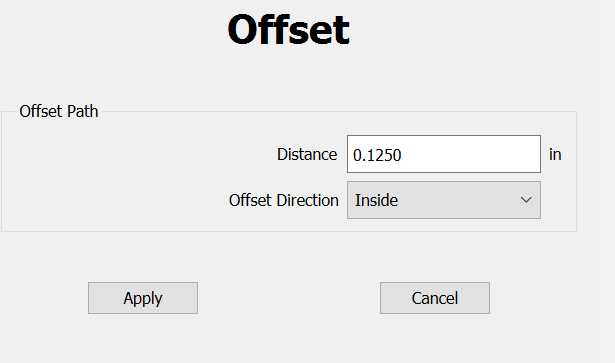
and hit apply.
At this point your design should look like this:

Step 4: The “your” text
With the frameing done, it’s time to start the upper part of the stacked text, the word “your”.
Before we do anything else, we want to switch the active layer so that the work on “your” is done in … the “your” layer.
Do this by hitting the “L” key (or select the layer option from the edit menu). This will open the Layer dialog screen:

For the “your” layer, click on the three dots to get the options for this layer:
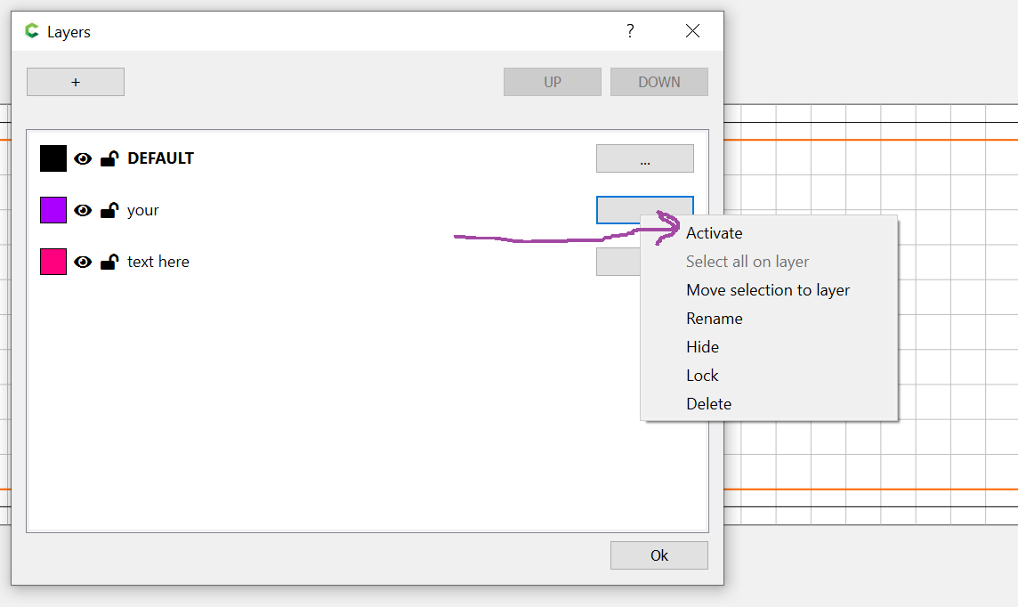
And select the “Activate” option.
All changes you do will be done to the layer that is active (bold). Now that the 'your" layer is active, click the “Ok” button to go back to the design screen.
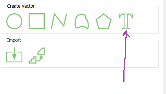
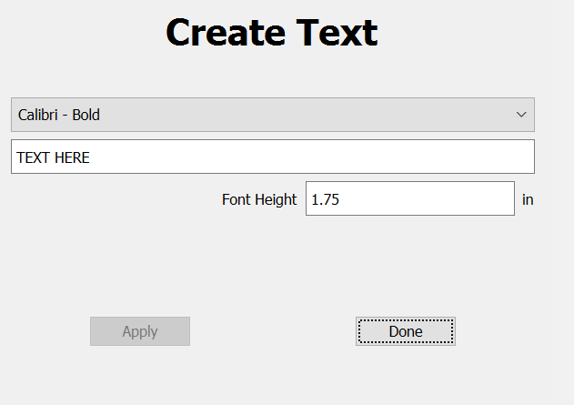
To add the text, we use the “T” for Text icon:
Pick a font you like, and change the text to “your” and the size to 1.5":
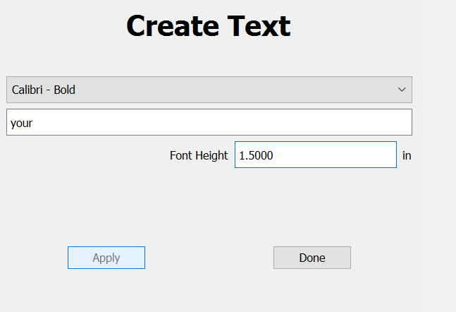
Don’t worry that the text on the design is not centered yet, we’ll center it next.
I picked 1.5" for the size since this is the top layer text, and stacked designs often look better with the top text a bit smaller than the lower layer text (which we’ll make 2" heigh).
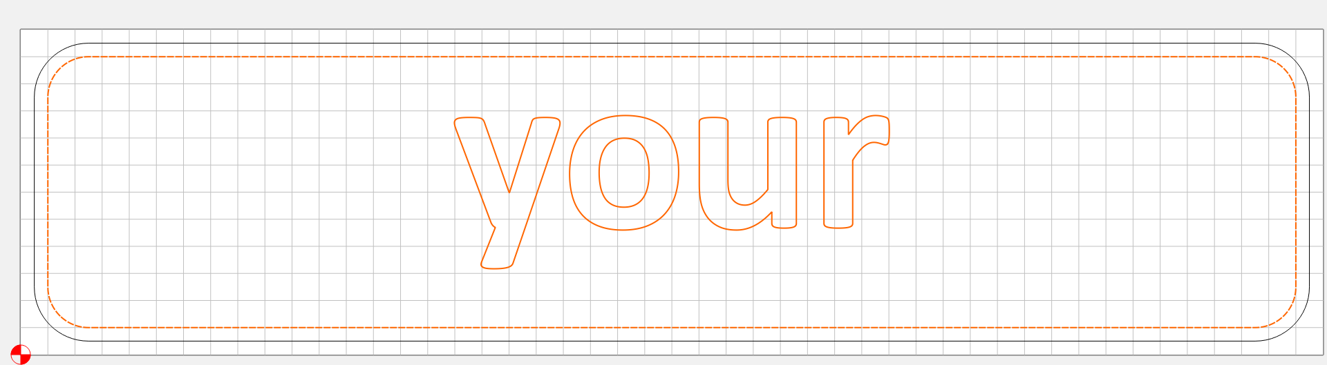
Hit the done button and we’re going to center the text again using the Alignment button like before:
Make sure the word “your” is selected (orange) when doing this.
(I’m not going to repeat the rest of the center operation, you’ve done this before in step 3, just follow the exact same steps)
Step 5: Toolpath for the “your” text.
We are now going to make the toolpath for the first layer of text.
First, make sure that the word “your” is selected (colored orange). If it’s not just click on it to select it.
Next, hold down the Shift key and click on the inside frame rectangle we made in Step 3.
The work area on the screen should now look like this:
with both the inside frame and the text “your” colored orange.
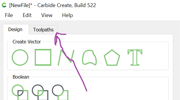
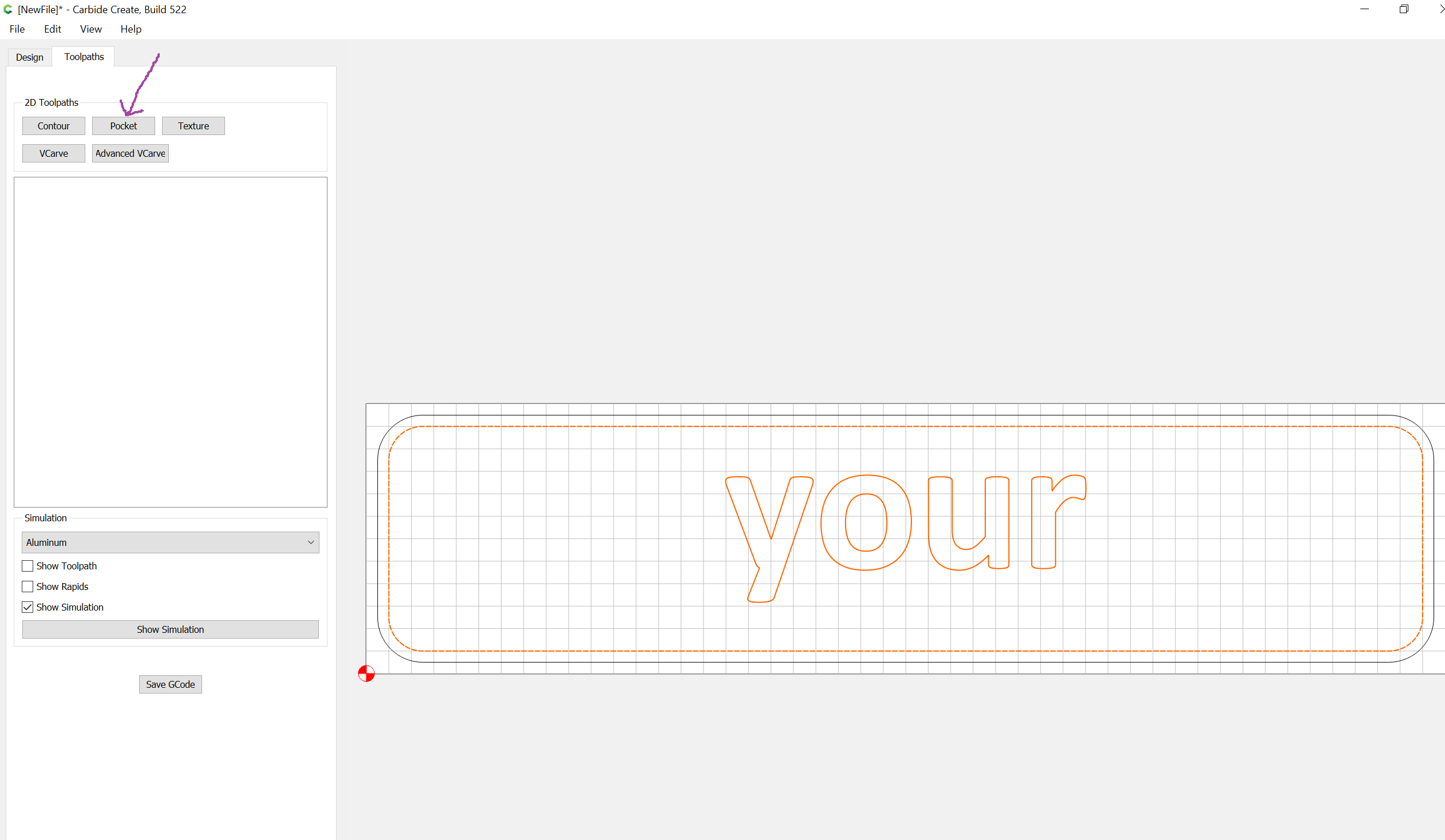
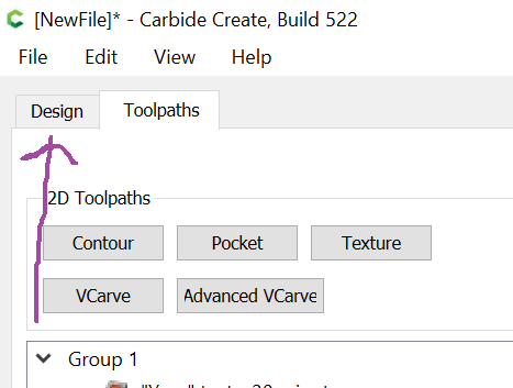
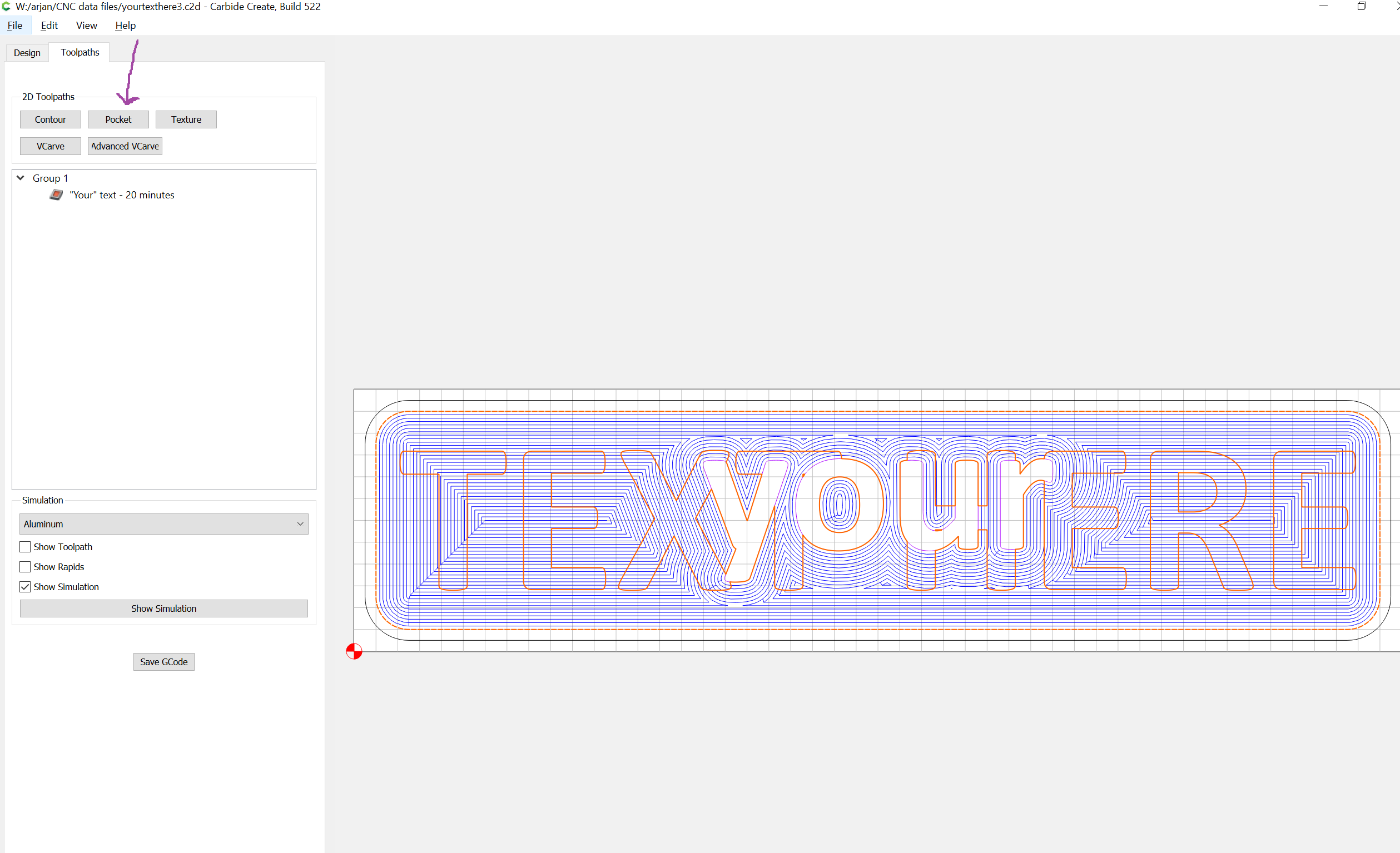
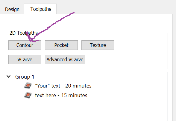
Then we go to the “Toolpaths” part of the Carbide Create application:
To let the “your” text stand out, we’re going to cut away the pocket that goes from the inside frame to the text, and we do this using the Pocket operation:
We’re going to make the pocket 0.04" (about 1mm) deep.
Make sure to select the tool you want to use as well in this screen.
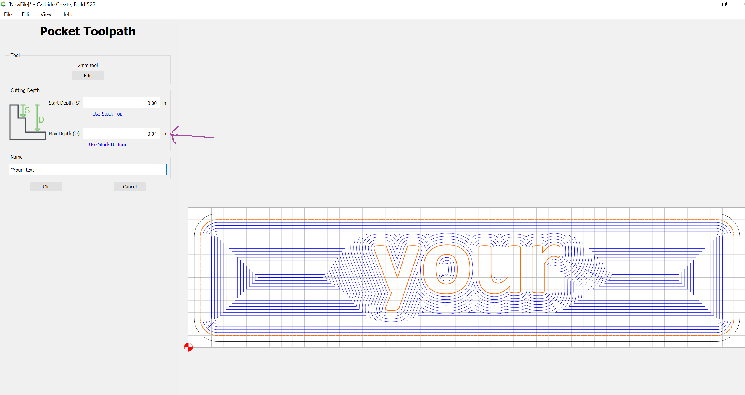
You can see in the work area that the area inside the frame will be cut, but not where the text is.
Step 6: The “text here” design
In order to add the next design element, we go back to the design screen:
We’re going to put the “text here” text on the layer we created for it, so we first need to active this layer.
Use the “L” key (or the Edit menu) to open the Layers dialog:
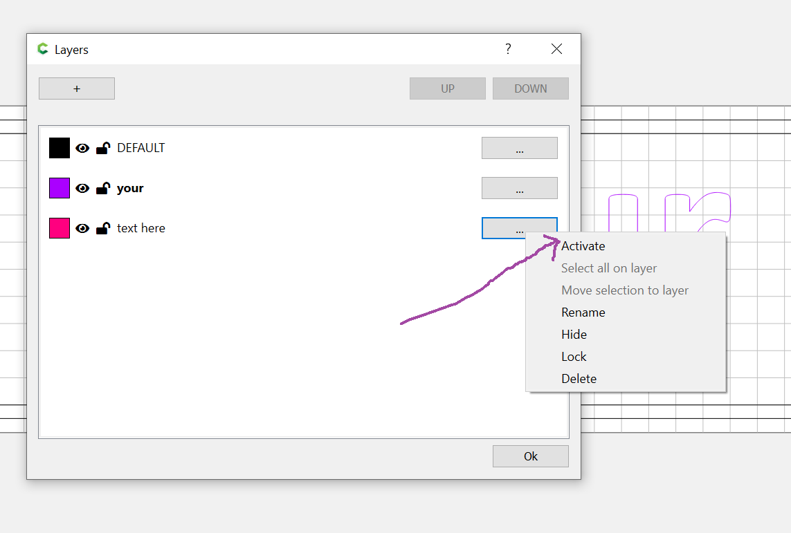
Click the 3 dots next to the “text here” layer, and select the “Activate” option. The “text here” layer turns bold to show it’s now the active layer. We’re done with layer selection to click the Ok button to close the dialog box.
Use the “T” for Text icon to add our “text here” text:
And we enter the “text here” text, while setting the size to 1.75" (I’d love to use 2.0" but in this case that will make the text exceed the size of the sign):
Notice how I used all-capitals for the text; often 2nd layer text stands out better if it’s done in all capitals
As before, don’t worry about the text on the screen not being centered…
… because you’re going to click the “Done” button first, and then use the alignment tool to center this text (same steps as before, I’m not going to repeat them)
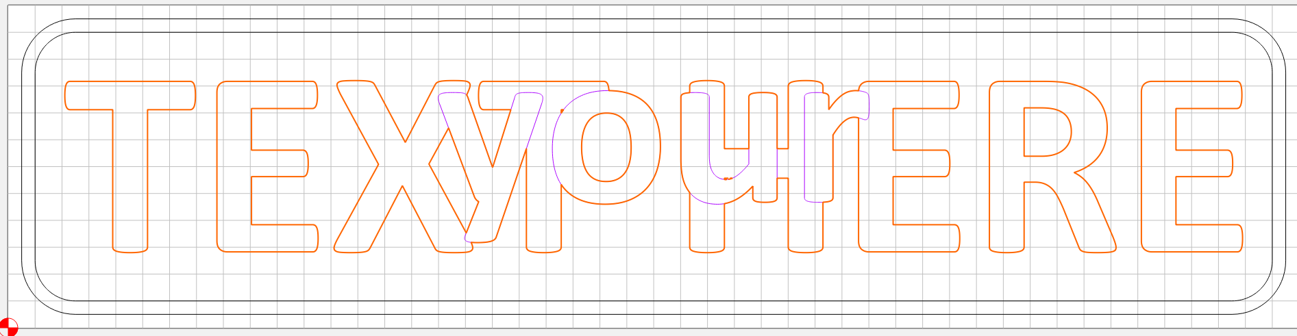
After aligning, your work area should look like this:
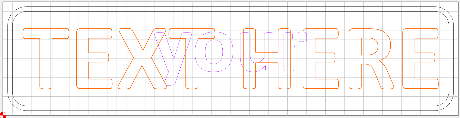
But… we’re not done yet. If we were to make a toolpath as is, and cut it out, we’d cut right through the words of “your” that we need to leave in tact, for example in the areas I colored in the screenshot below:
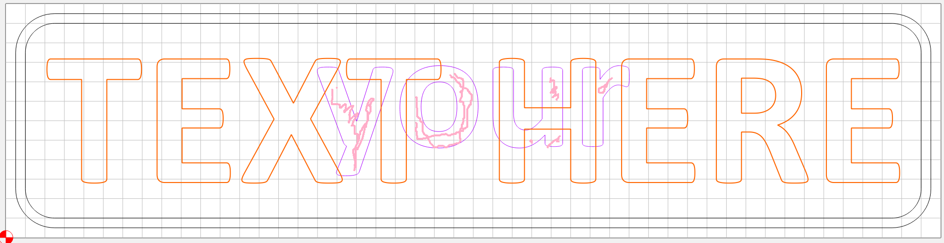
To avoid this problem, we’re going to “join” the words of “your” and “text here” into one shape.
To do this, first click on the “your” text in a convenient place so that it is the only thing that is colored orange. Then do Ctrl-C on the keyboard to create a copy of the text.
[[[ THIS STEP IS ON LONGER NEEDED AS OF VERSION 524 ]]]
What you’ll see now is a slightly offset version of “your” on top of the existing work. We will need to center this version again so that it matches the original perfectly… using the Alignment tool (you’ve done this a few times now I’m not going to repeat the detailed steps).
[[[ END STEP ]]]
The next step is to select both this new copy AND the “text here” text, you do this by holding down the Shift key while clicking anywhere on “text here”. The result should be that both “your” and “text here” are orange colored on the screen.
Now that both text elements are selected, we’re going to turn this into a “joint element” by using the “Boolean Union” operation:
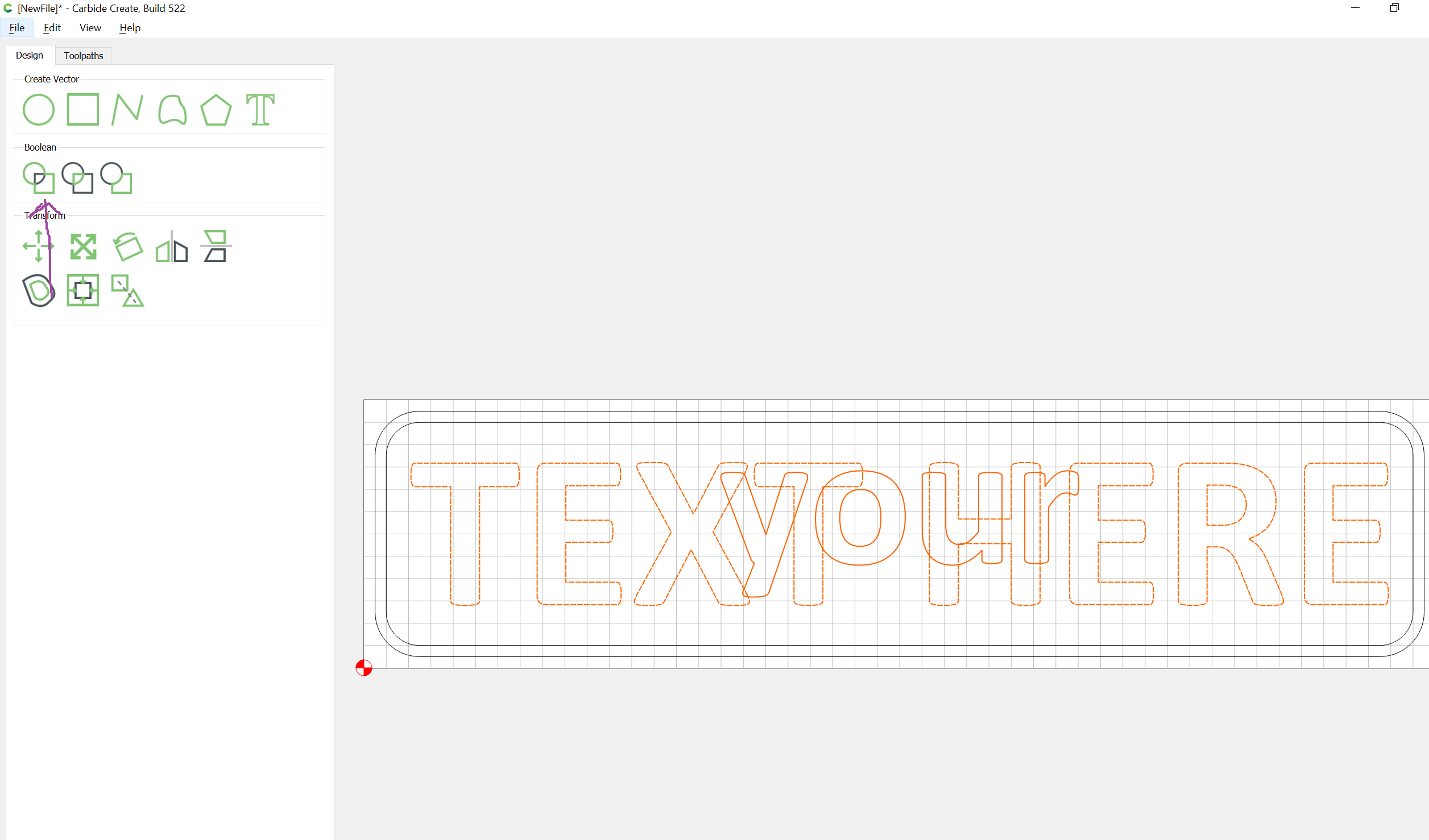
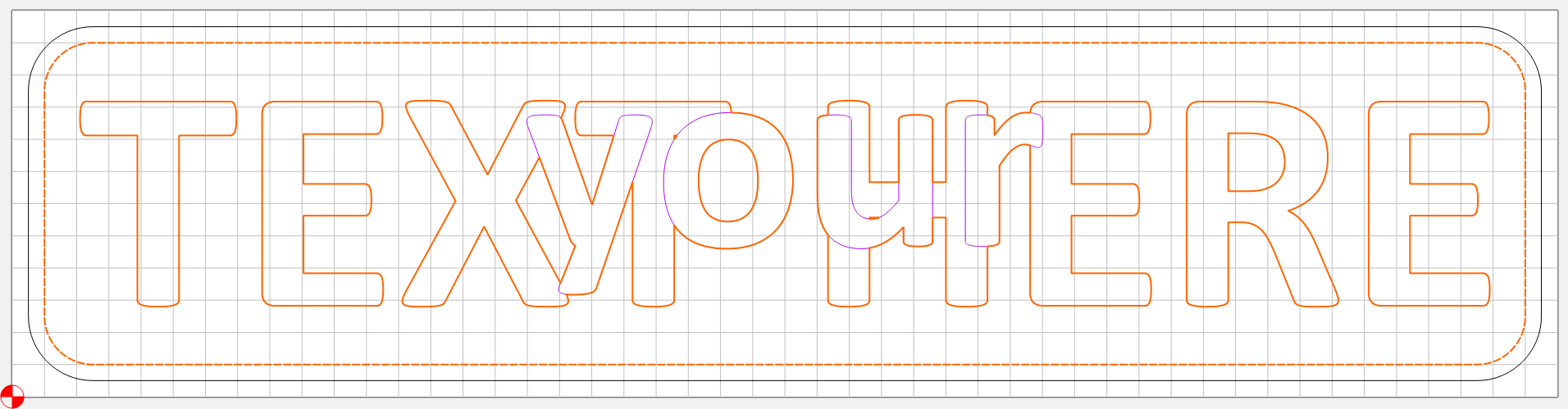
The difference is a little subtle, but the work area should now look like this:
The big difference is in the letters of the word “your”… there is no longer any lines crossing through these letters!
It’s extremely convenient to group all these vectors together, using the “group” tool:
Step 7: Toolpath for the “text here” layer
To make the toolpath for the “text here” layer, leave this new joined “text here” selected, and hold down the shift key and click on the inside frame rectangle to add this to the selection:
Now we go to the toolpath screen again:
And click the “Pocket” button to add a new pocket operation:
The second layer of the cut needs to start where we left off before, so at 0.04", and we’re going to cut to a depth of 0.08" (roughly 1mm to 2mm):
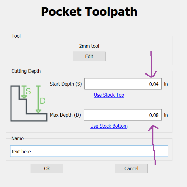
Give the toolpath a useful name and click “ok”
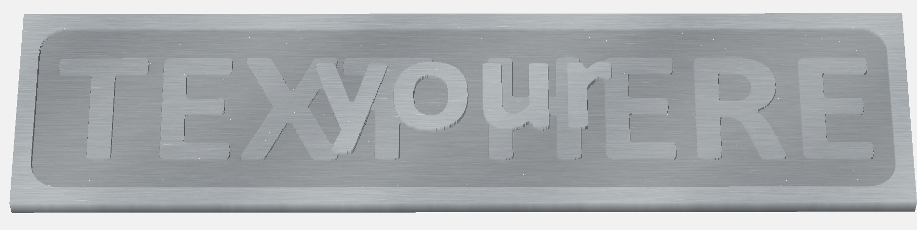
We’re almost done! If you look at the simulation you can already see the 2 layers of text come out:
Step 8: Cutting out the outside
The last step is to cut the rounded outside rectangle out so that the sign becomes a standalone piece.
While we stay in the toolpath screen, and need to select the outside rectangle. This can be a bit tricky since Carbide Create sometimes wants to select the inner rectangle instead; if it’s doesn’t “take” on the first try, try clicking somewhere in the middle of the upper “long stretch” of this outside frame, until it turns orange like this:
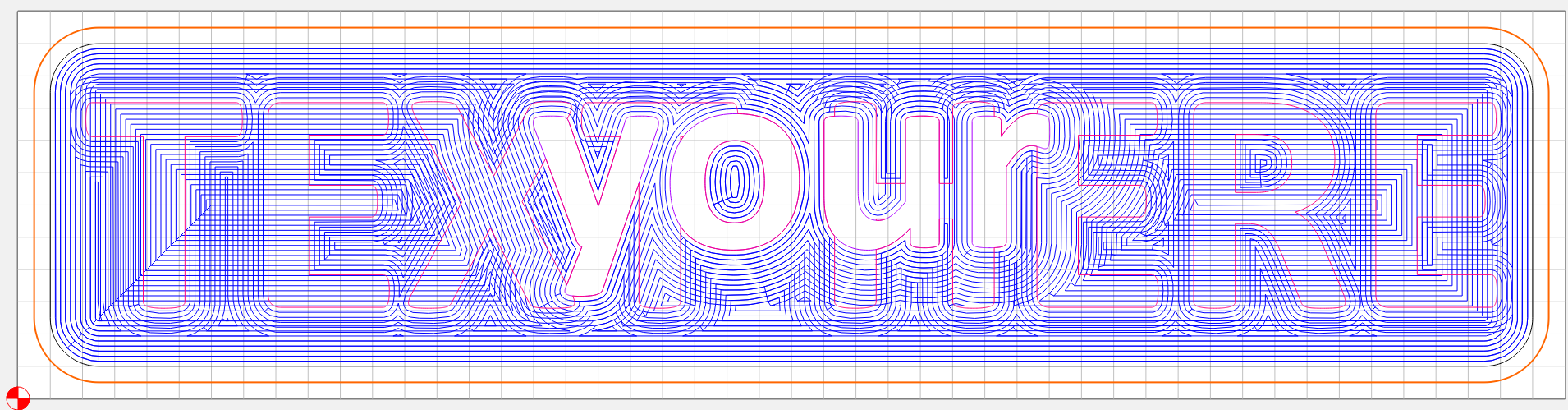
To do this cutout, we’re going to use a “Contour” operation:
This cutout we want to be to the full depth of the work, so use the
“Use stock bottom” selection to set the depth to 0.25"
It’s also important to make sure we cut on the Outside of the selection, to cut the work out:
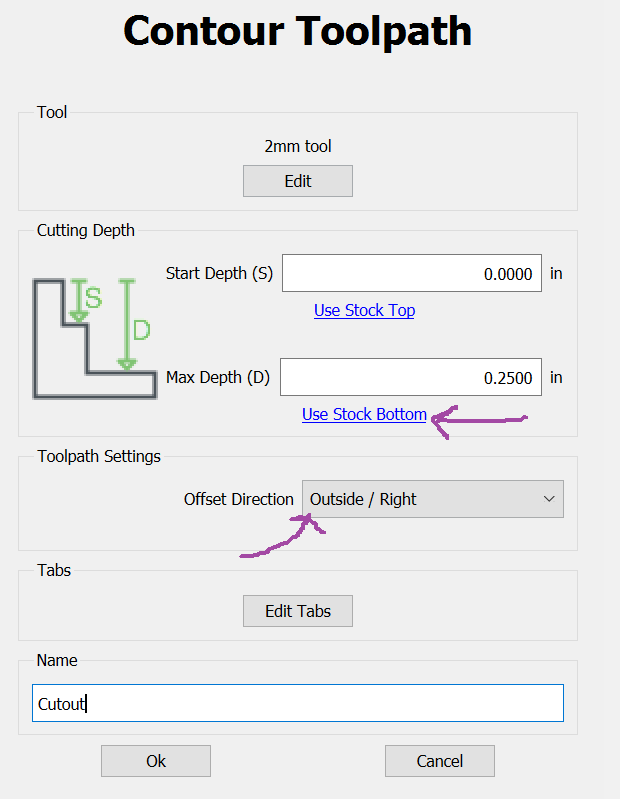
Click the Ok button…
… and we’re done! The design is ready to export to Gcode and for Carbide Motion to send it to your Shapeoko CNC.
The preview should now look like this:
If you want to compare your work with my file, my file is here:
yourtexthere3.c2d (1.2 MB)
I’ll be cutting this out shortly and I’ll edit this post to add pictures of the result.

 )
)
