tink07
(Keith Tinkler : Pro Photographer : Sales Person : Retired)
1
I have just ordered a HDZ & mount for my new 1.5Kw water cooled spindle and VFD…
I am looking for any ideas on:
Piping the cooling tubes
Cabling for spindle
Where to put the VFD…do i need it close by??
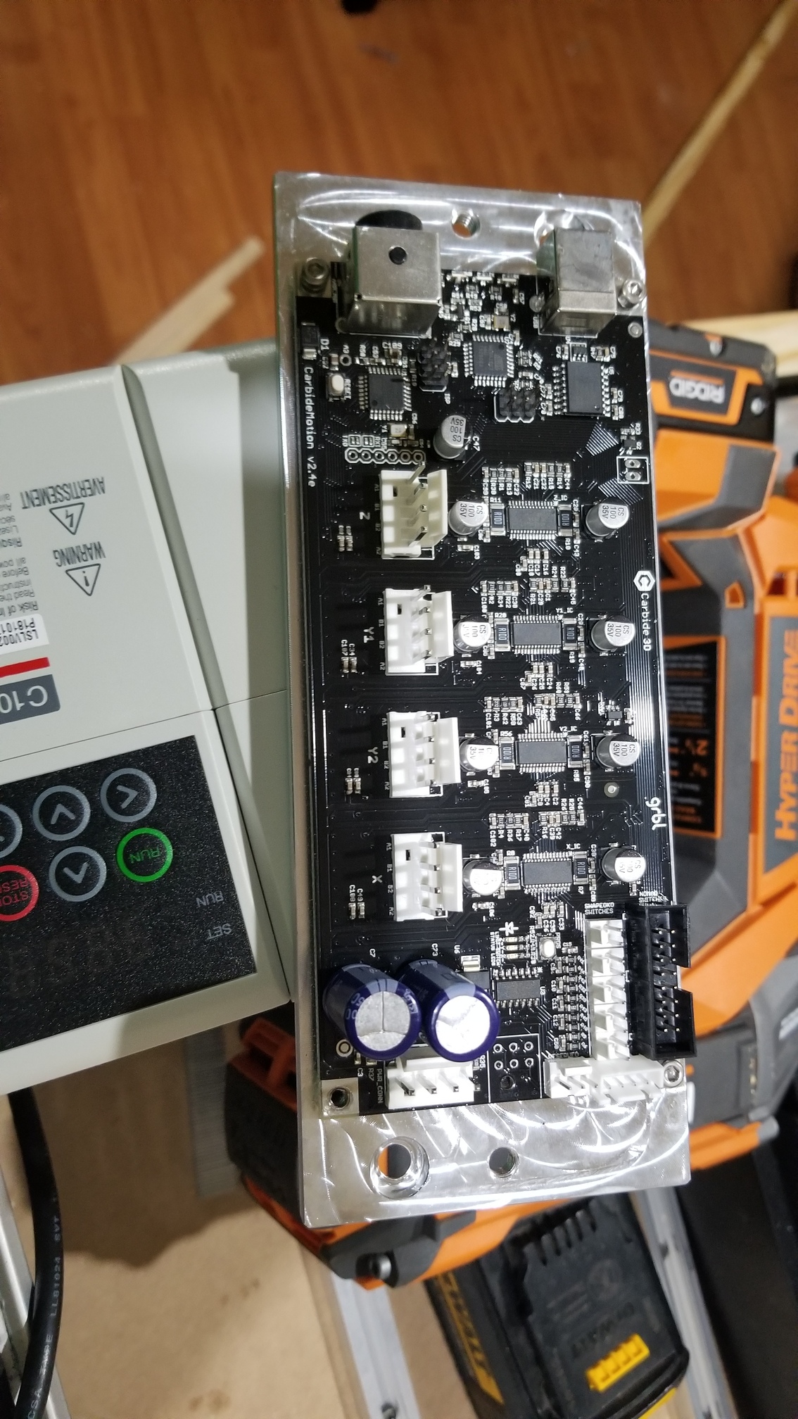
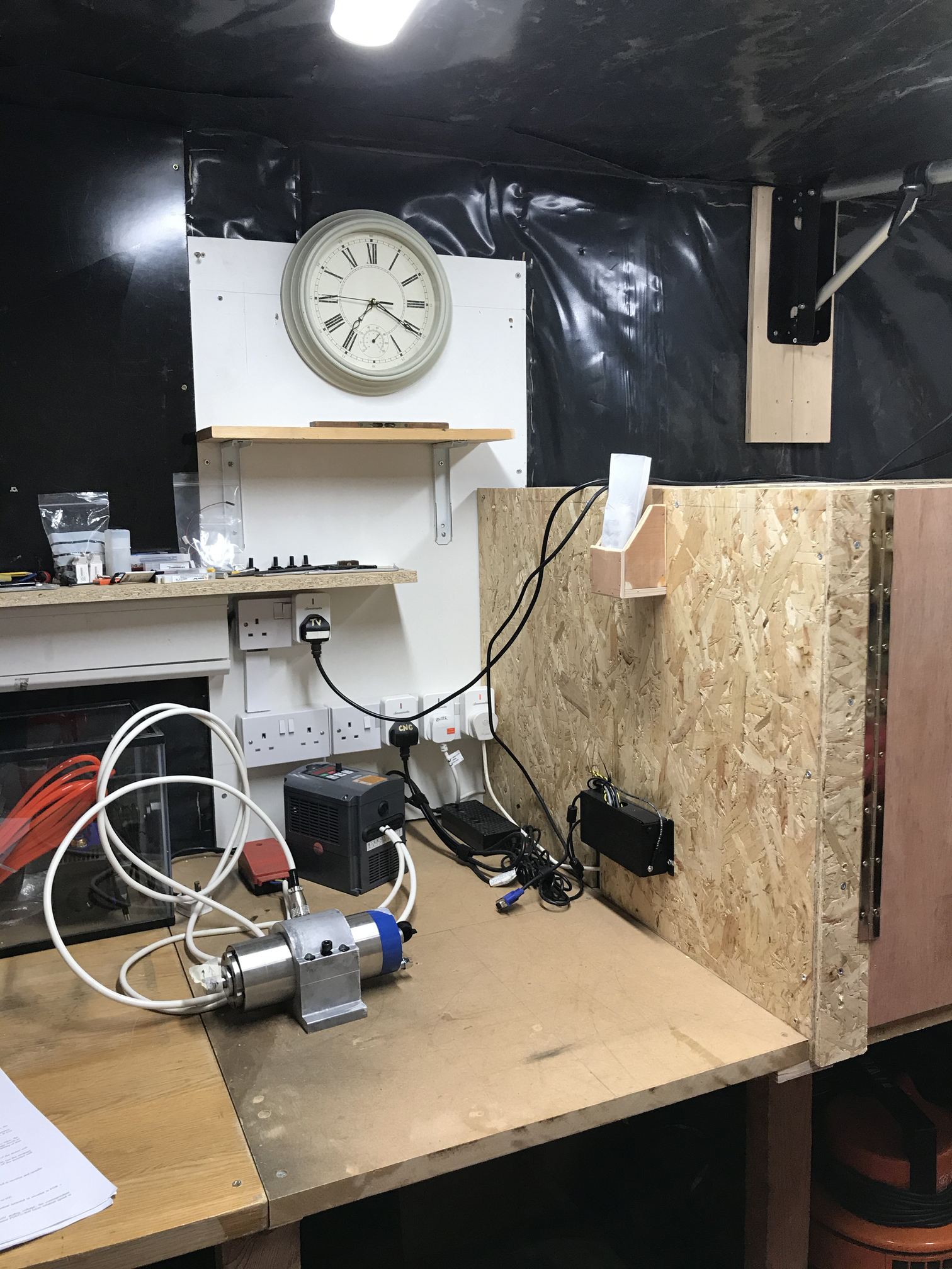
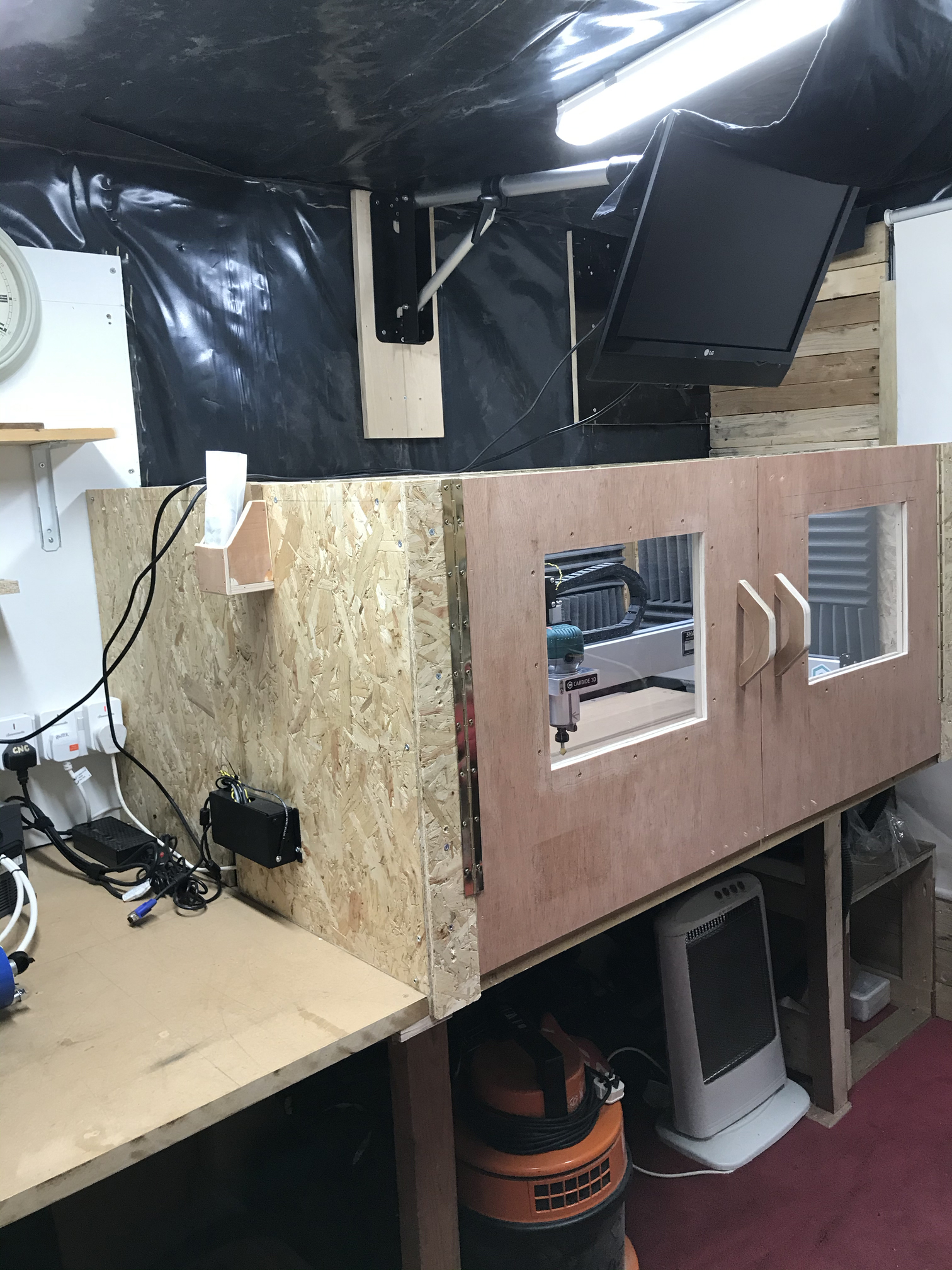
I have attached a couple of images of my set that may help
Thank you in advance!
Everything you could possibly want to know about doing it right is in that great thread:
The VFD “just” needs to be somewhere where it will having a little breathing room, it does not have to be very close (you won’t interact with it much once installed anyway)
My setup does not have drag chains, so I just hang the spindle cable and cooling tubes from the ceiling of my enclosure. For a Shapeoko3 it works, for an XL or XXL the drag chain approach is much better.
I’d add (unless it’s in the thread and I missed it);
You’ll ideally want a proper metal or cement (brick concrete etc.) mounting point for the VFD, not wood, when they fail they can do so with quite a lot of energy. They’re unlikely to start a fire, but electrical regs are there for the unlikely, especially if the VFD is already full of flammable wood dust from being operated in a workshop.
I’d say that an E-stop and No Volt Release are also not really optional by the time you have three phase power, several horsepower of spindle and possibly the VFD controlled by software to start the cutter on it’s own. Fumbling for the little stop button on the VFD or with the mouse to try to stop the machine in Carbide Create just isn’t a substitute for the “STOP!!!” button when you need it. That’s just my opinion.
I would also say that a Residual Current (in the US they’re called Ground Fault) breaker upstream of the VFD is also a non-negotiable, again see the thread linked in 2, these aren’t the highest German quality and faults are relatively likely.
Screened cable and a power filter are also pretty essential, the screened cable is covered in the thread Julien linked. you’ll need four cores for three phases and earth from the VFD to the motor, measure up what you think you’ll need and add 6 feet Good screened cable will have a reasonably heavy braid capable and a foil screen. The power filter goes on the input to the VFD to stop the input rectifier noise upsetting your Shapeoko, PC or other electronics.
There’s loads of options on the water cooling circuit, bear in mind you won’t really be using a lot of spindle power on a Shapeoko due to machine constraints so I’d start with a suitable water container you can get the supplied (horrid) fountain pump in until you decide whether you need active cooling. Remember to use a corrosion and fungus inhibitor such as anti-freeze, preferably use de-ionized water.
I decided to just add on extra drag chain for my spindle power and plumbing and just leave the Shapeoko motor and signal wiring on it’s own in the original drag chain, this was to reduce the interference risk of the motor power cable to the signal cables, just a few inches buys a huge drop off in EMI .
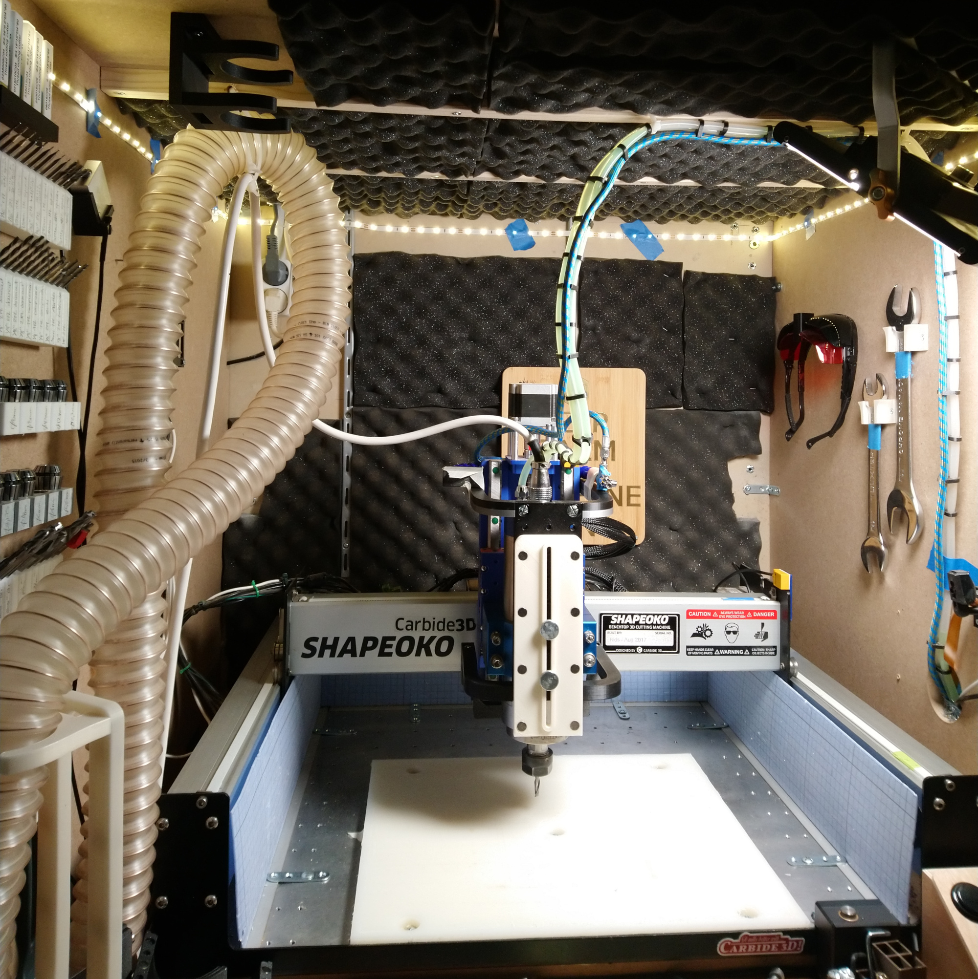
Some pics of my work in progress below;
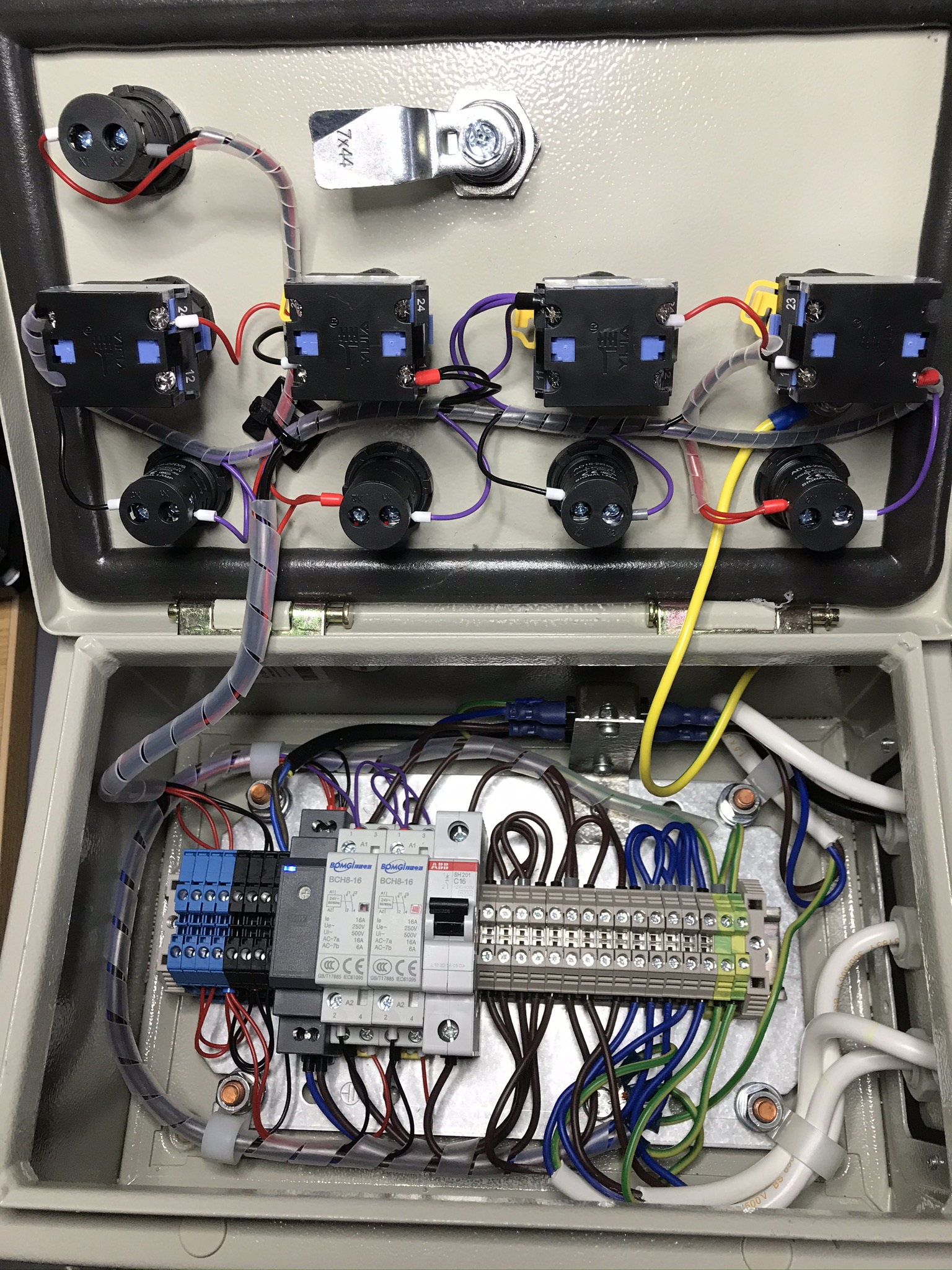
Electrical switchgear box with 24V contactors to give me No Volt Release, E-Stop and separate power to the Shapeoko and the Spindle / Coolant Pumps etc. The VFD power filter is hiding behind the bright yellow / green earth cable running from the box to the front panel.
Where I should not have put the VFD, on the wood of the stand, it’s going inside a switchgear metal enclosure as soon as I figure out an RS485 remote panel so I can see the RPM etc. when it’s locked away, for now it and it’s irritatingly noisy always on fan are in view near the front of the machine but out of the path of most of the dust that escapes the extractor.
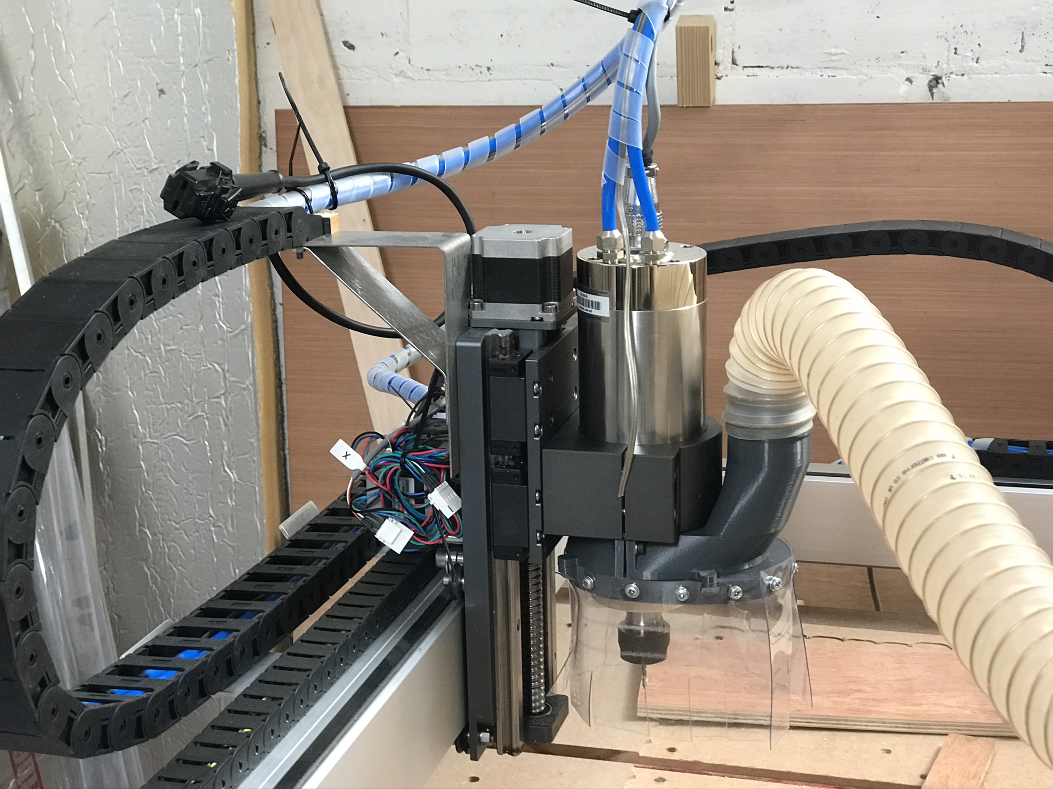
Here’s the additional drag chain, note the spiral wrap binding the hoses and motor power cable between the drag chain runs and into the ends of the drag chain. The spiral wrap bound group is tied into place at each cable chain entry / exit to reduce wear points on the cable and hoses. I just bent up some aluminium brackets and drilled and tapped the back of the X rail (sacrelige, I know)
Wiring and hoses to the top of the motor, make sure they don’t kink or flex too much as the Z goes up and down, I’m going to sort a better bracket soon, honest…
I recon the side of the enclosure is a great place. I once put the VFD at the back under my bench. Boy was that a bad idea…
Also I can’t help but notice the case spindle mount you have there. I’m not trying to sell you on the HD spindle mount but the reason we made them is because the cast ones are junk. I have 3/4 in my scrap bin. They have rough edges, are not straight or flat and no mounting holes.
It was one of these from eBay, they’re for making your car headlights look like they’re LED.
If anyone wants the fusion360 files for the mounting bracket let me know.
2 Likes
tink07
(Keith Tinkler : Pro Photographer : Sales Person : Retired)
7
Hi LiamN, thank you for that really interesting and some great markers which I will take on board… Thank you.
I wll buy the “eye of sauron” i checked the link and it’s ended… do you know where else to get one… funny being an ex photographer … yes I should have had one.
Is that Newcombe in the south??
tink07
(Keith Tinkler : Pro Photographer : Sales Person : Retired)
8
Hi goldbeech… Welcome to the community I’m a newbie and I find this site is very good for all the help
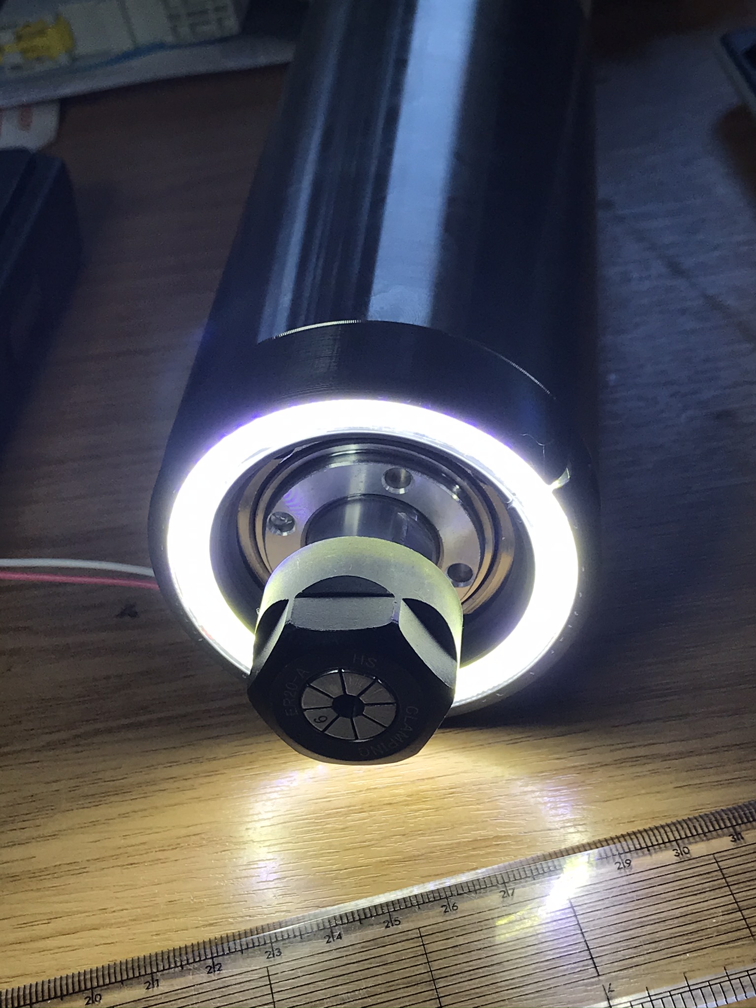
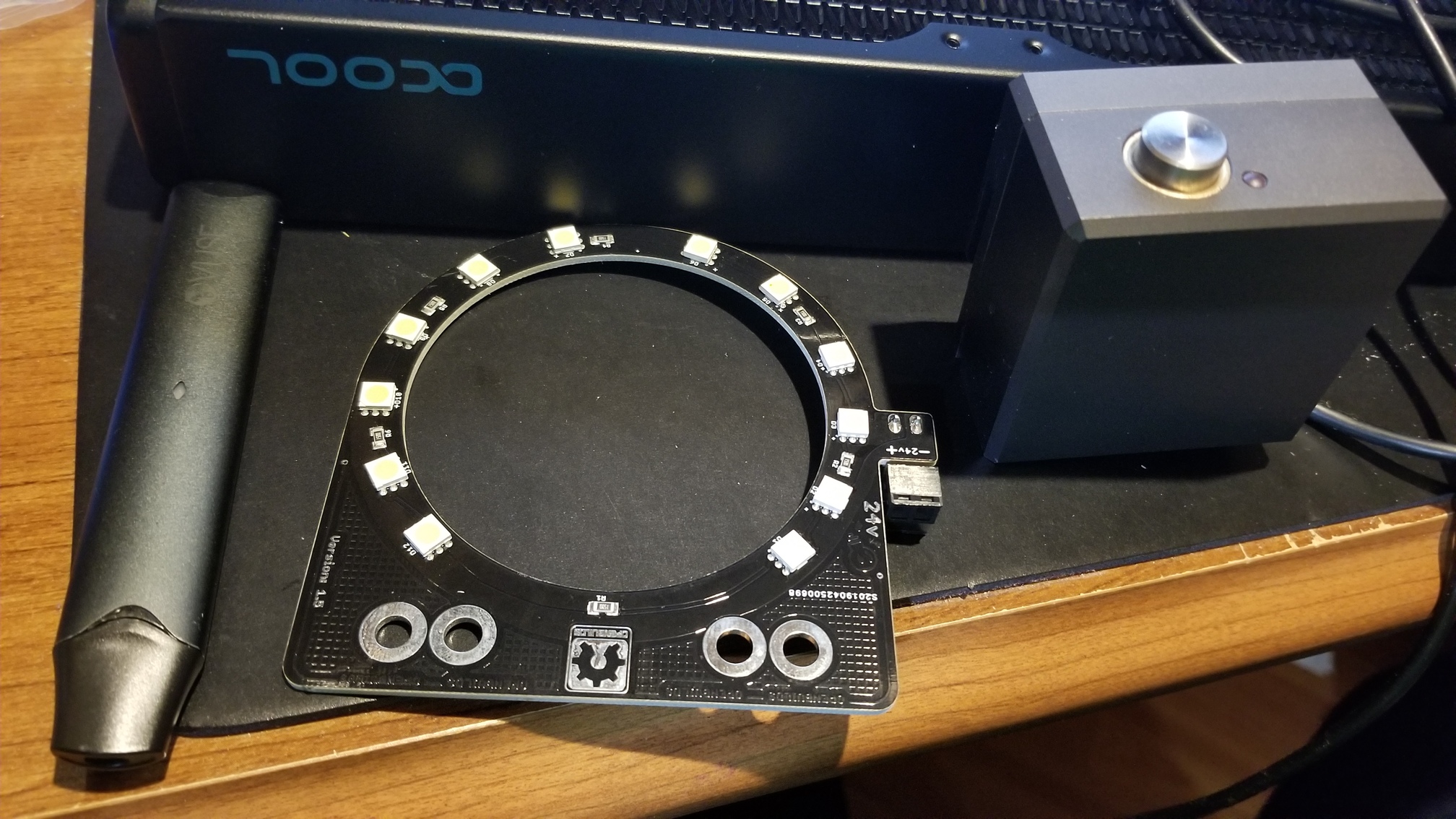
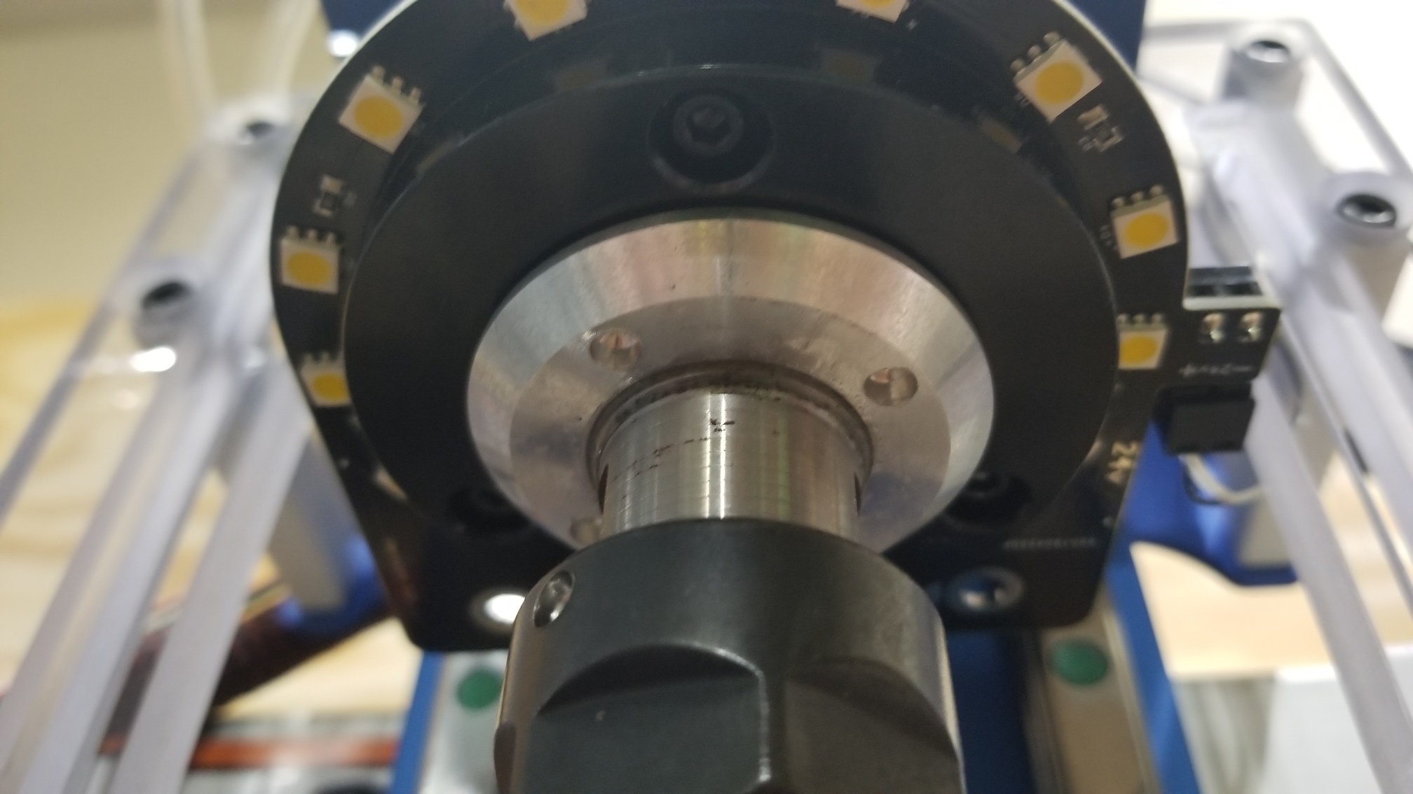
Yep, I’m in Croydon, and yes, a ring flash was exactly what I was thinking with the LED ring on the spindle
If you search eBay for “angel eyes” that seems to be what these things are called, these look like very similar units to the one I got, I bought the 70mm as it was a good size to sit inside any 80mm clamp on dust boot but wide enough to clear the spindle rotating parts.
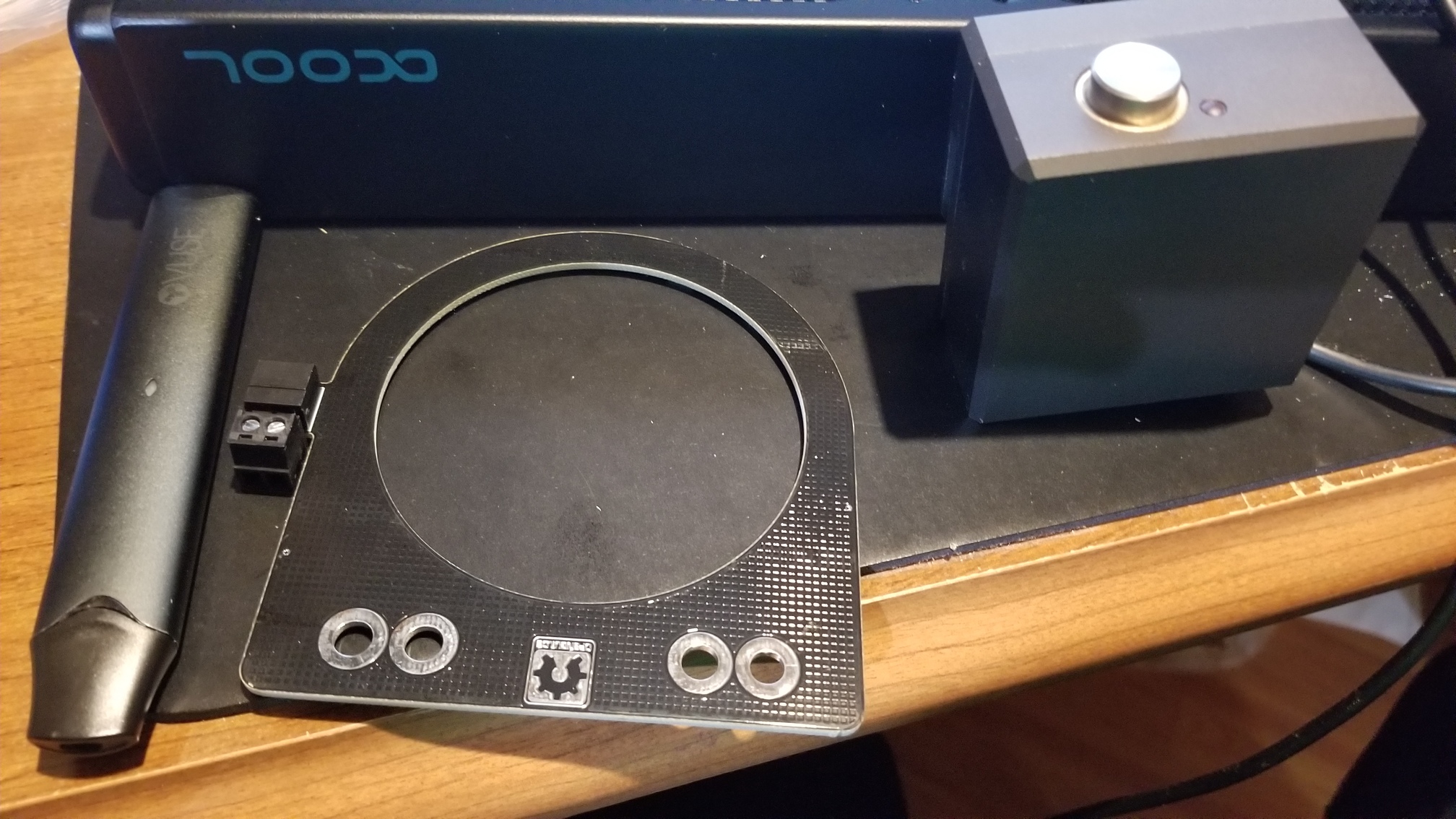
Here’s the file, the mount for the LED ring is split into two parts to make it easy to print without supports, it also needs one M3 countersunk head bolt to work as the clamp.
The model is pretty specific to my spindle and the LED itself but those are both in the CAD so they should be easy enough to change if your spindle or LED has different dimensions.
Let me know if you have troubles with my CAD
Is there a files repo for Shapeoko stuff anywhere (or is that Thingiverse) ?
edit - probably worth adding that I have not yet figured out where to put the little constant current driver that comes on the leads about 10cm away from the light ring yet, I’m thinking of cutting and extending those leads.
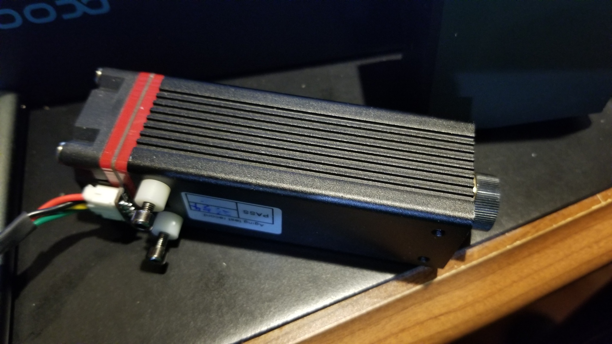
@Julien I would really appreciate it if you can help me with a bracket to attach this 20Watt laser to my HDZ with the Suckit boot. I got it connected directly to my board and was tested working as it should. I soldered a 4pin Molex to the board, next to the Bitsetter/Touch Probe connector, to make things look good. you can see the connector on 2nd picture.
I see a white cover that shows in your picture, what is that? or, what is it for?
The white thing in my pic above is part of the (over-designed) 3D-printed frame I added around my HDZ to have a Z-independent mounting structure for various things (dust collection, laser, air jet), all the details are in that thread.
You need to decide if you’d rather
attach the laser on the spindle, to have variable-Z lasering capability, which I discovered is interesting at times. I did just that recently.
or have it Z-independent…and then reusing those Suckit arms is the way to go in your case. I’ll be happy to help with a little Fusion360 prototyping if I can.
 Good screened cable will have a reasonably heavy braid capable and a foil screen. The power filter goes on the input to the VFD to stop the input rectifier noise upsetting your Shapeoko, PC or other electronics.