have been asked to help with an oar holder project. Here is the part that I would like to use CC to design and then cutout. Using this to learn…much more complex than what i have previously done. Not totally sure how to start. Maybe start with Create Curve and then the note editor??? Just looking for basic direction. tx.
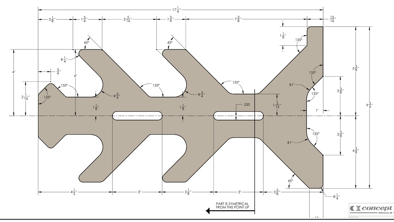
Can you get a version of the diagram with only the holder - no text, no dimensions?
If so, you could try having CC trace the object, then resize to the actual length. If you can, a lossless format like PNG would work better.
I would take photo (jpg) and import as a background, then start using circles for the lower curves of the arm/body section. Then you can set up some squares with radius corners for the top of the body. You can lay shapes over other ones until you have all the outline complete. Then you can cut vectors to get rid of the interior lines that cross each other and leave the outline OR, use the Boolean function to remove vectors not wanted.
This is much the same as:
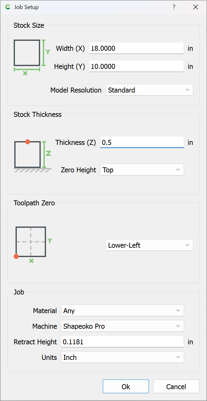
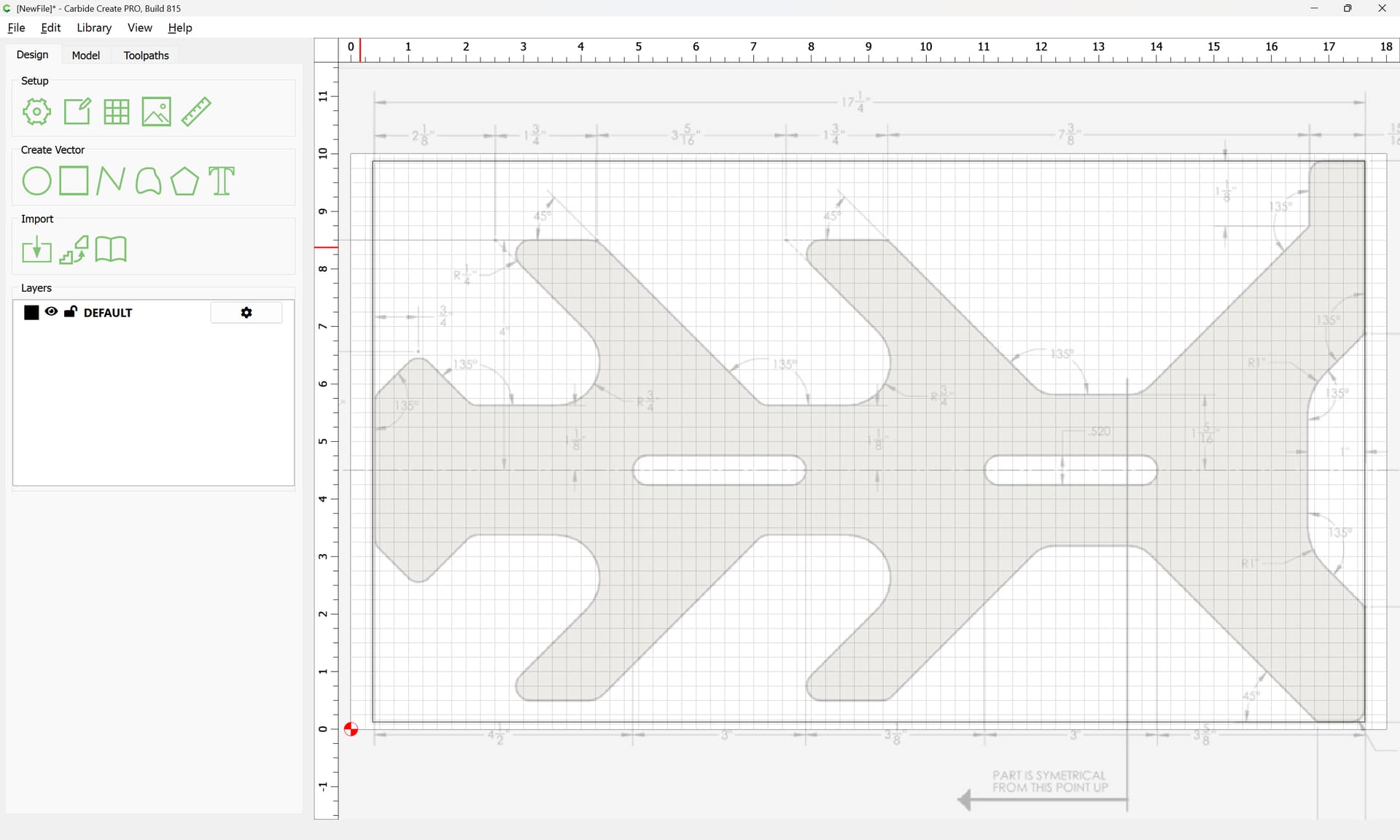
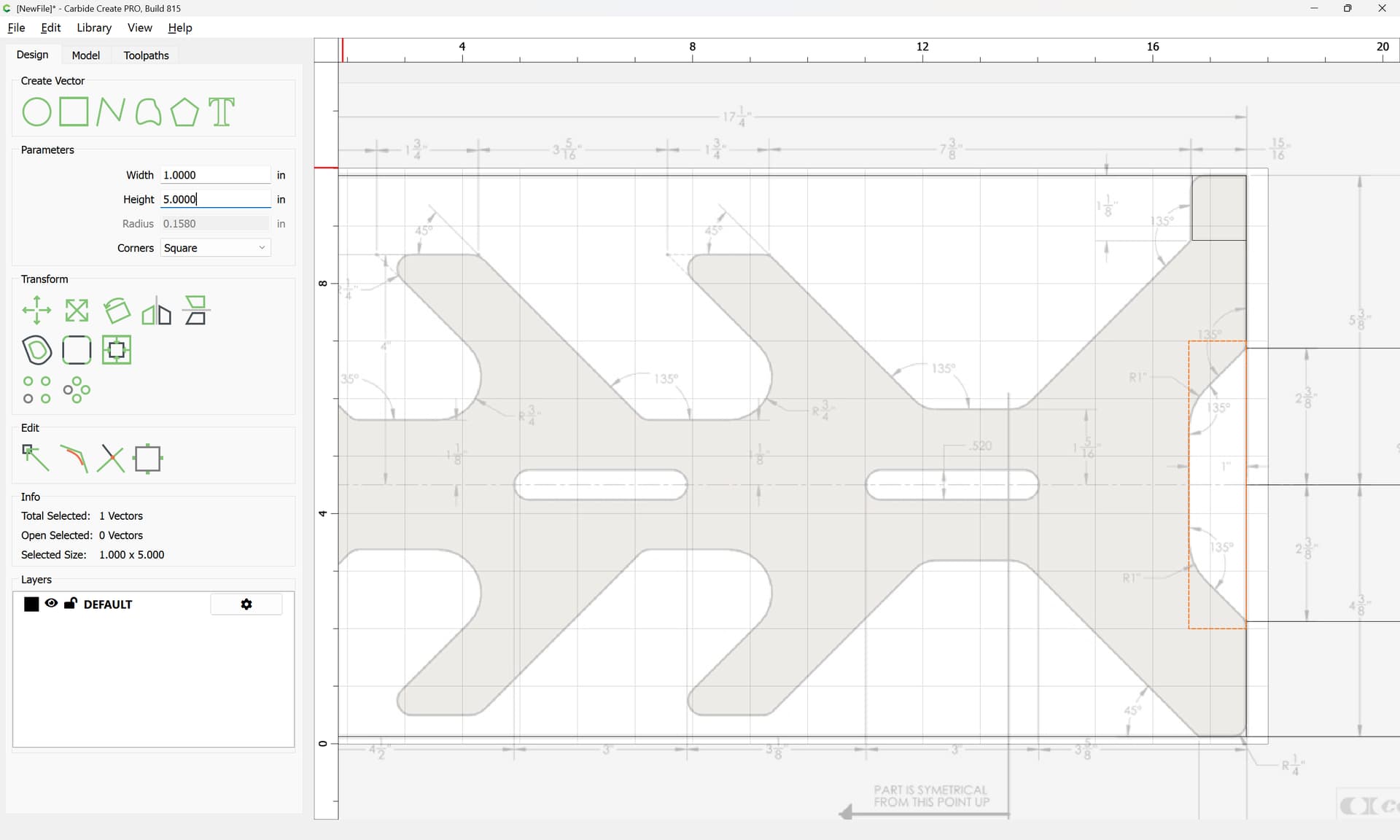
Start by making a project of the appropriate size:
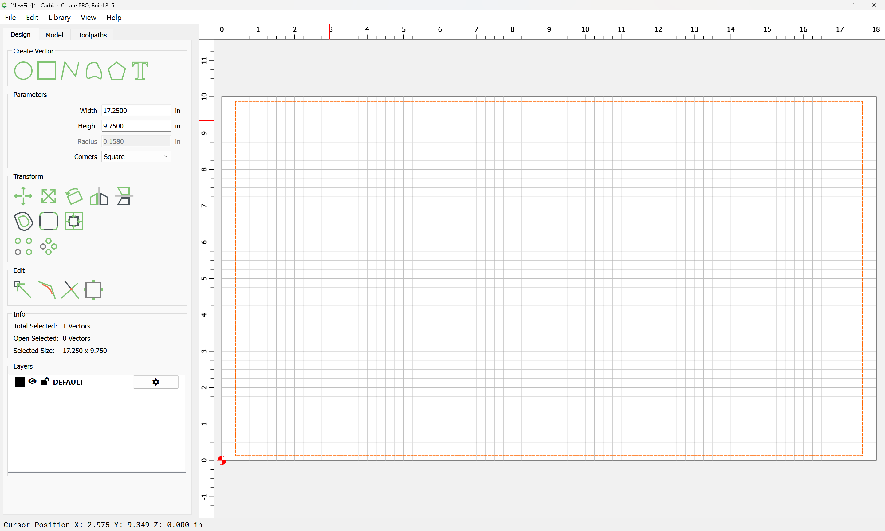
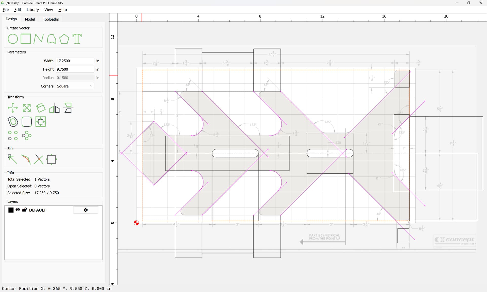
Then draw a rectangle of the overall dimensions (for reference)
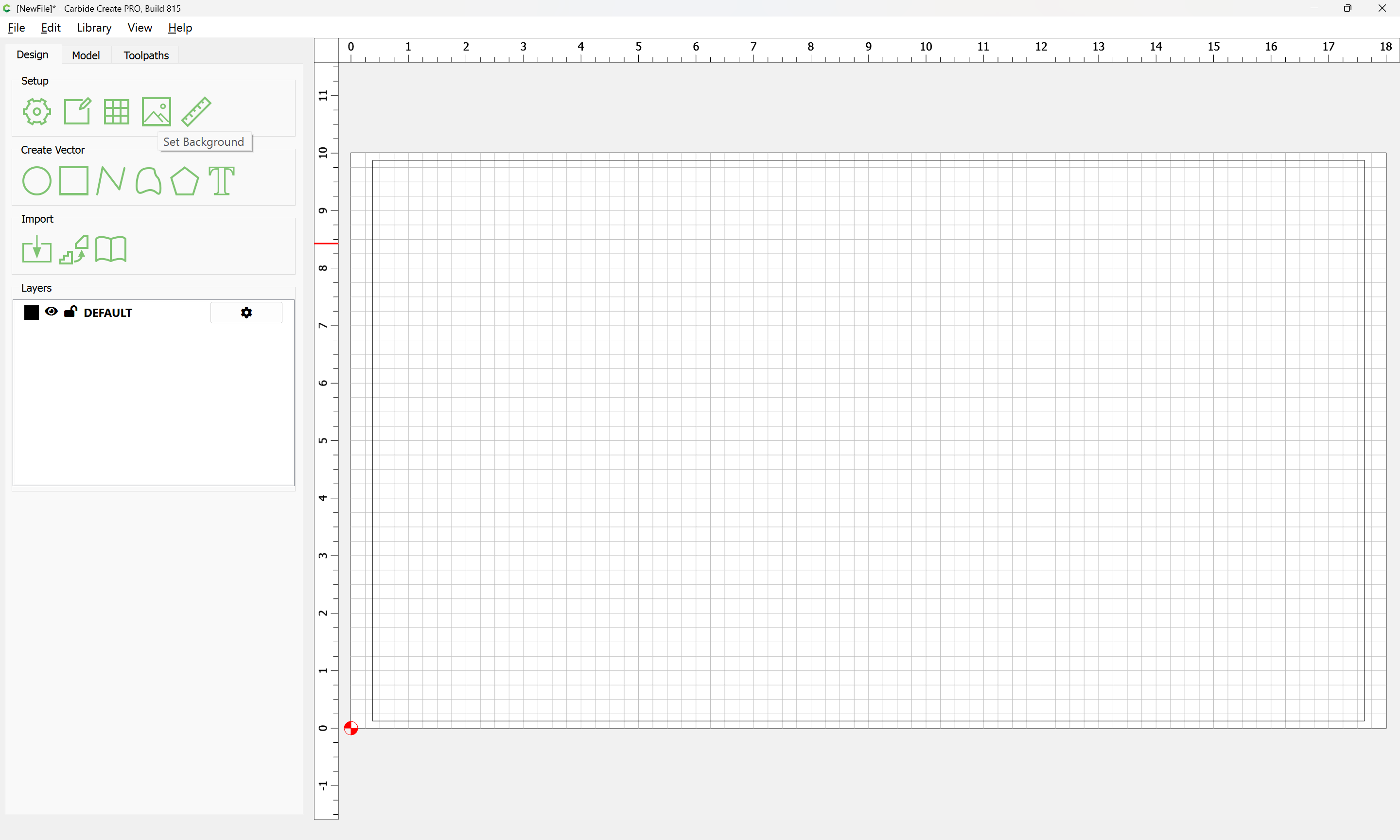
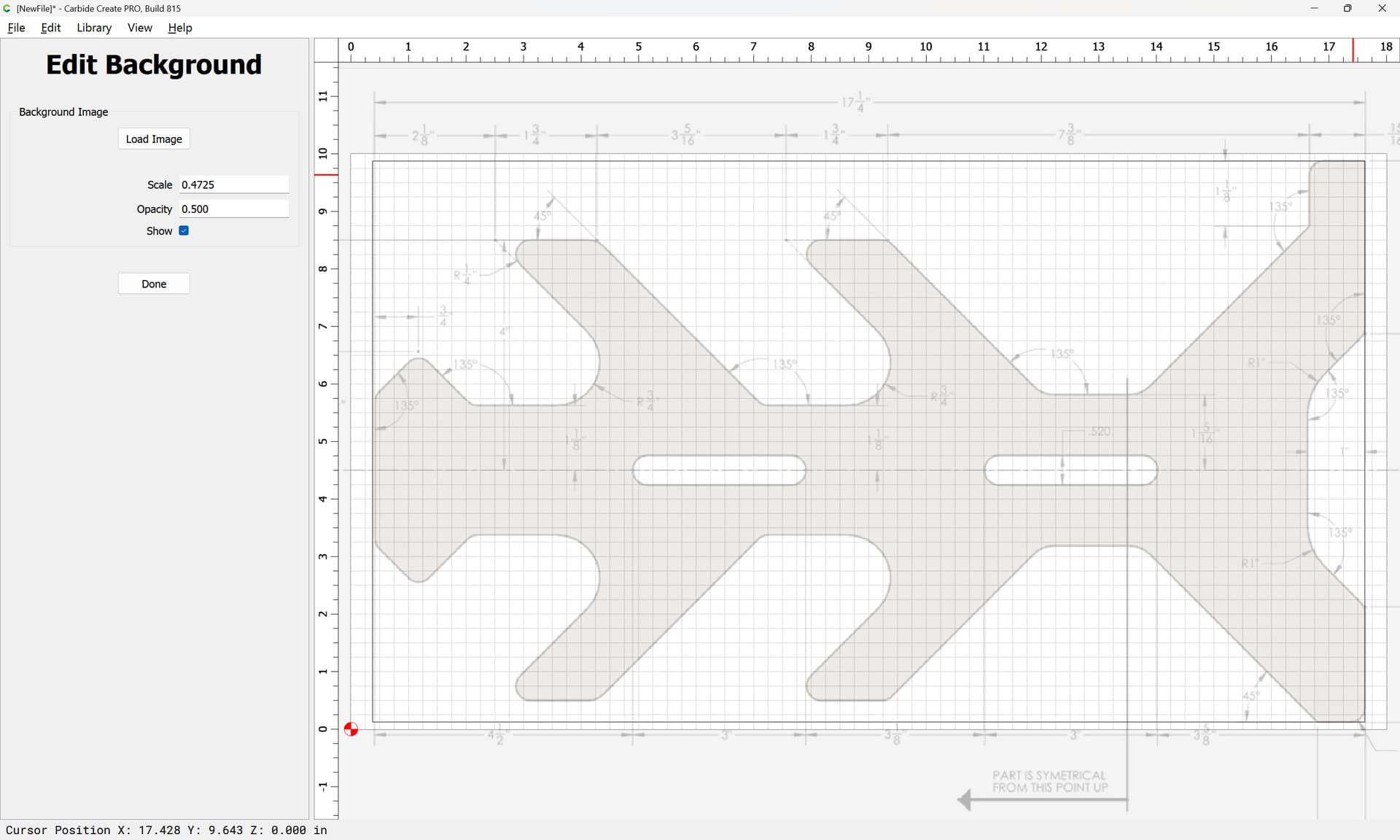
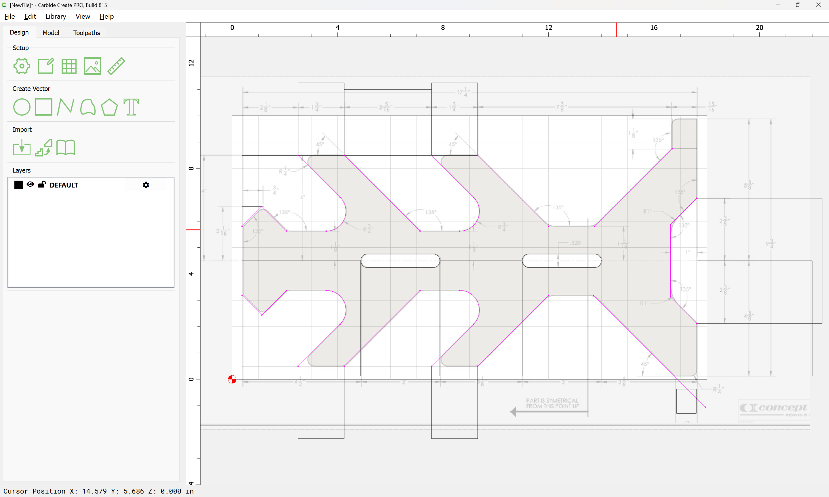
Then import the pixel image as a background reference:
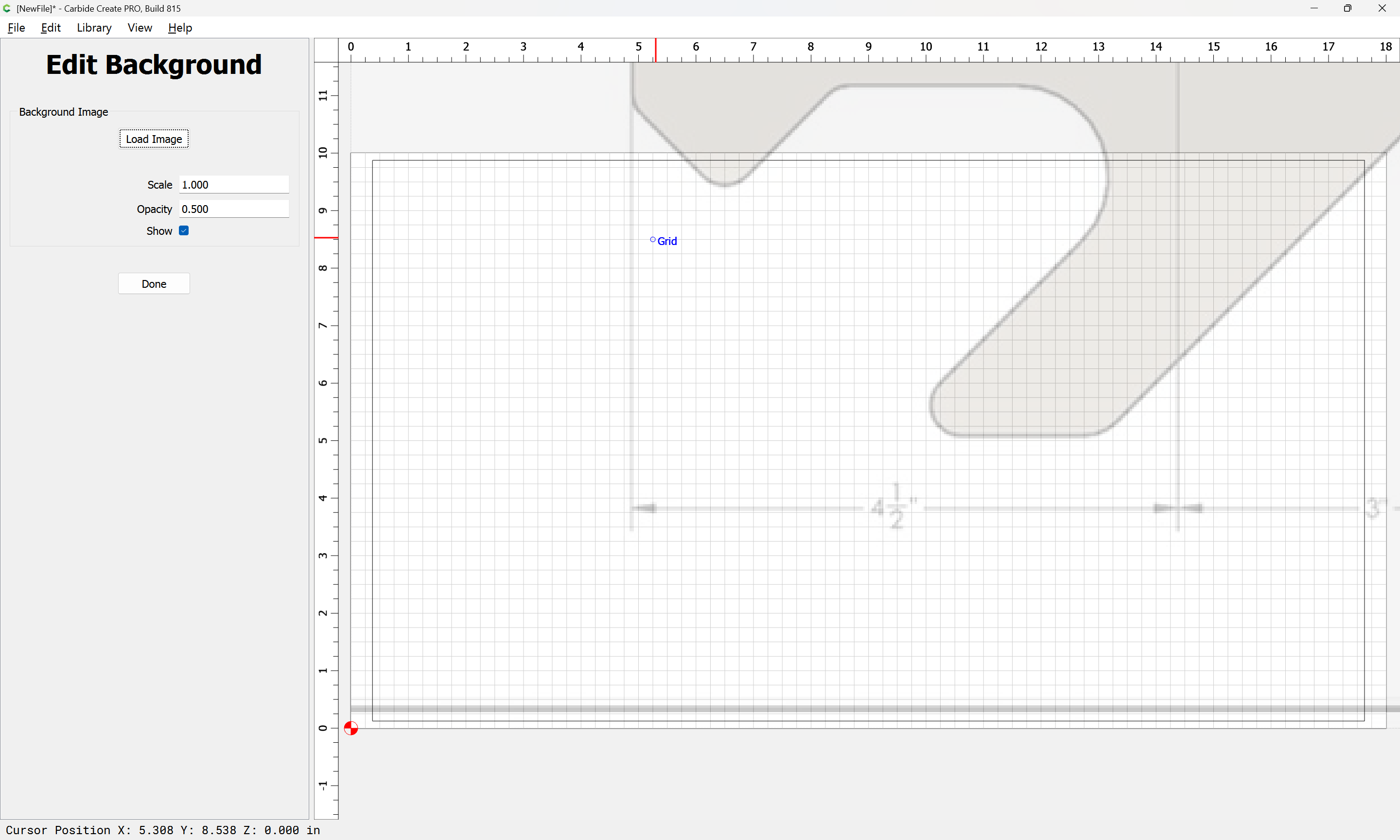
adjusting sizing and placement until things line up:
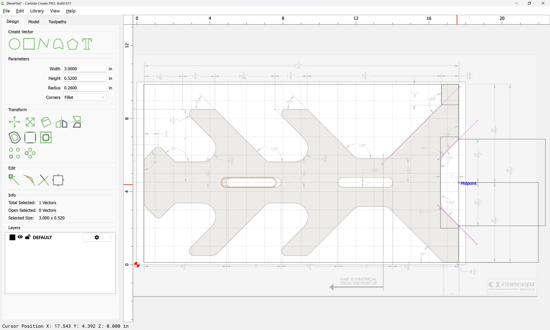
Then draw in elements…
1 Like
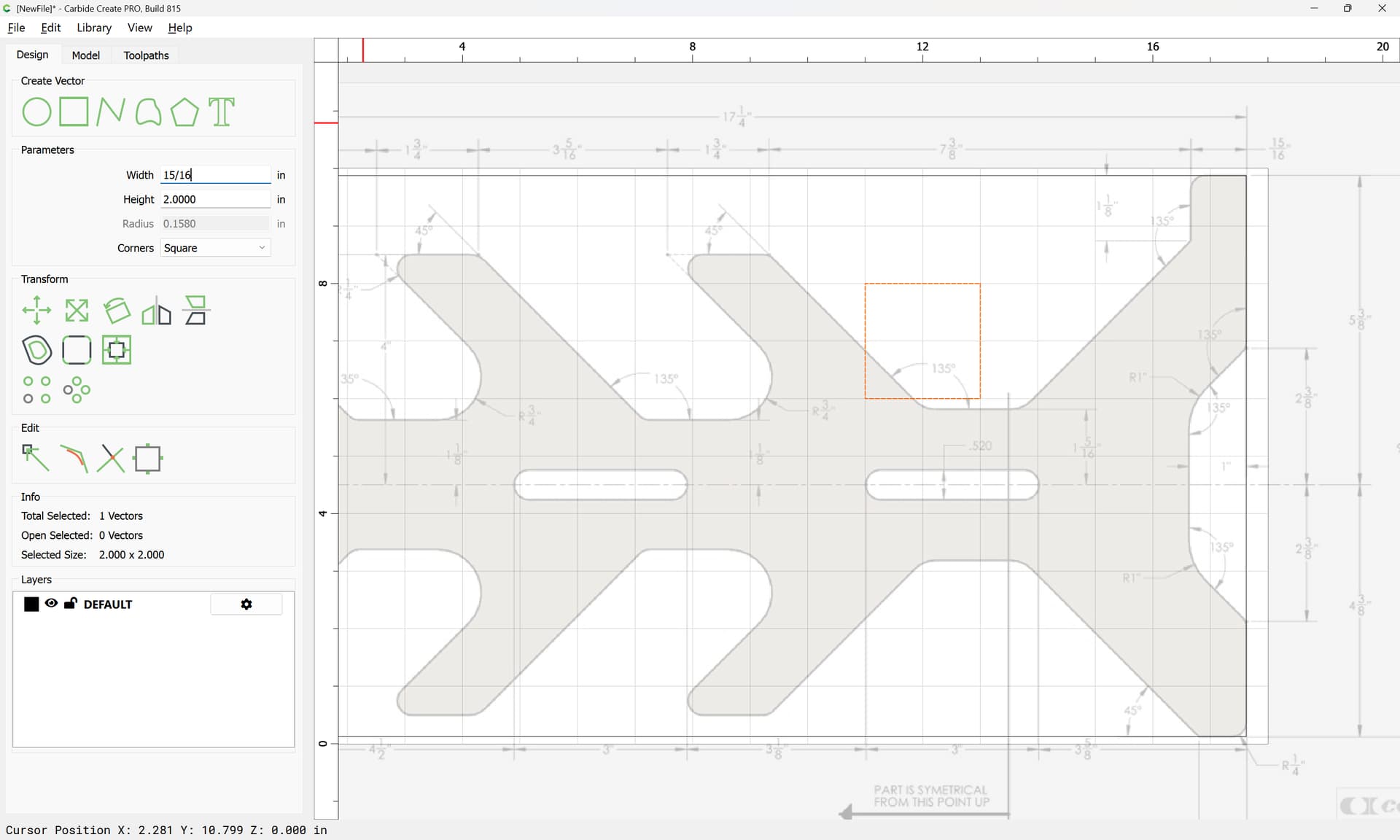
and position them:
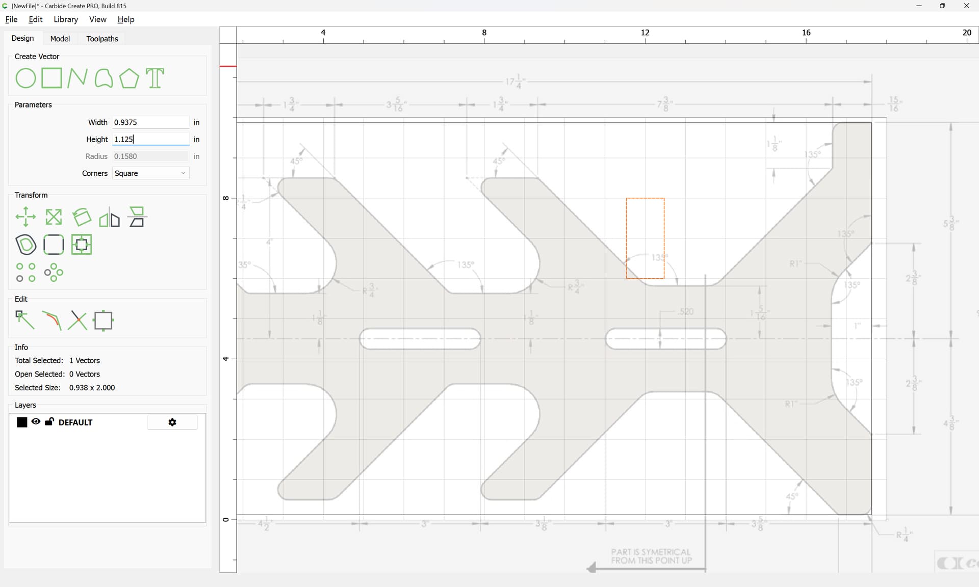
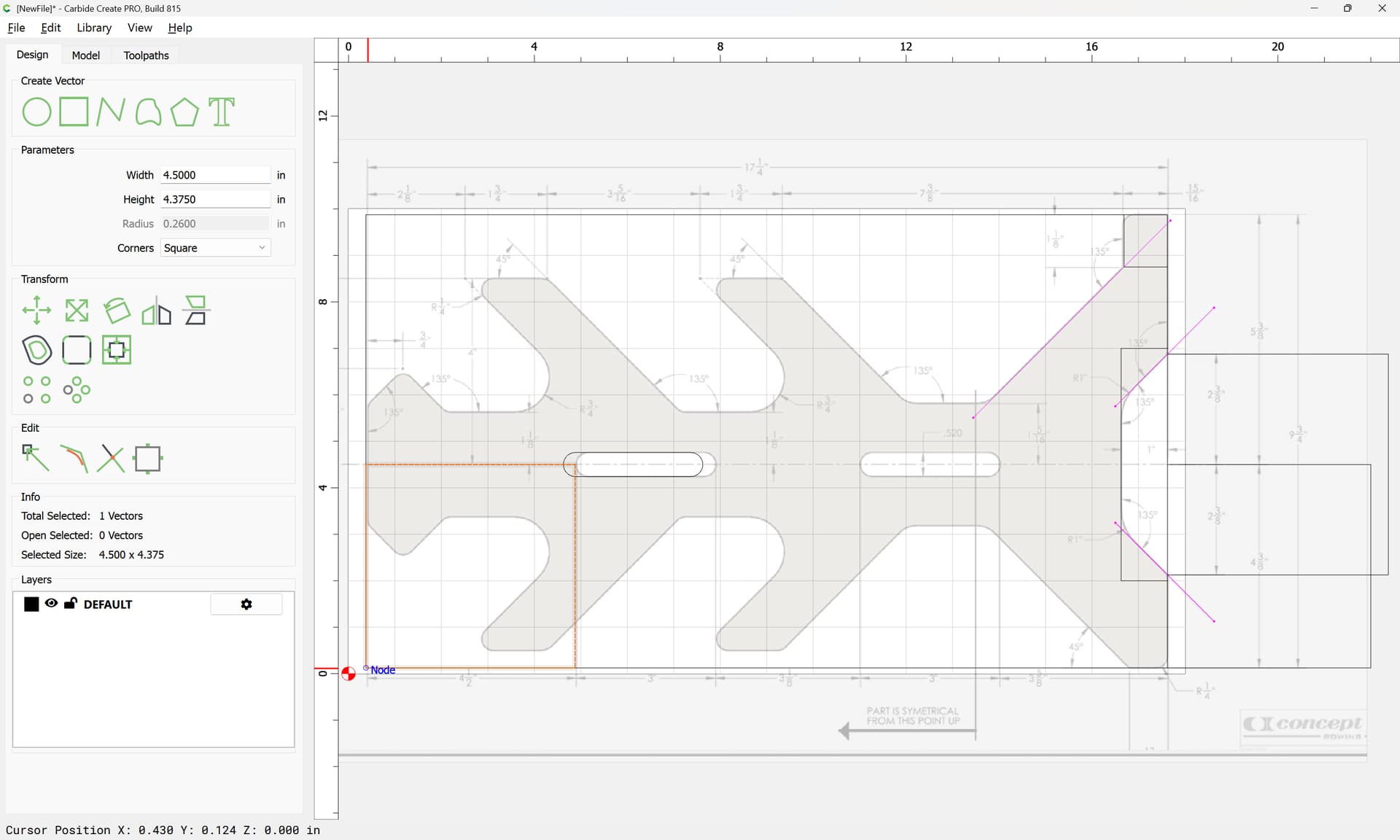
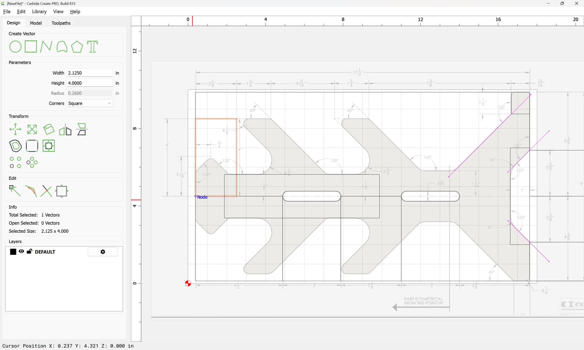
Where necessary, draw in elements for size:
and drag them into position:
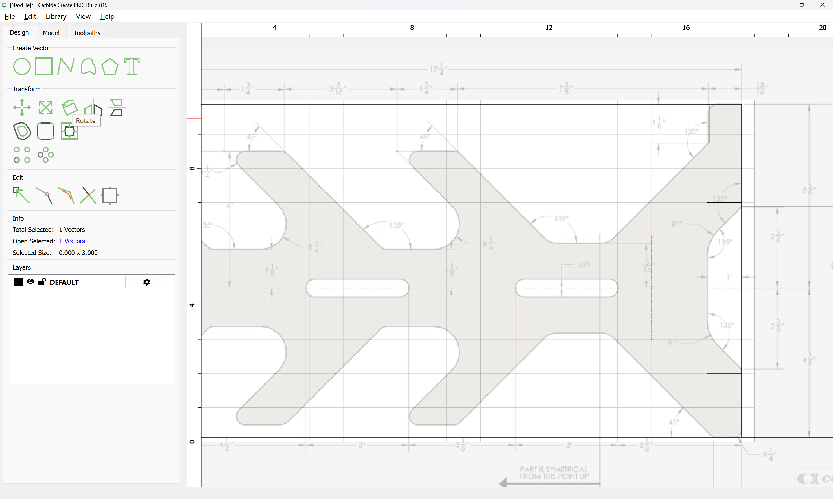
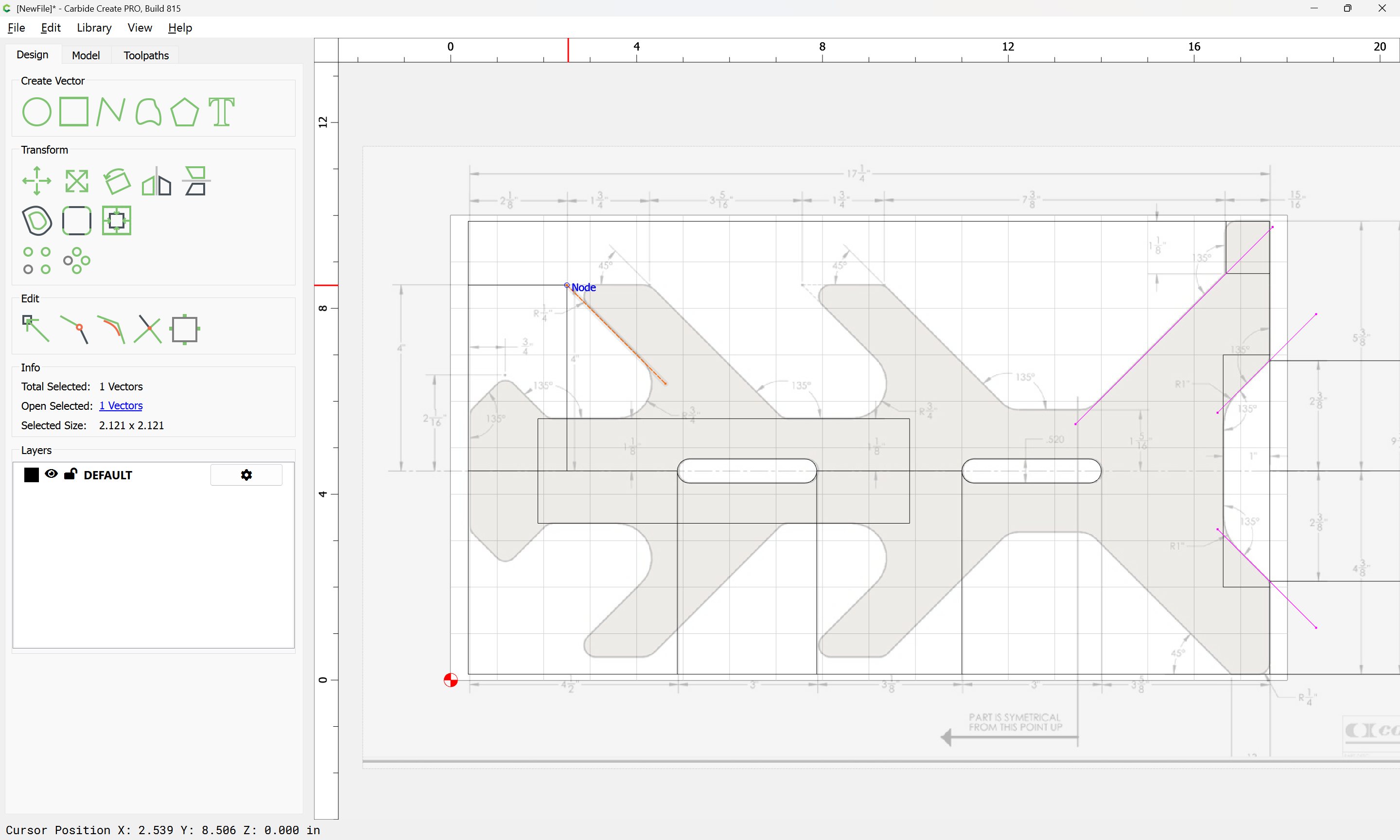
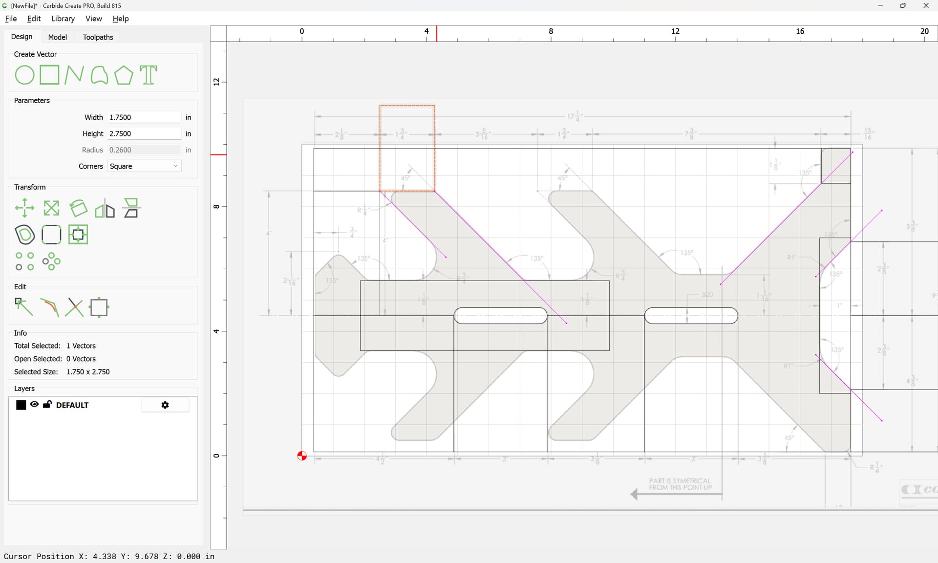
To arrive at specified angles, draw lines:
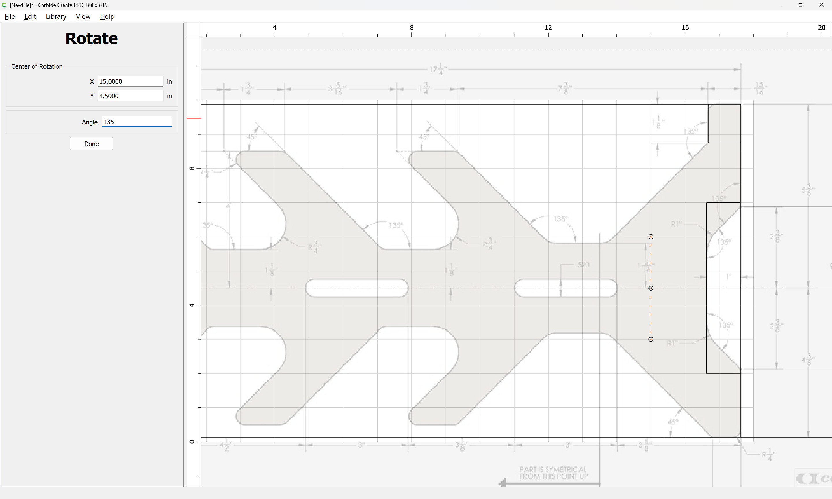
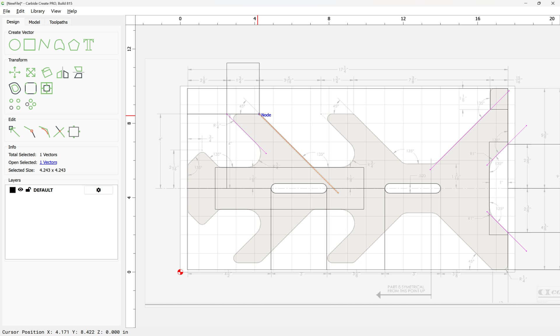
and rotate them:
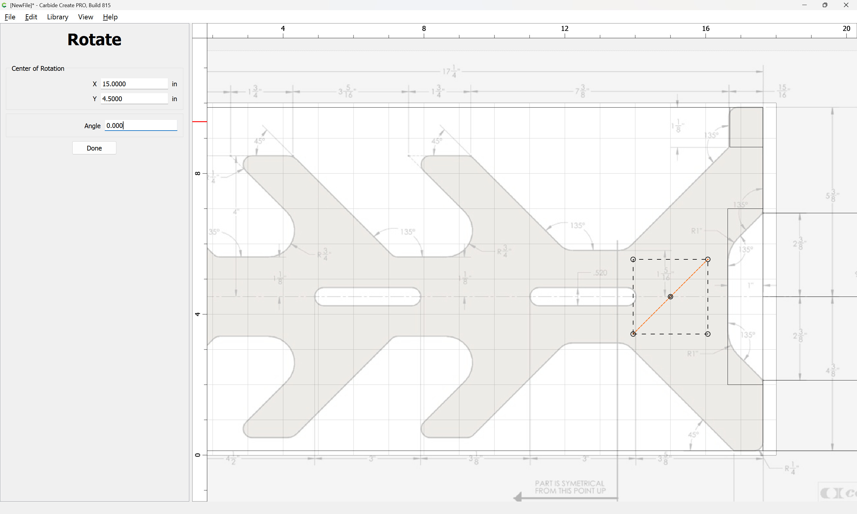
Done
and drag them into place:
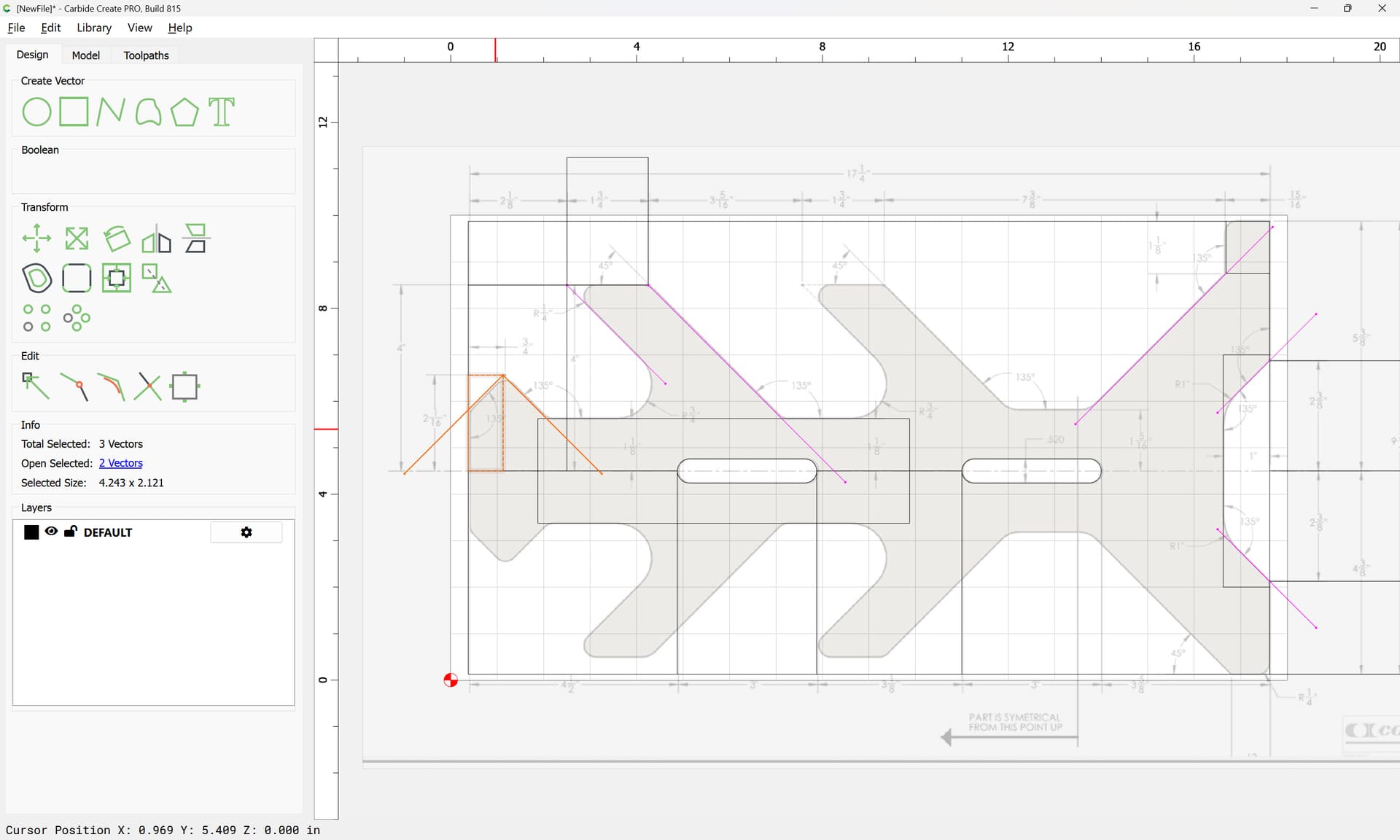
Symmetrical elements may be duplicated:
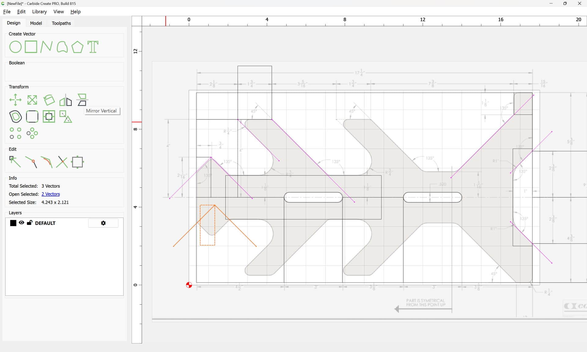
and mirrored:
and dragged into place:
It will be helpful to have thing cross, rather than touch, so using the arrow keys to move in even grid increments:


will assist in this.
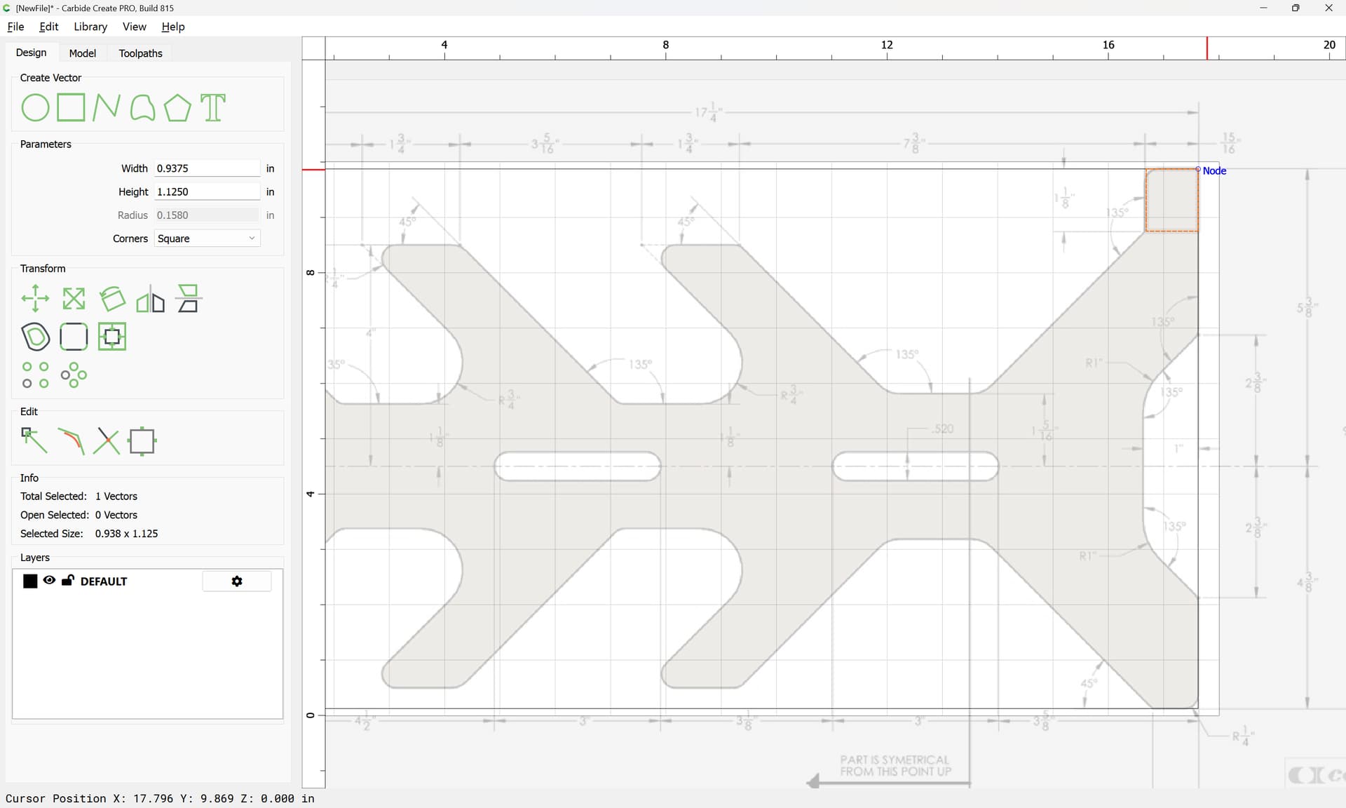
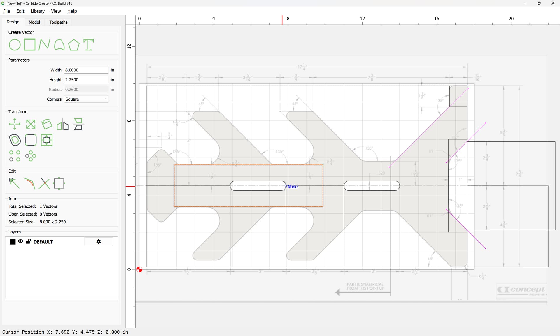
Draw in elements:
and geometry to position them:
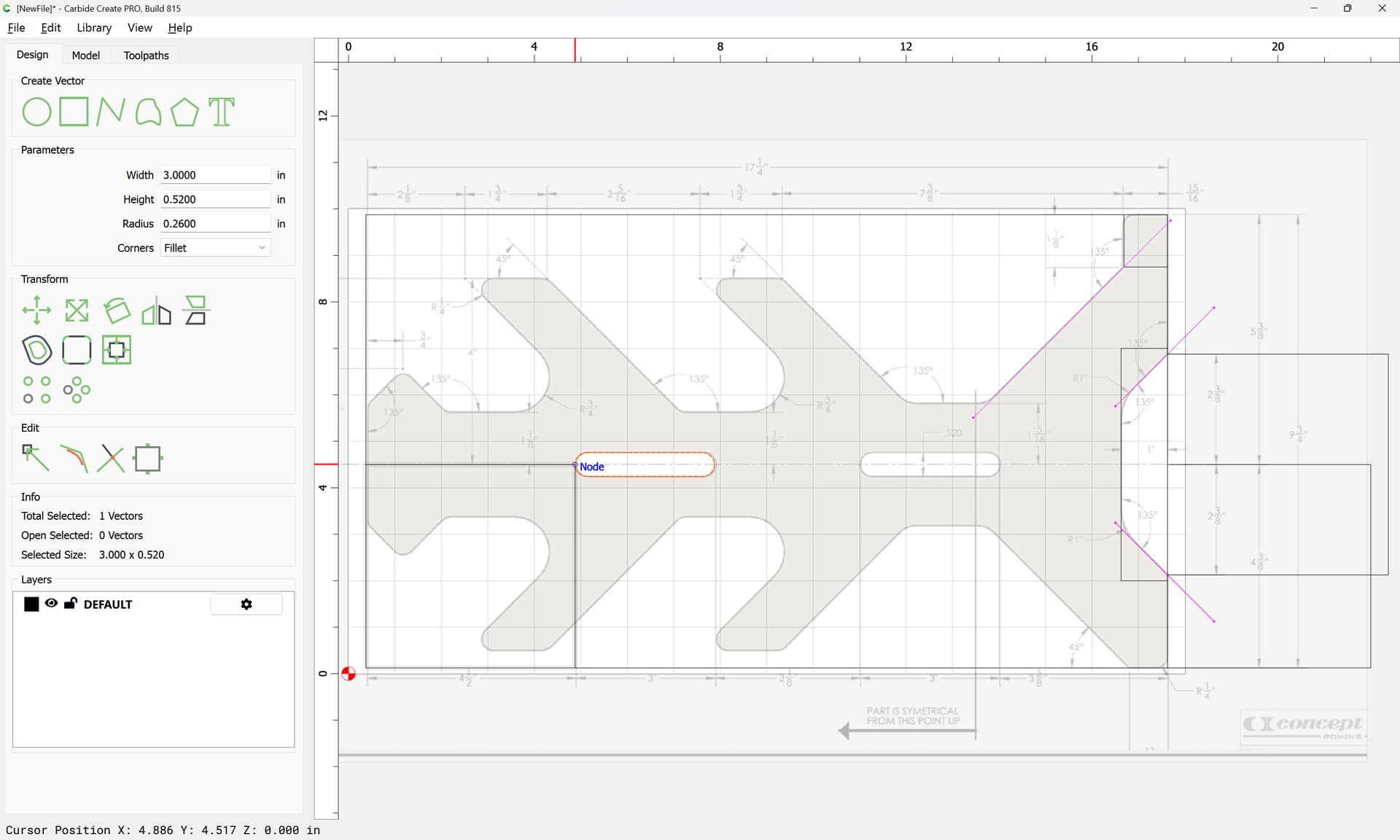

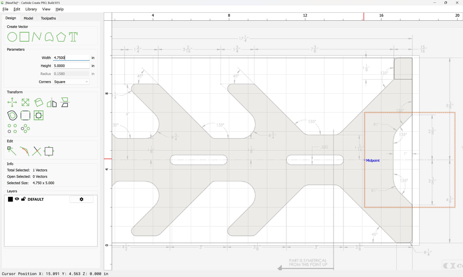
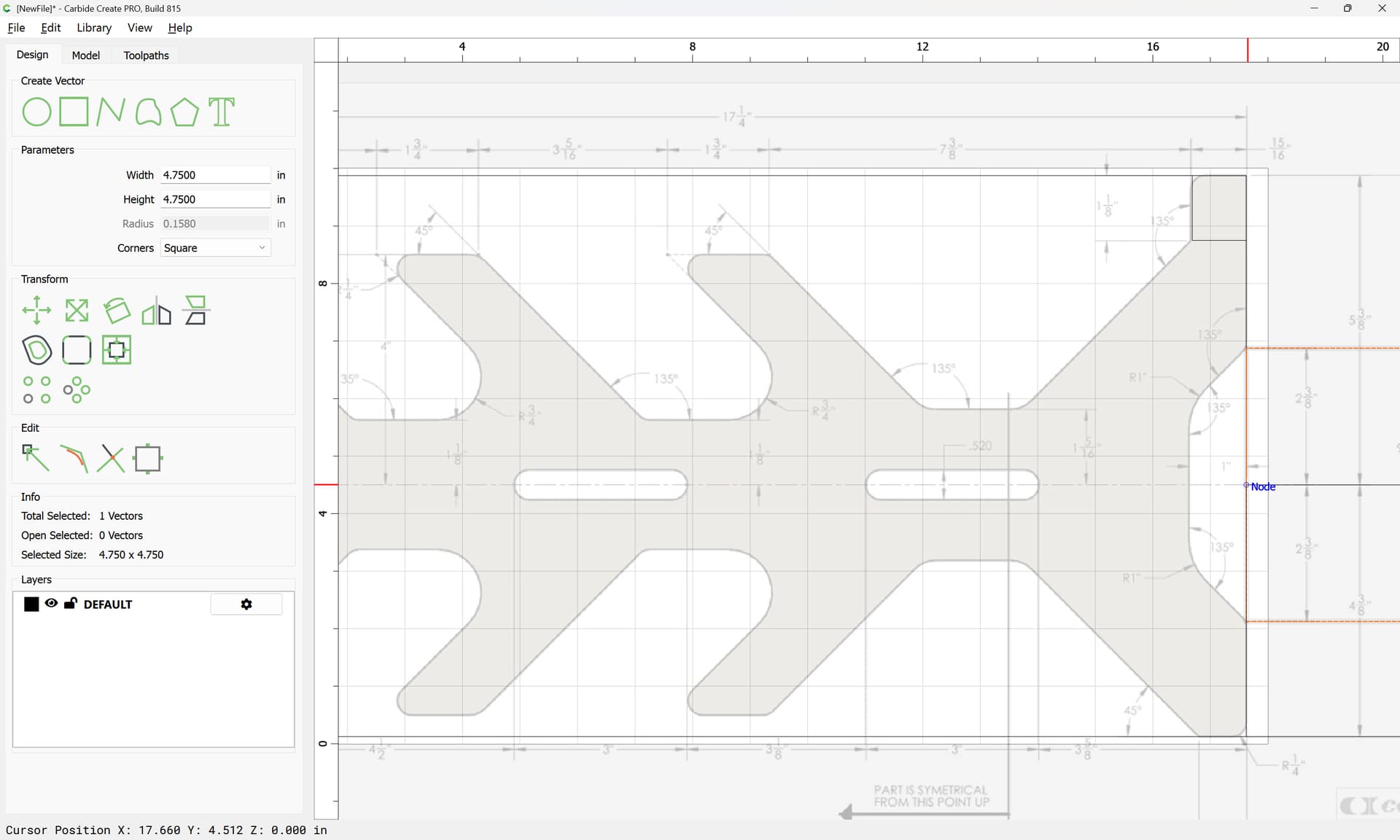
Positioning things as dimensions indicate:
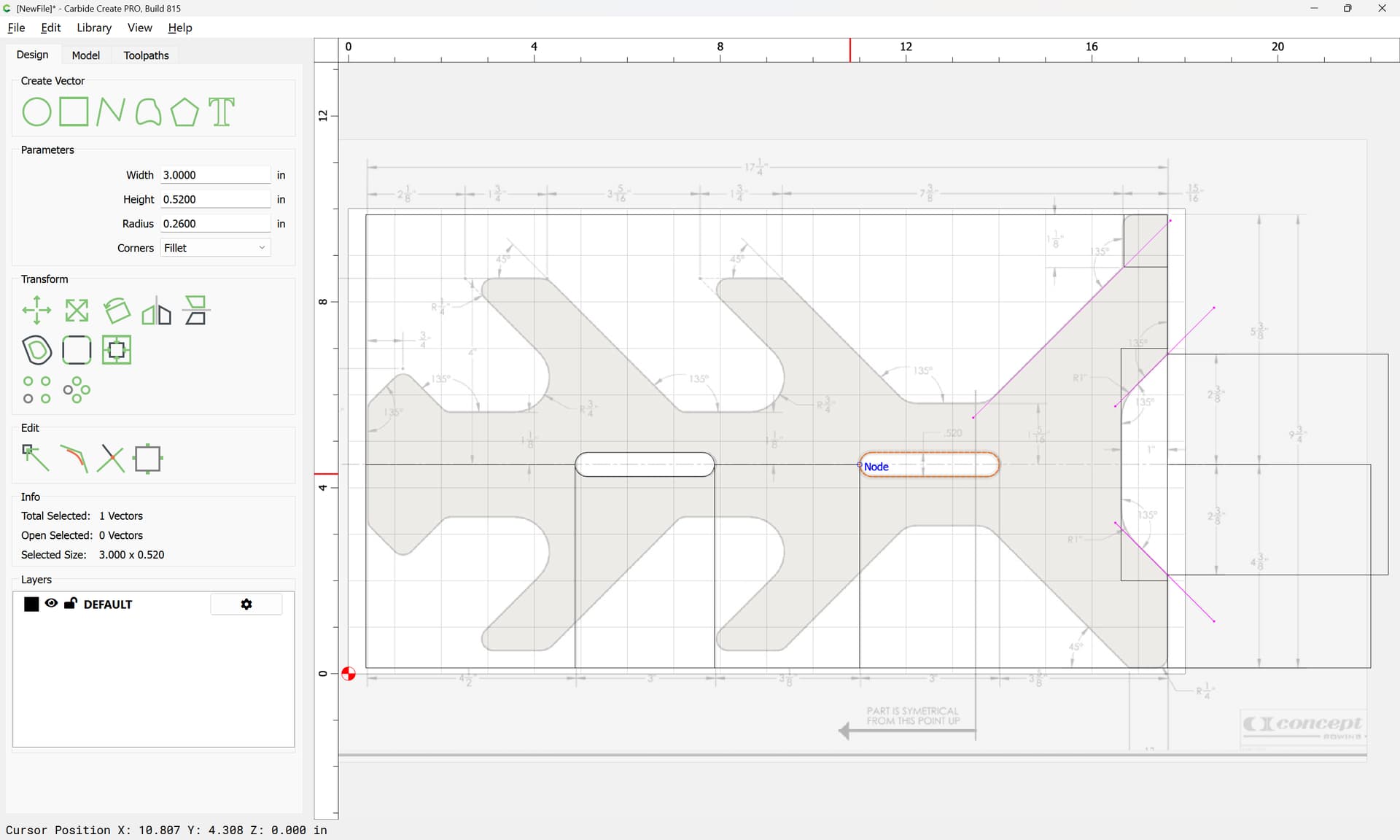
Drawing elements as appropriate:

Where appropriate duplicate symmetric elements:

Dragging the duplicates into alignment:
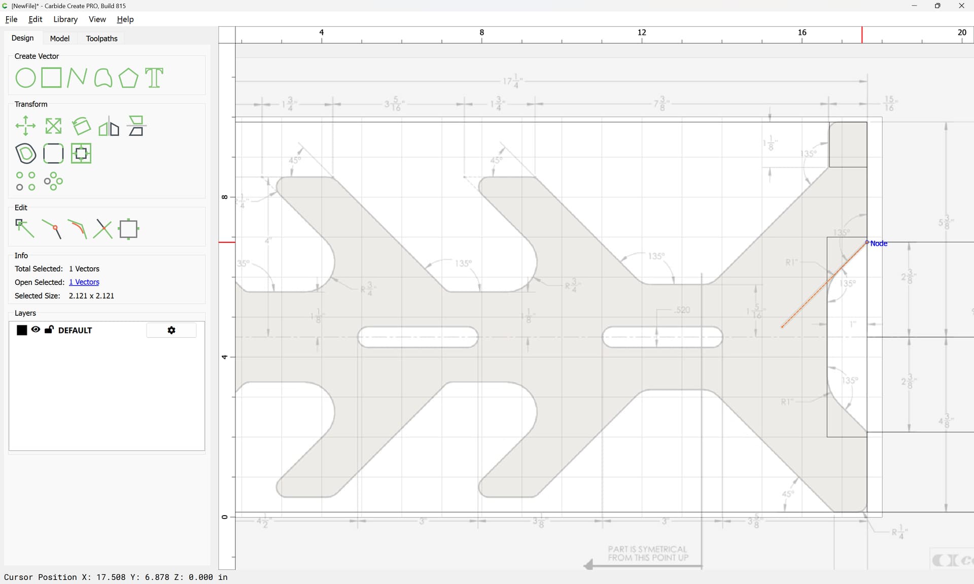
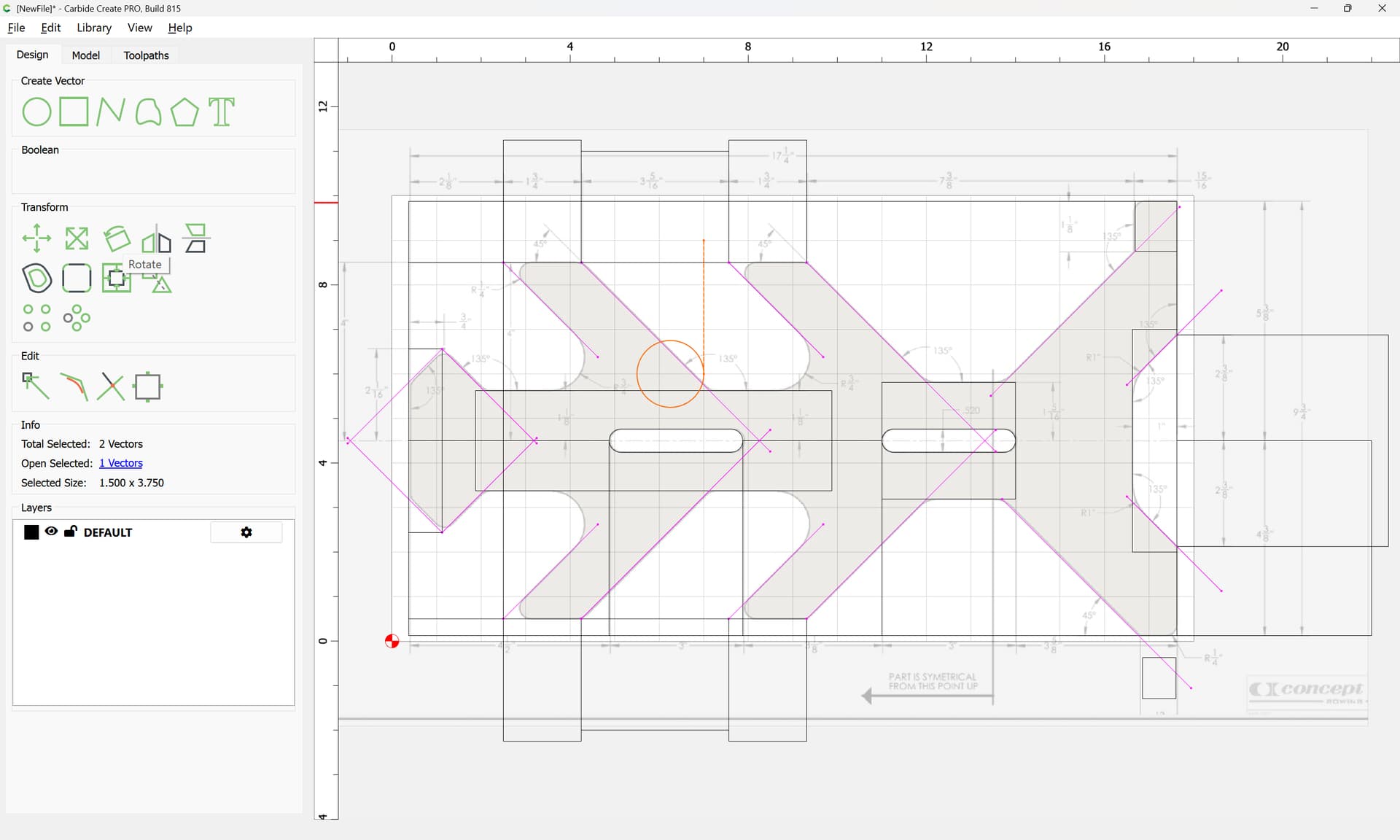
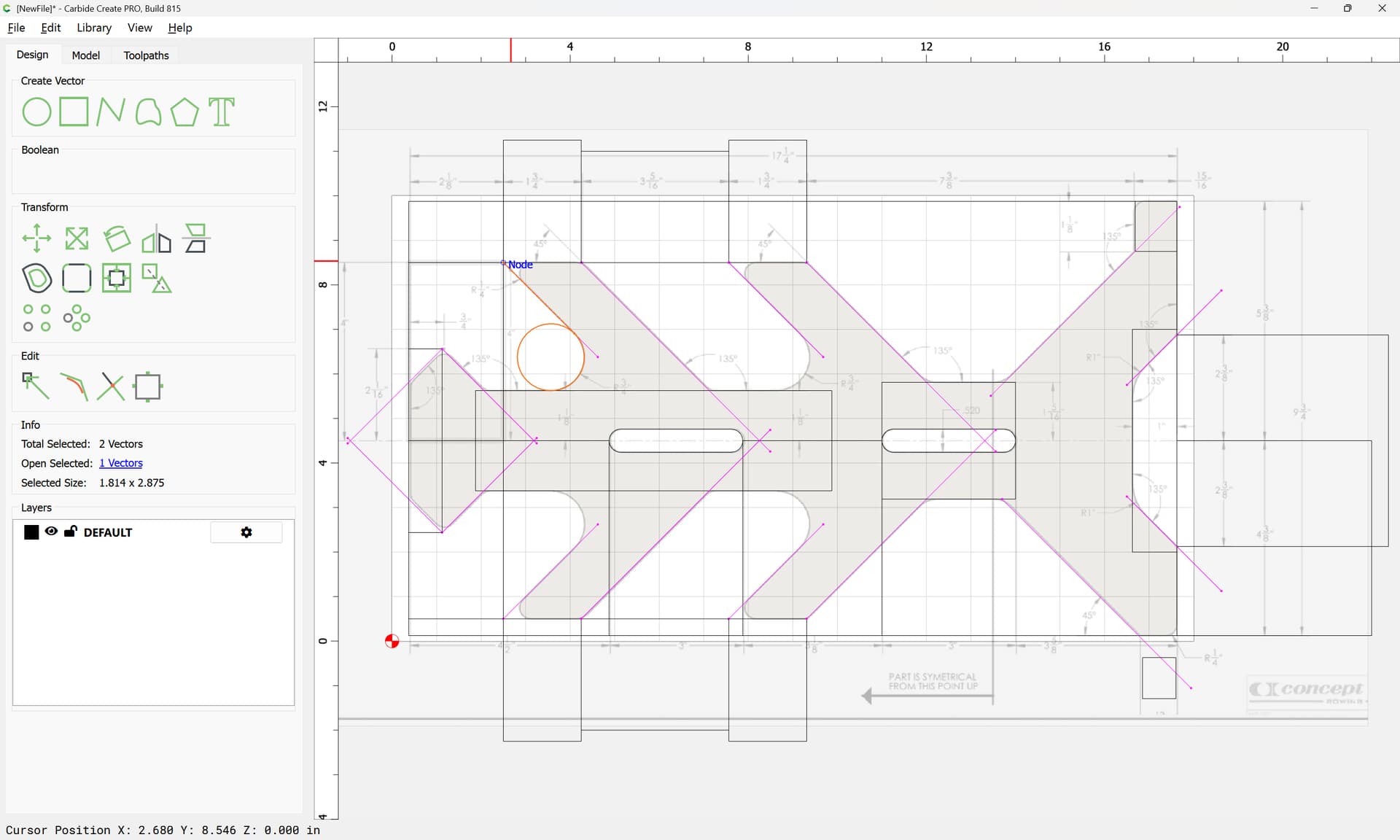
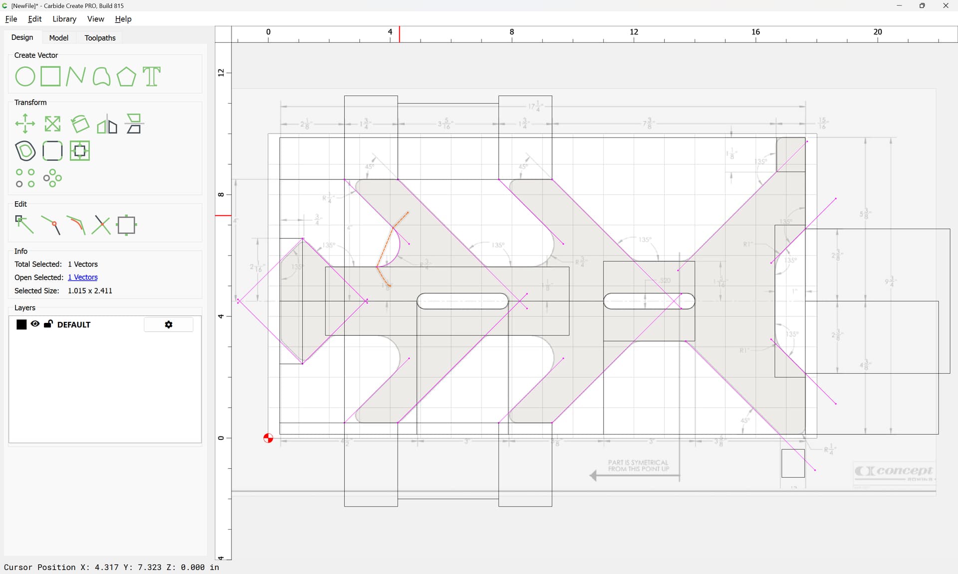
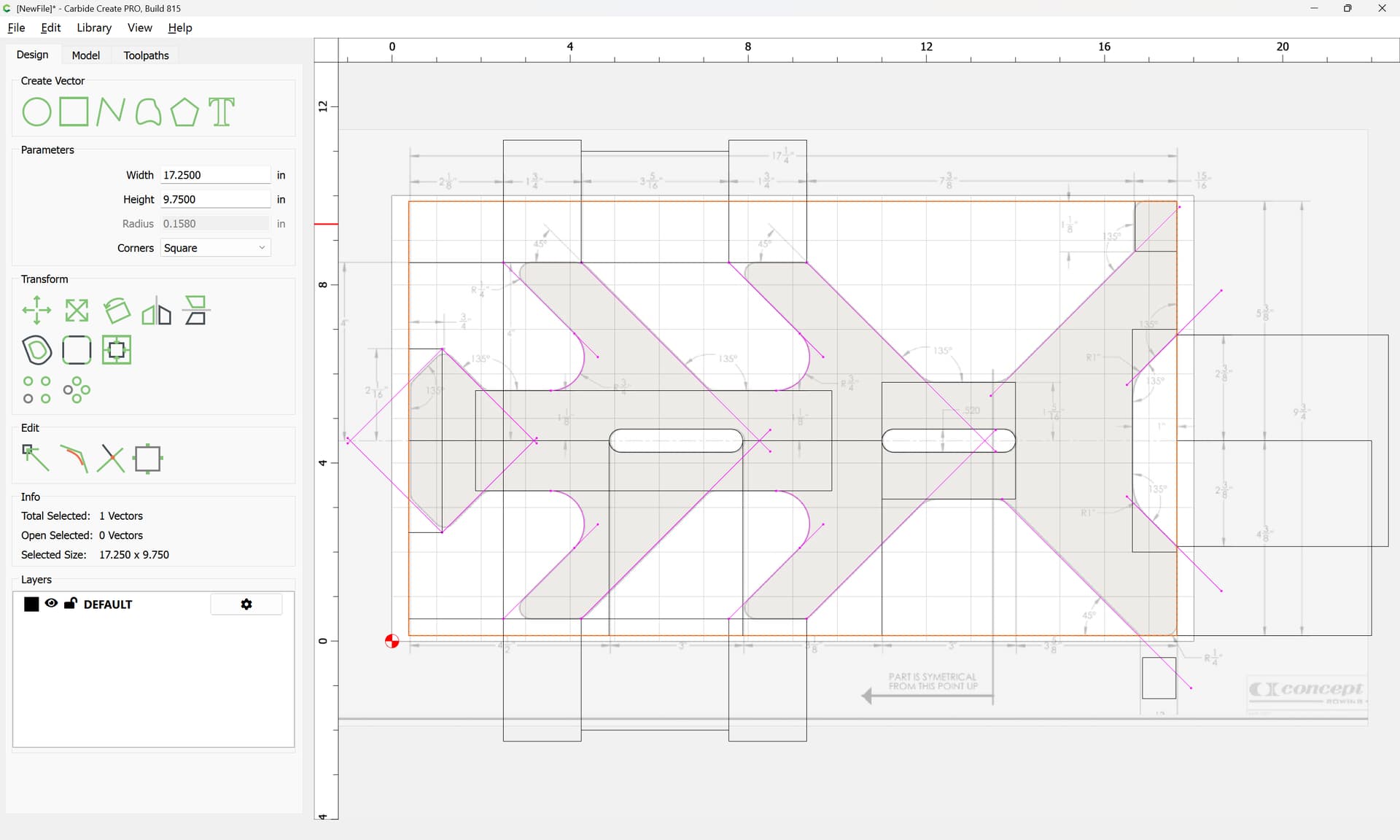
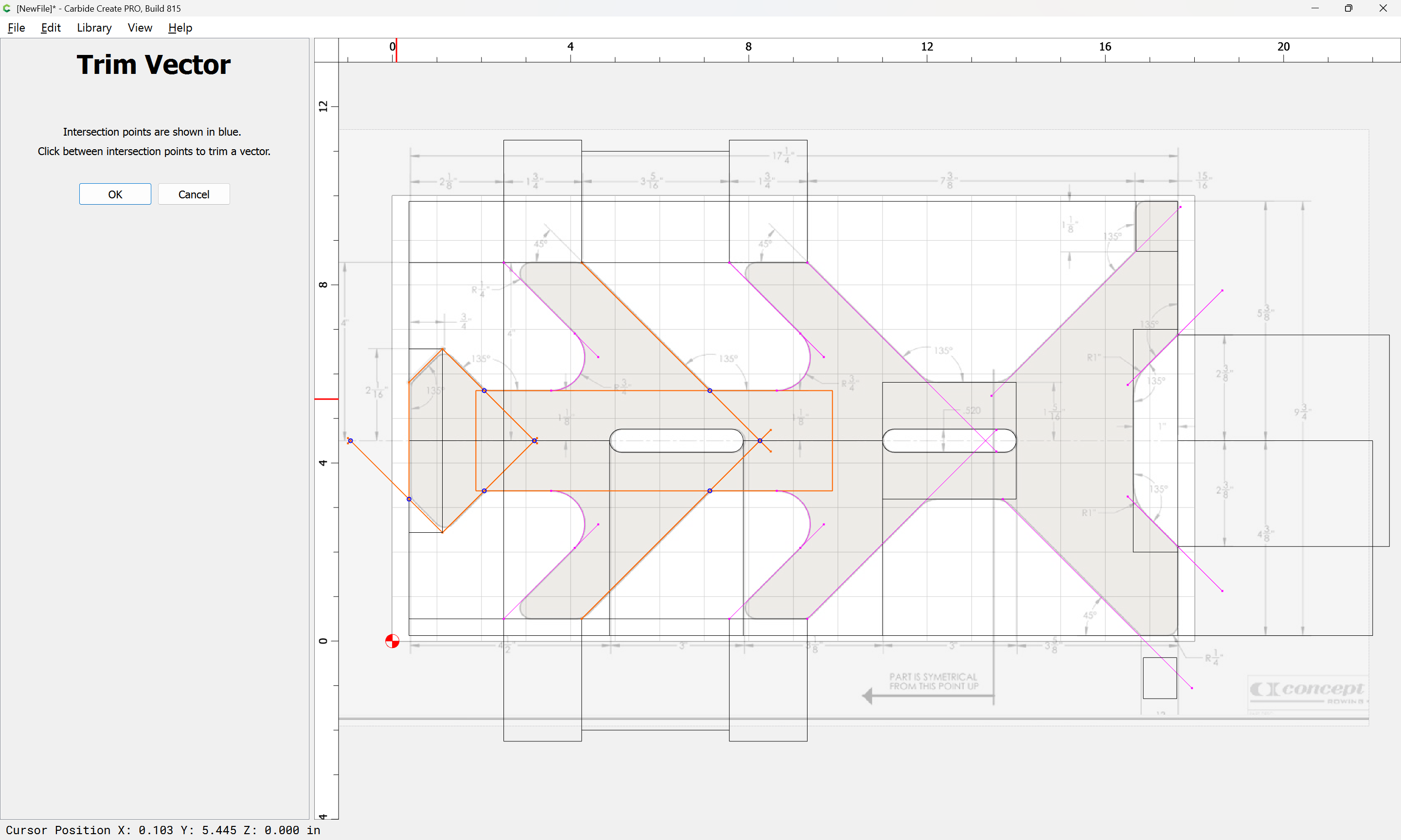
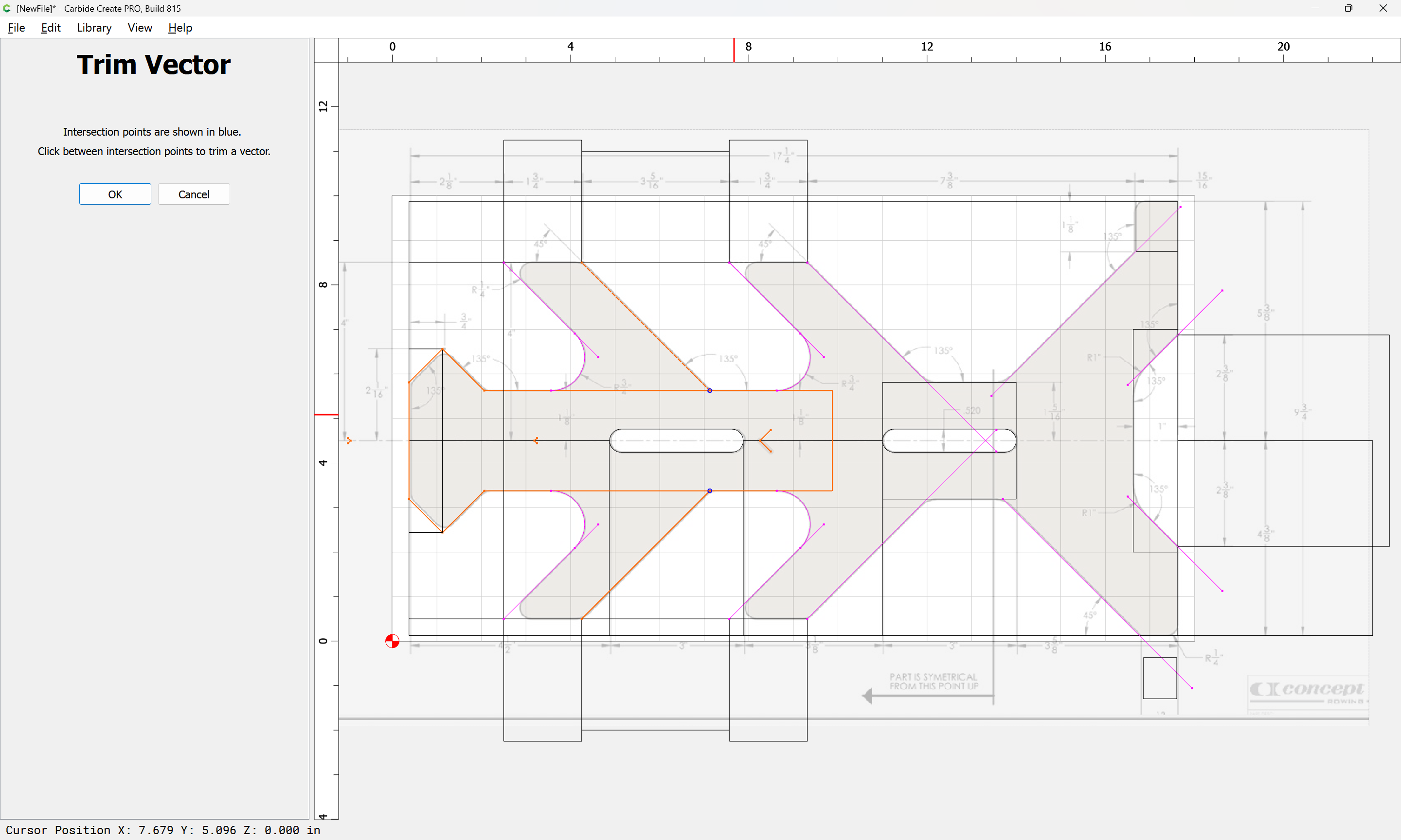
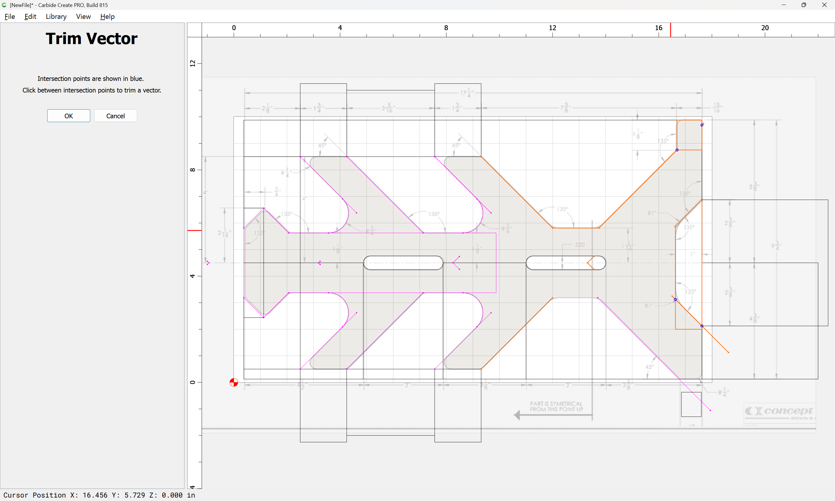
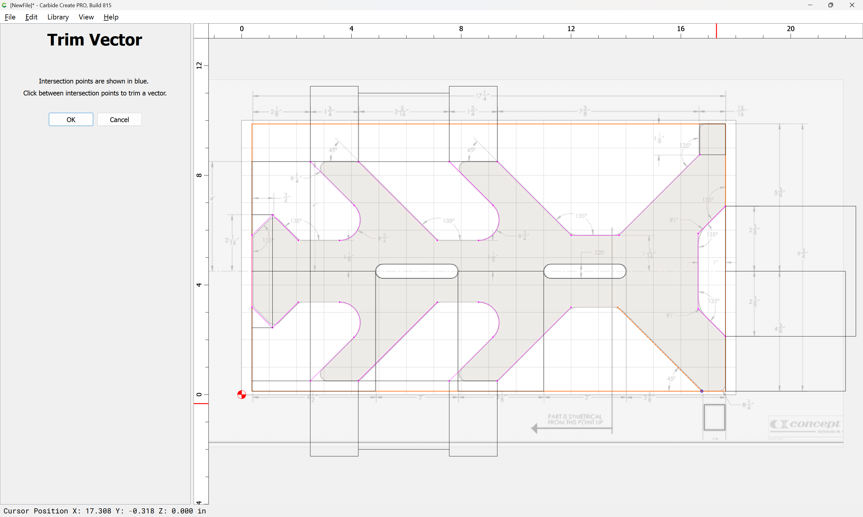
Where a tangent is needed, draw a circle and an aligning line:
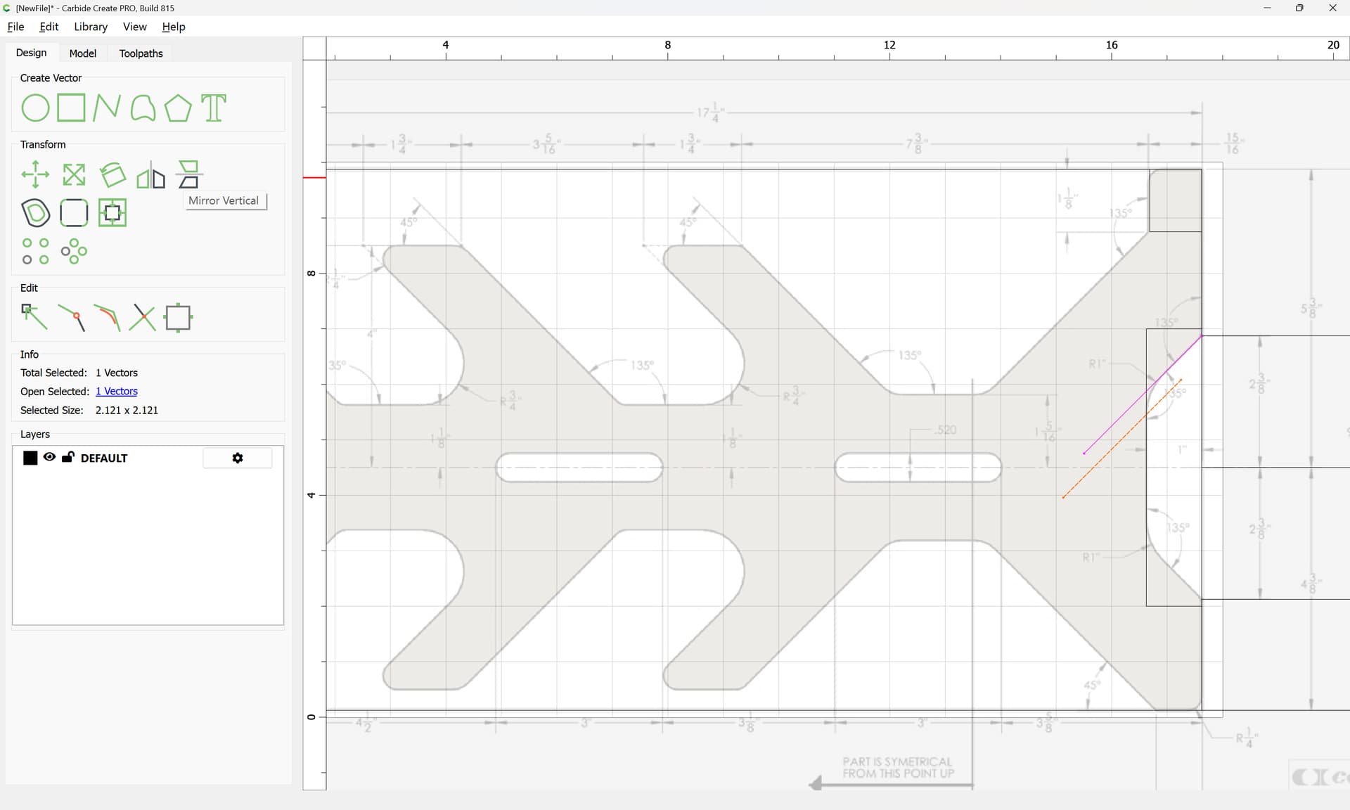
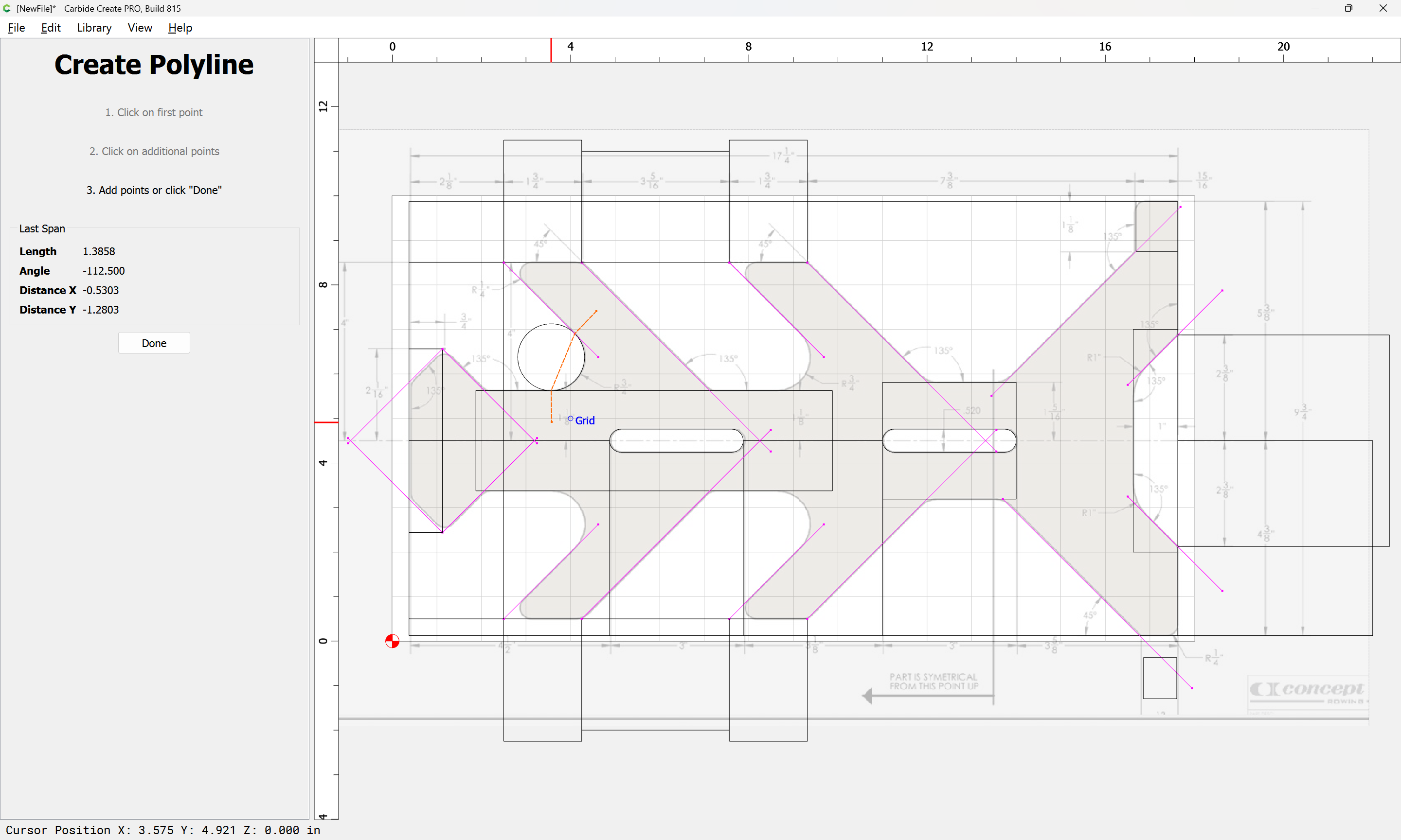
and rotate:
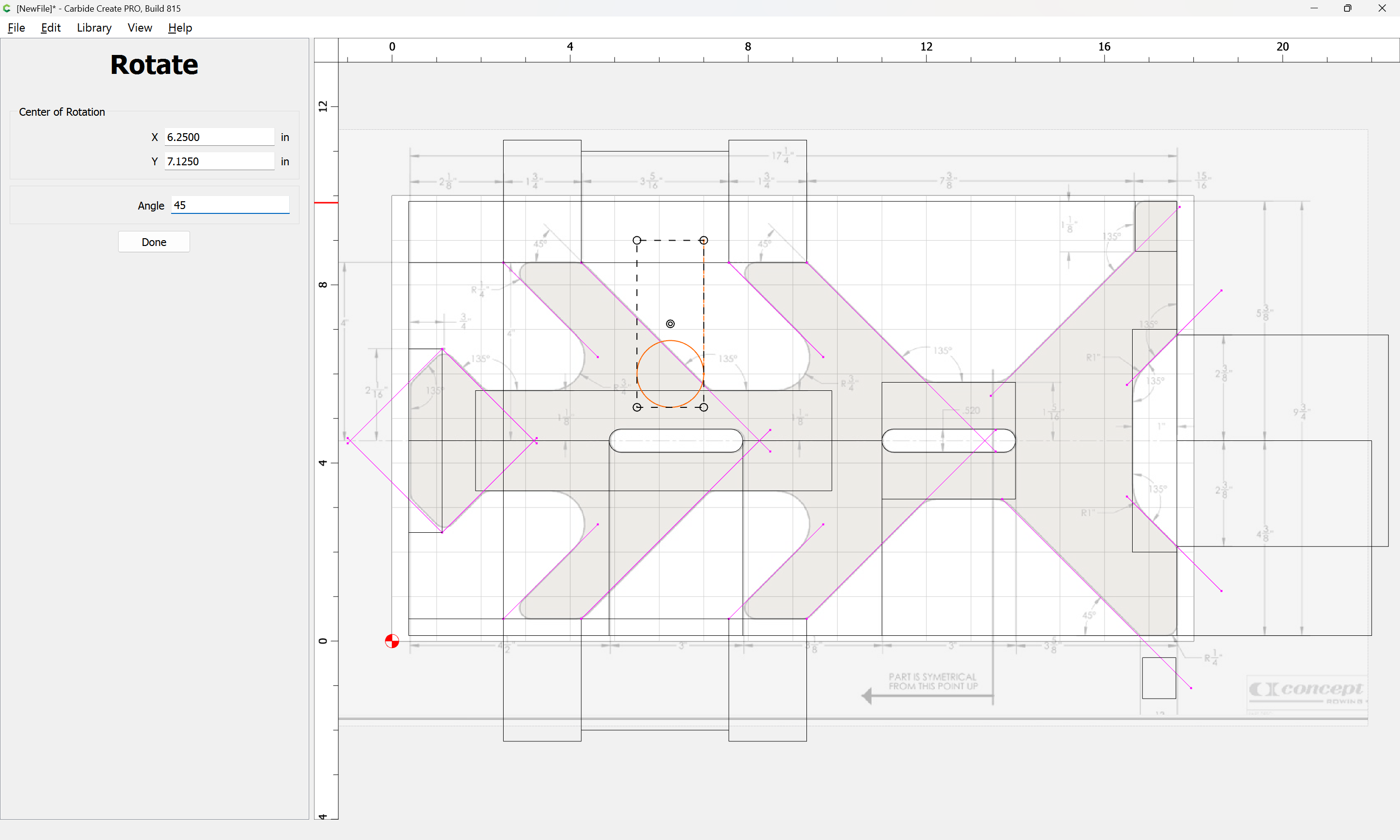
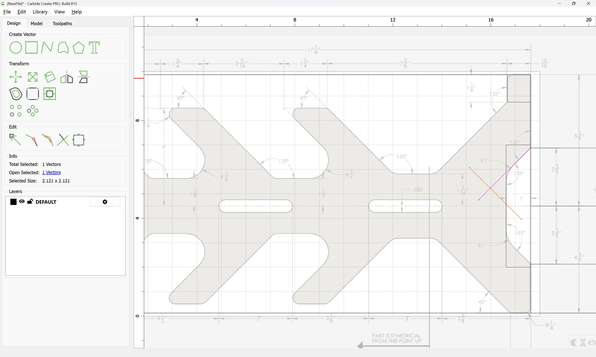
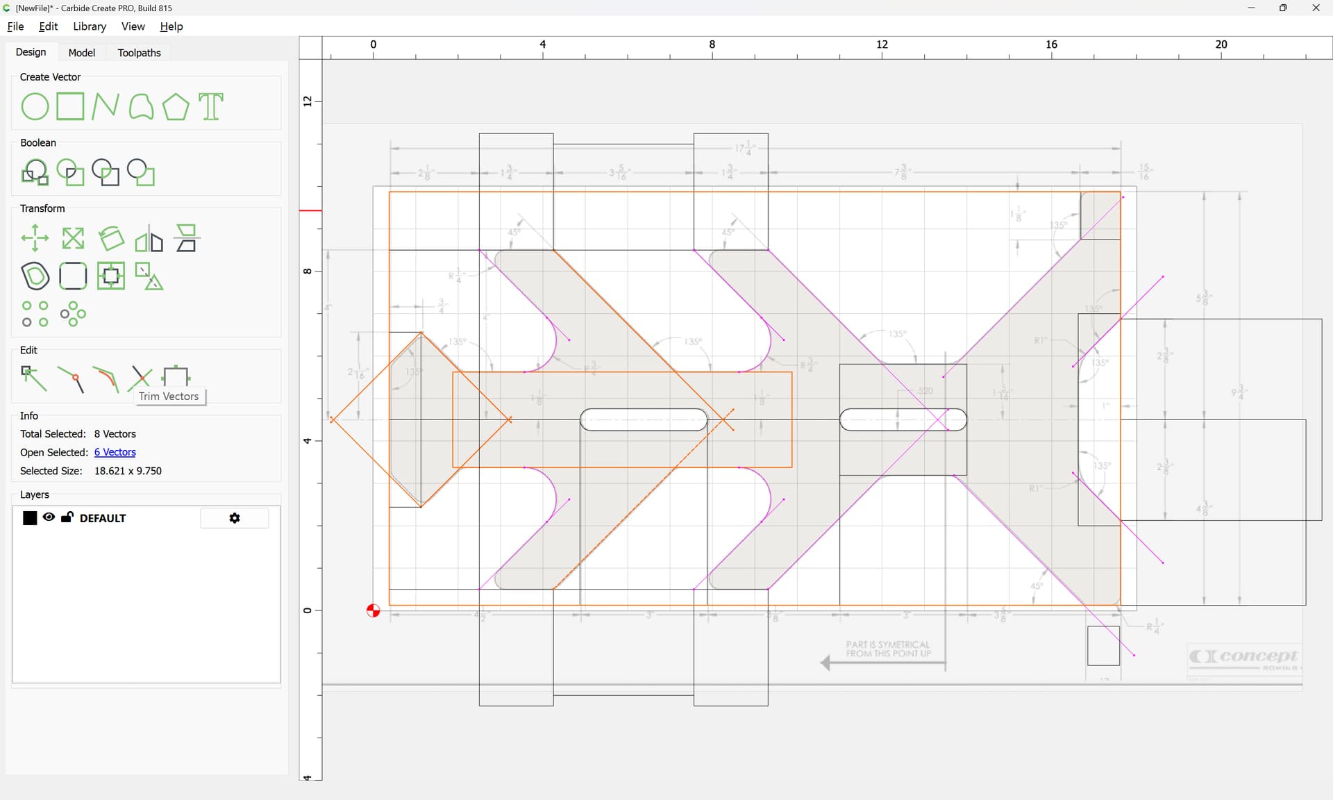
Then drag it into alignment:
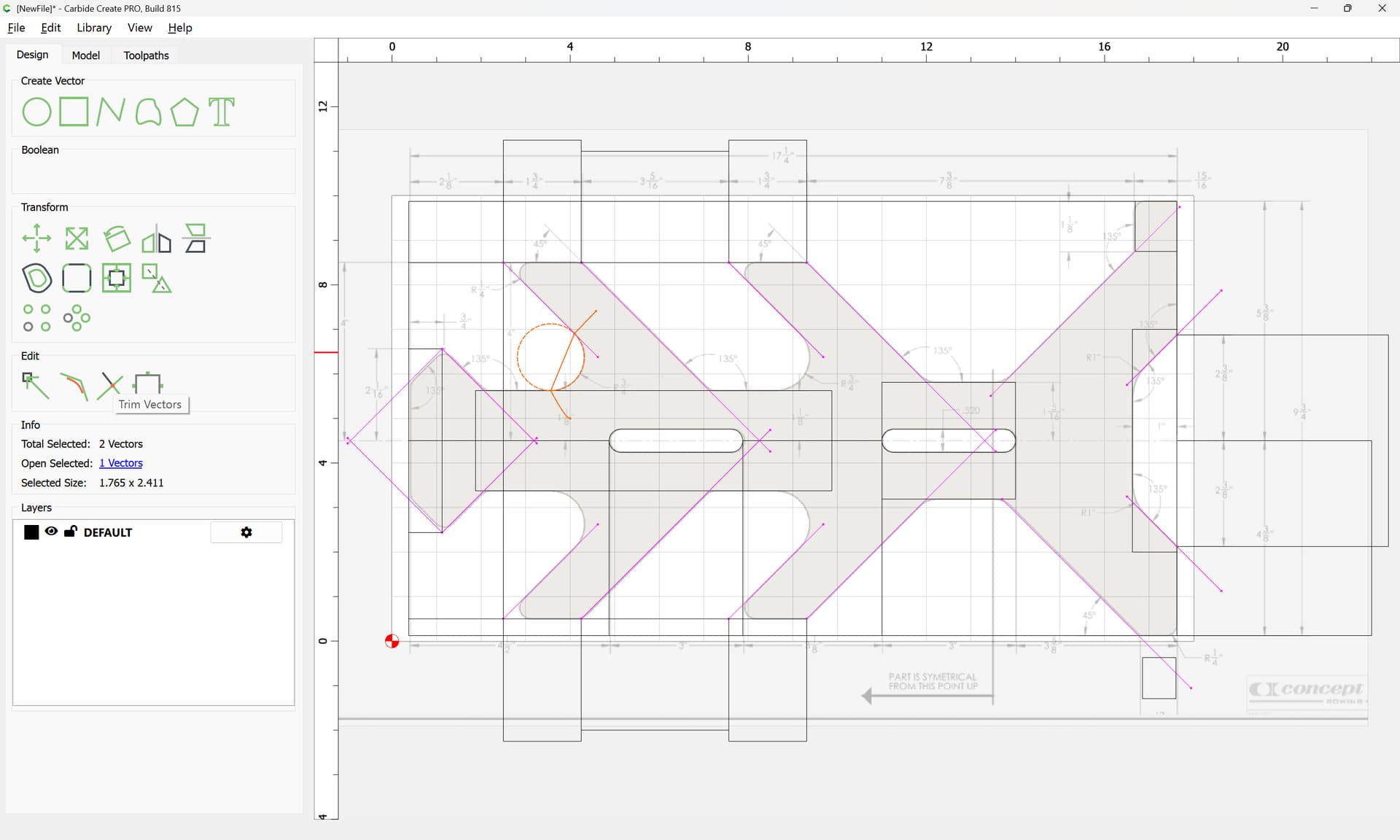
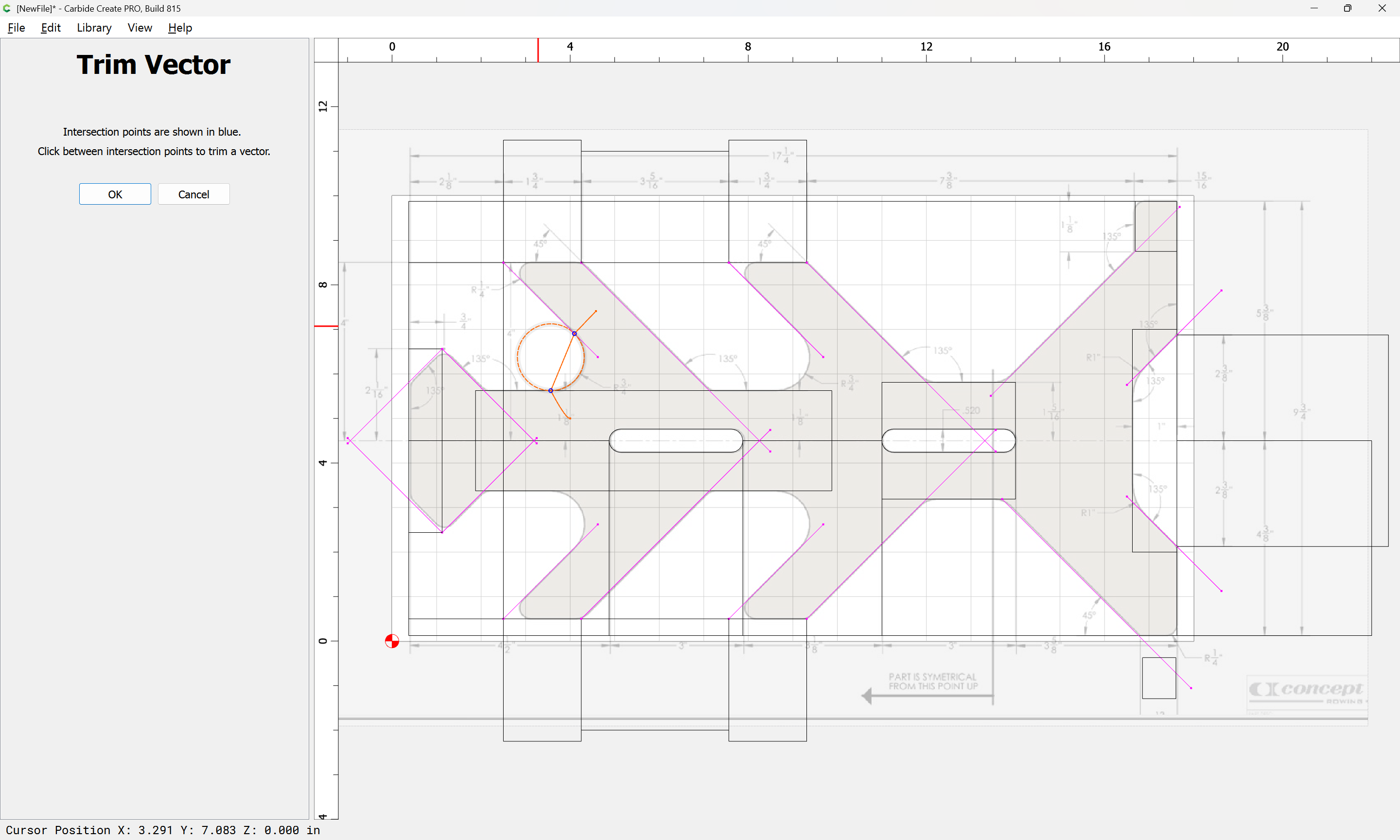
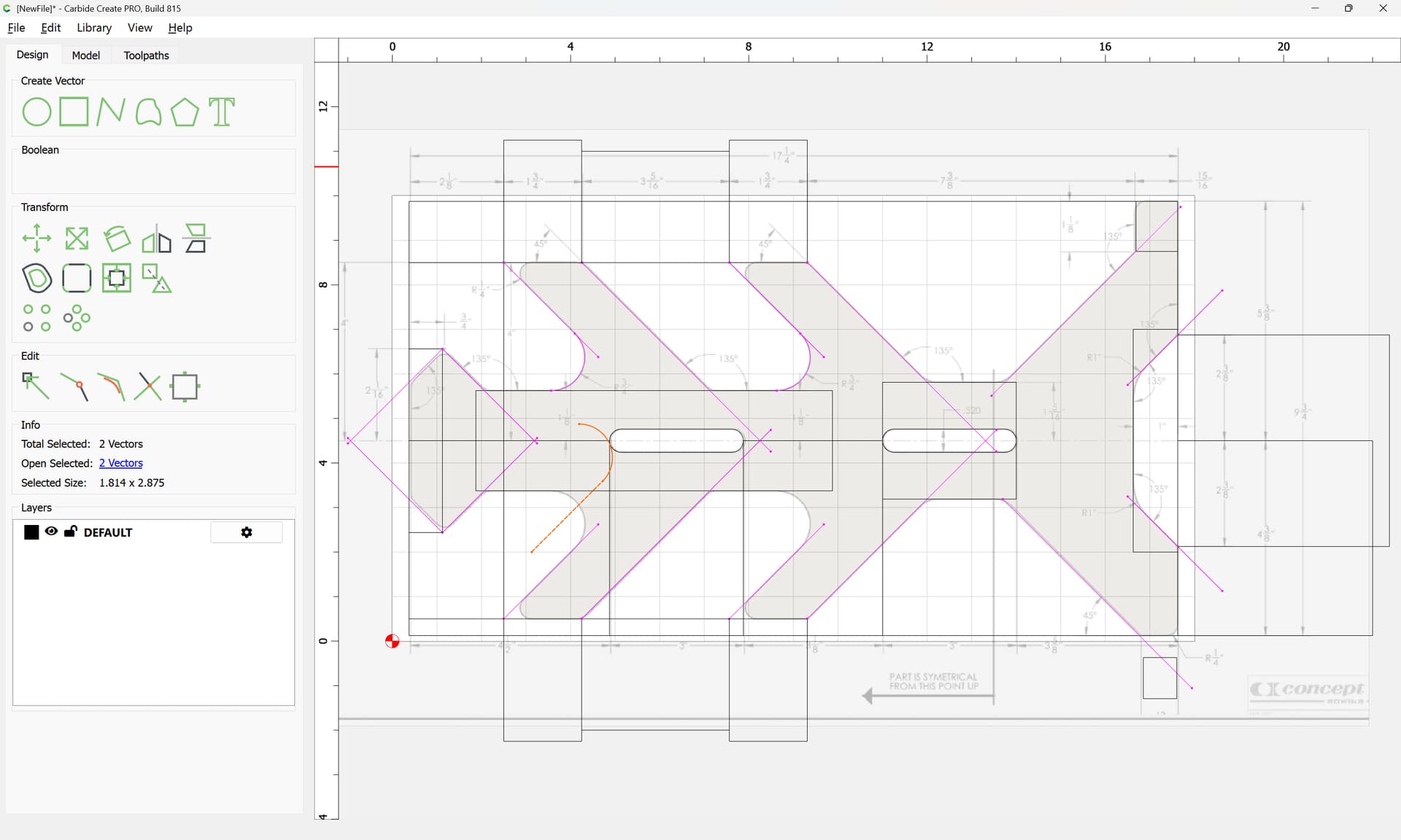
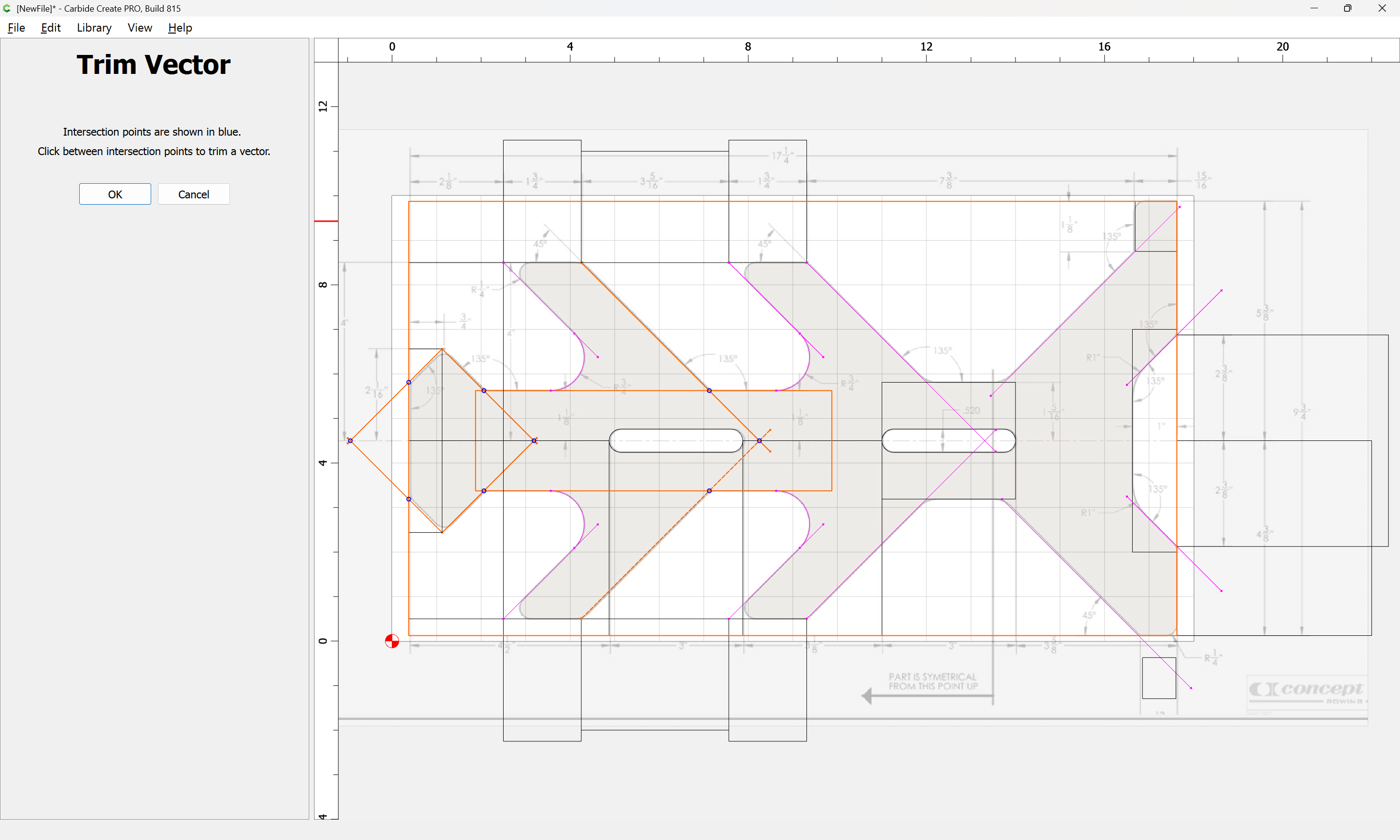
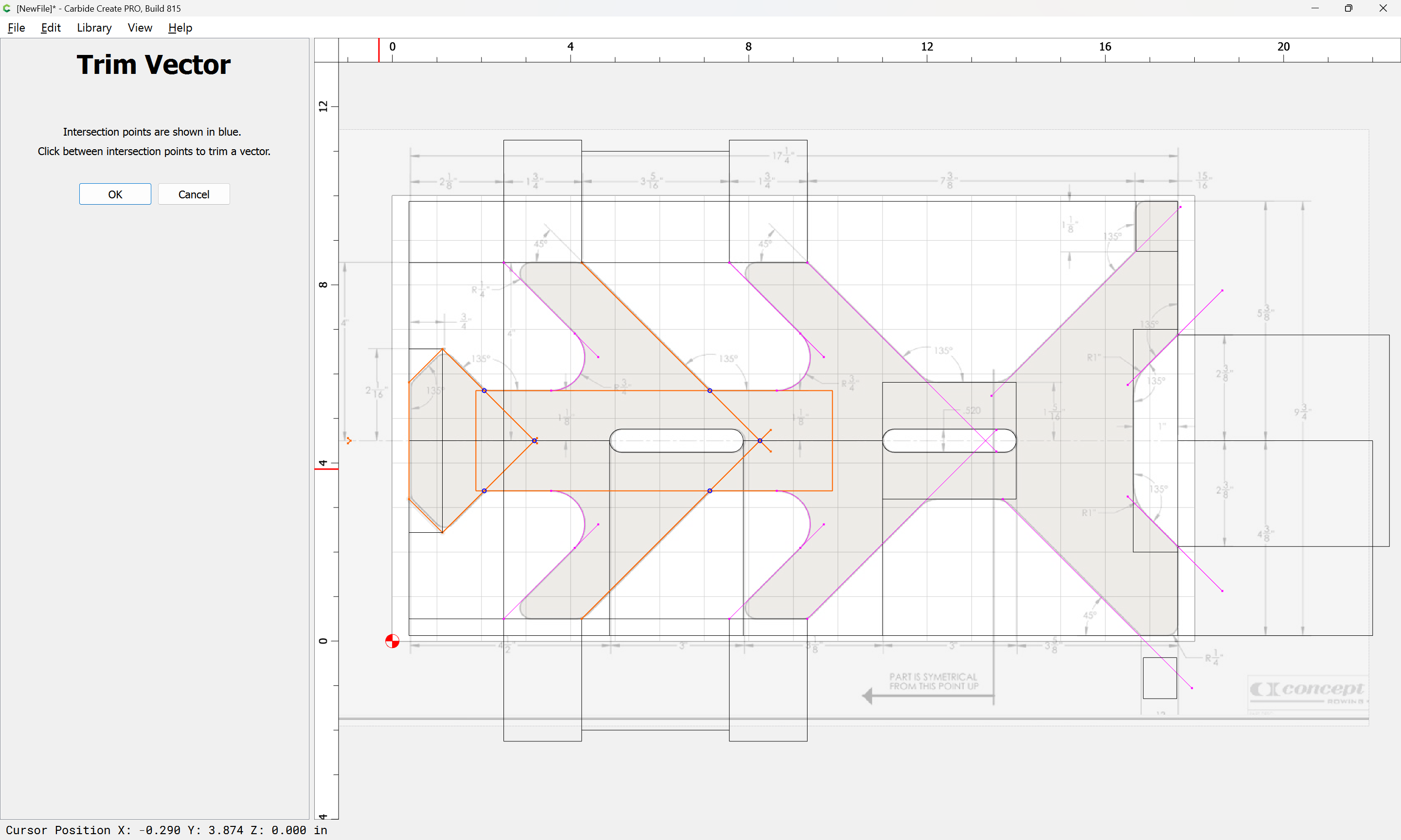
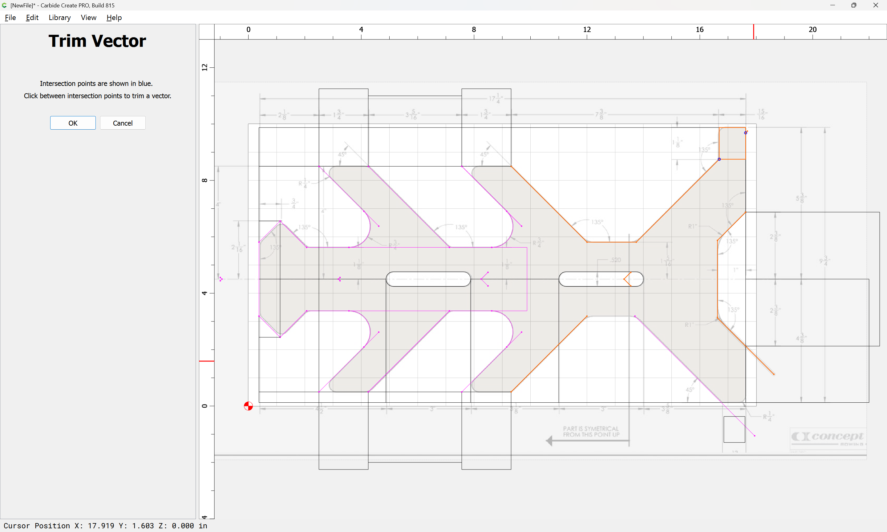
and use Trim Vectors to cut it off so that it will align:


OK

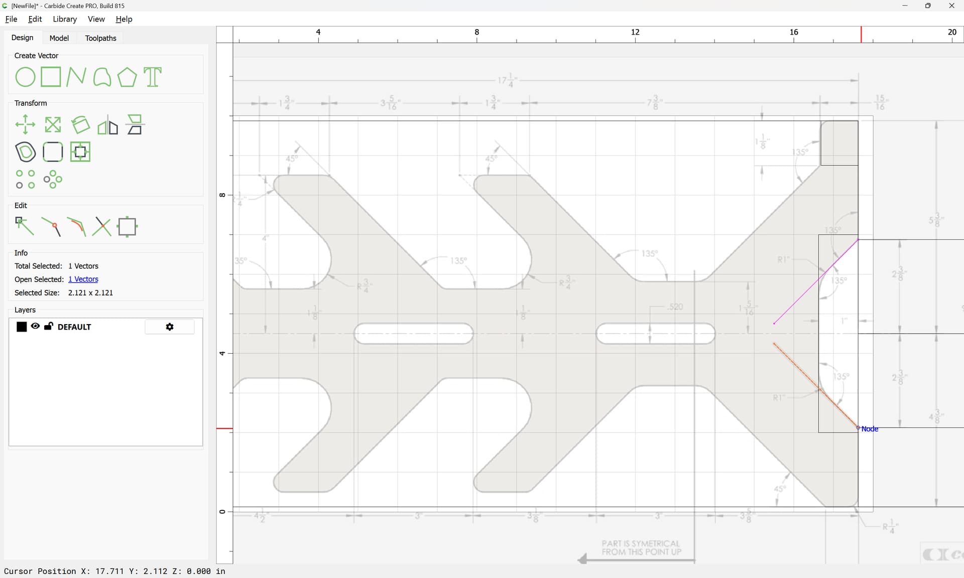
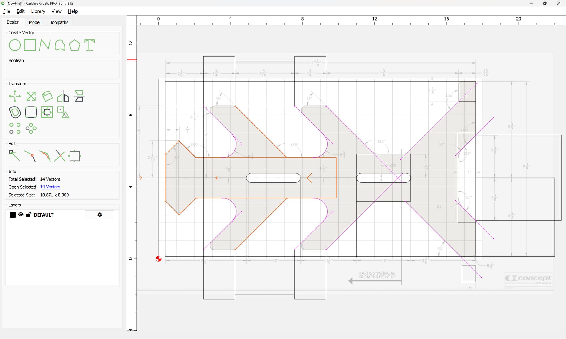
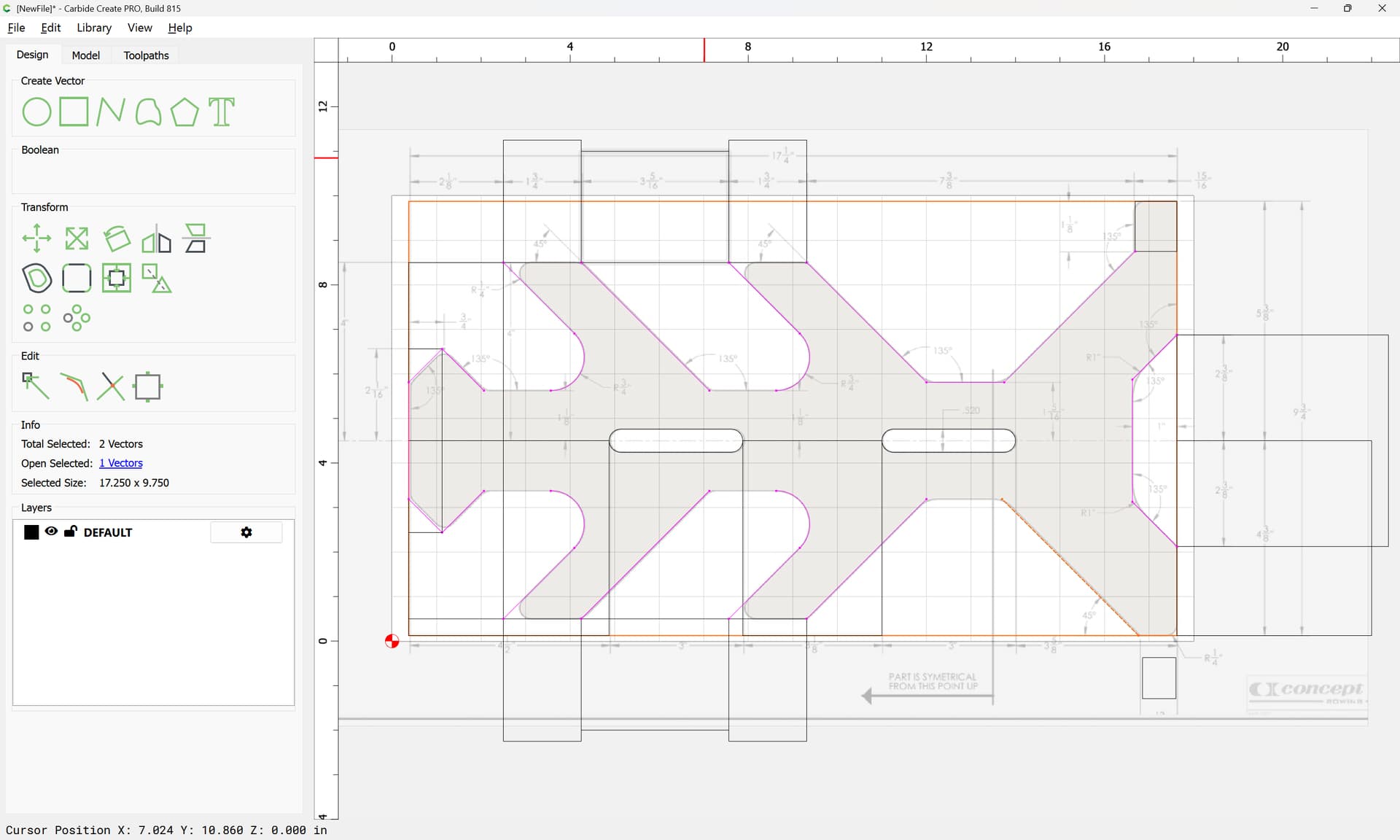
and then drag it into alignment:
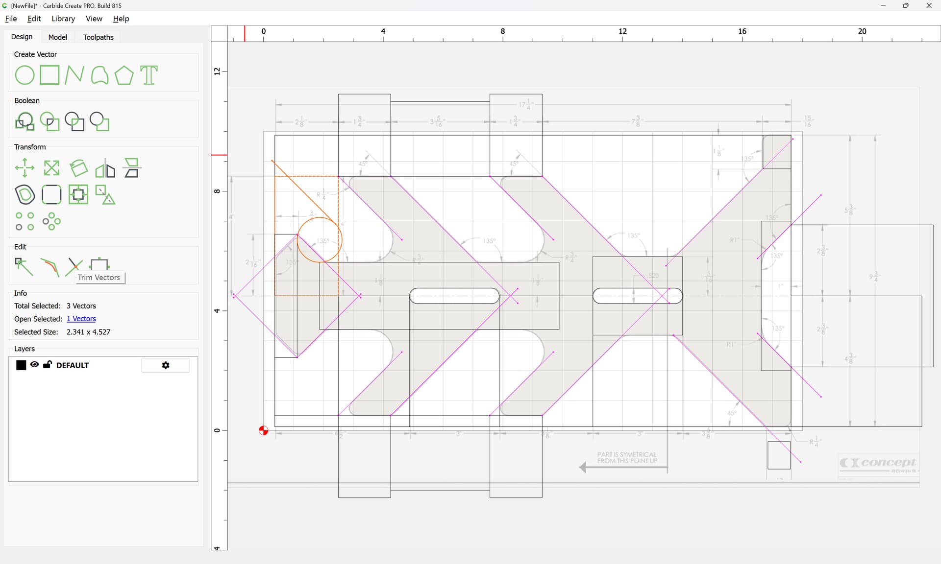
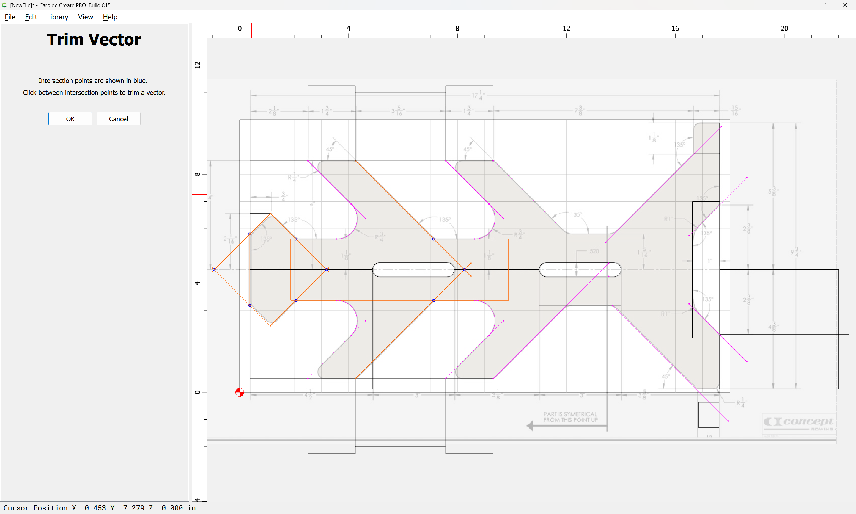
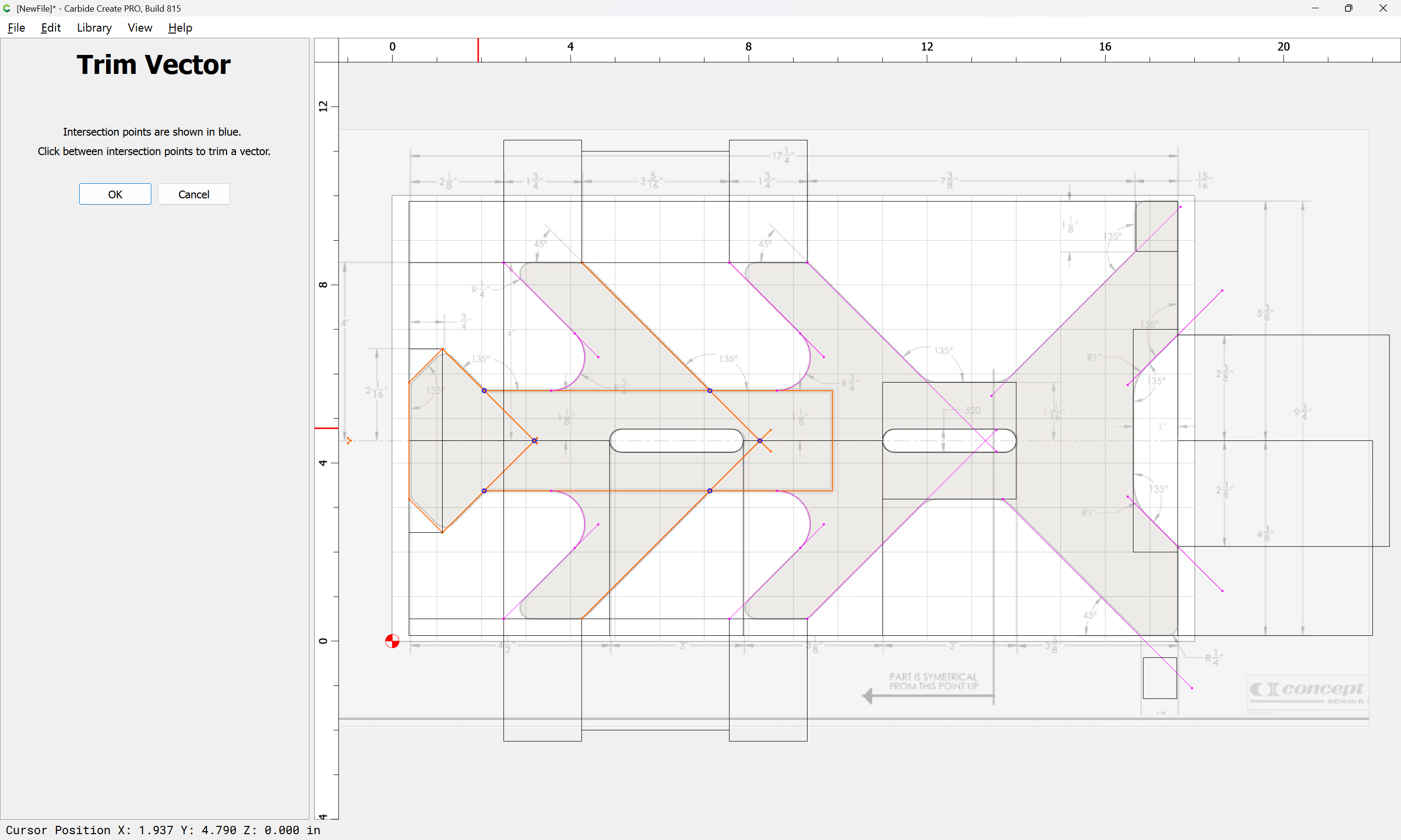
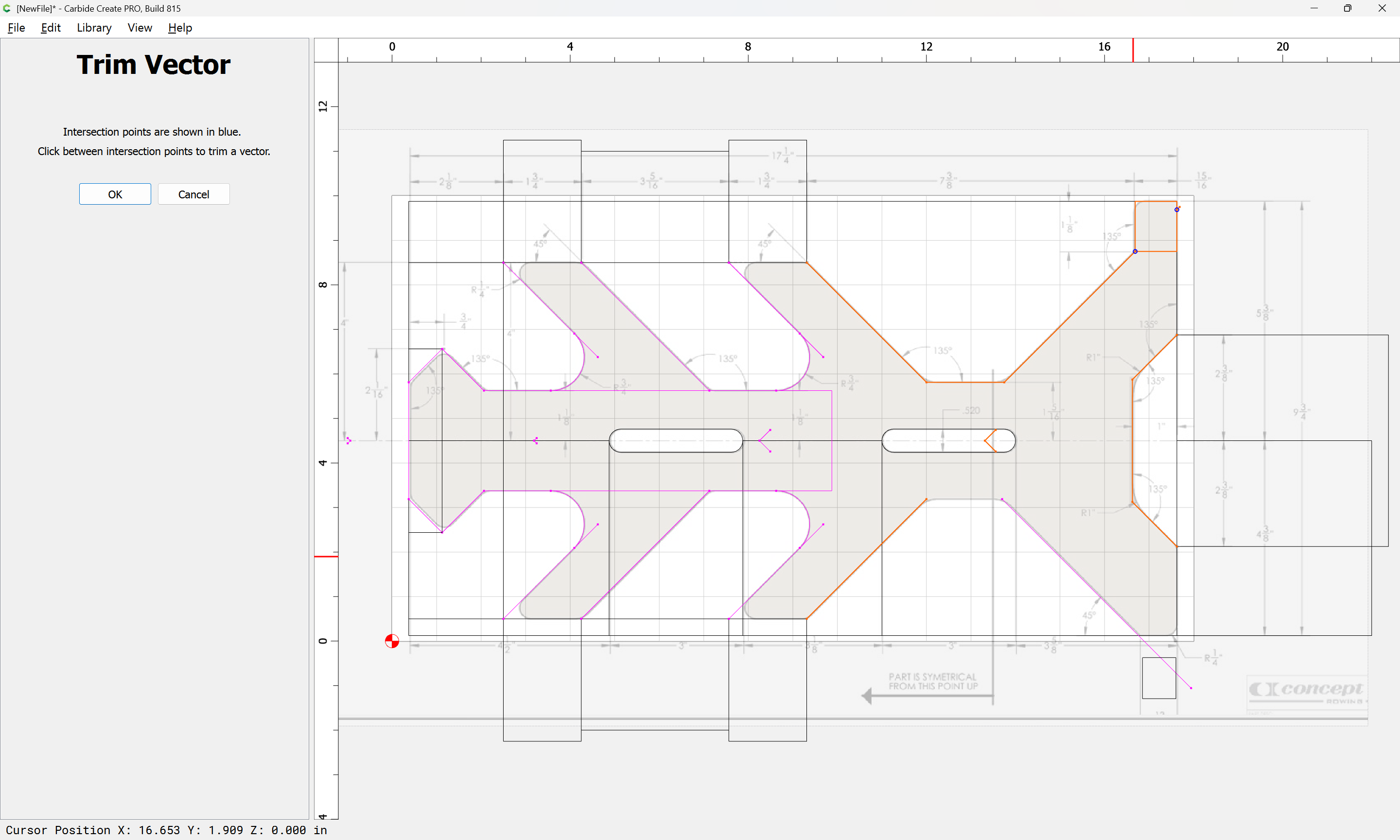
Draw geometry which will allow cutting it off:
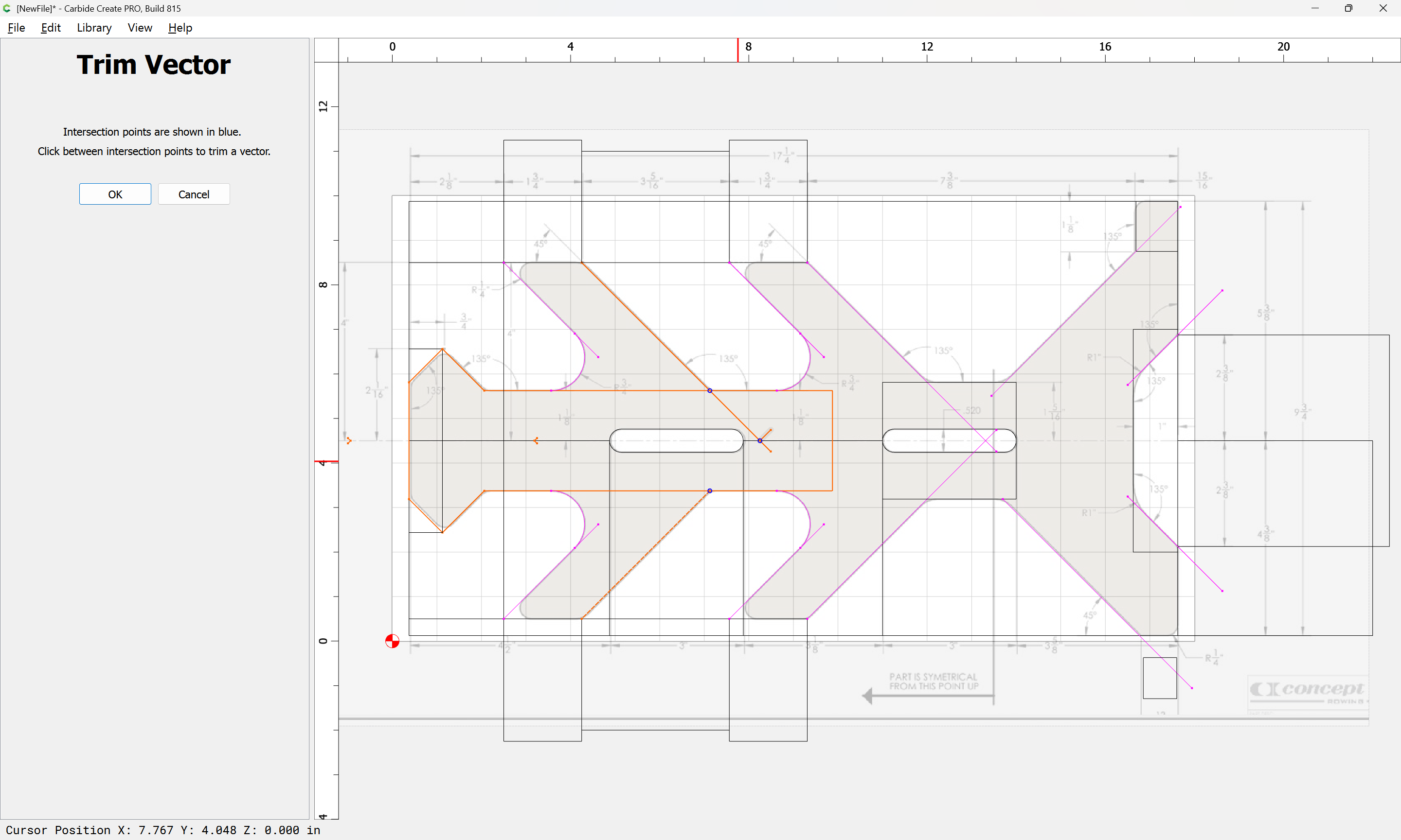
and use Trim Vectors to remove the excess:

OK

and delete the trimming geometry:

Duplicating what is needed as necessary:
i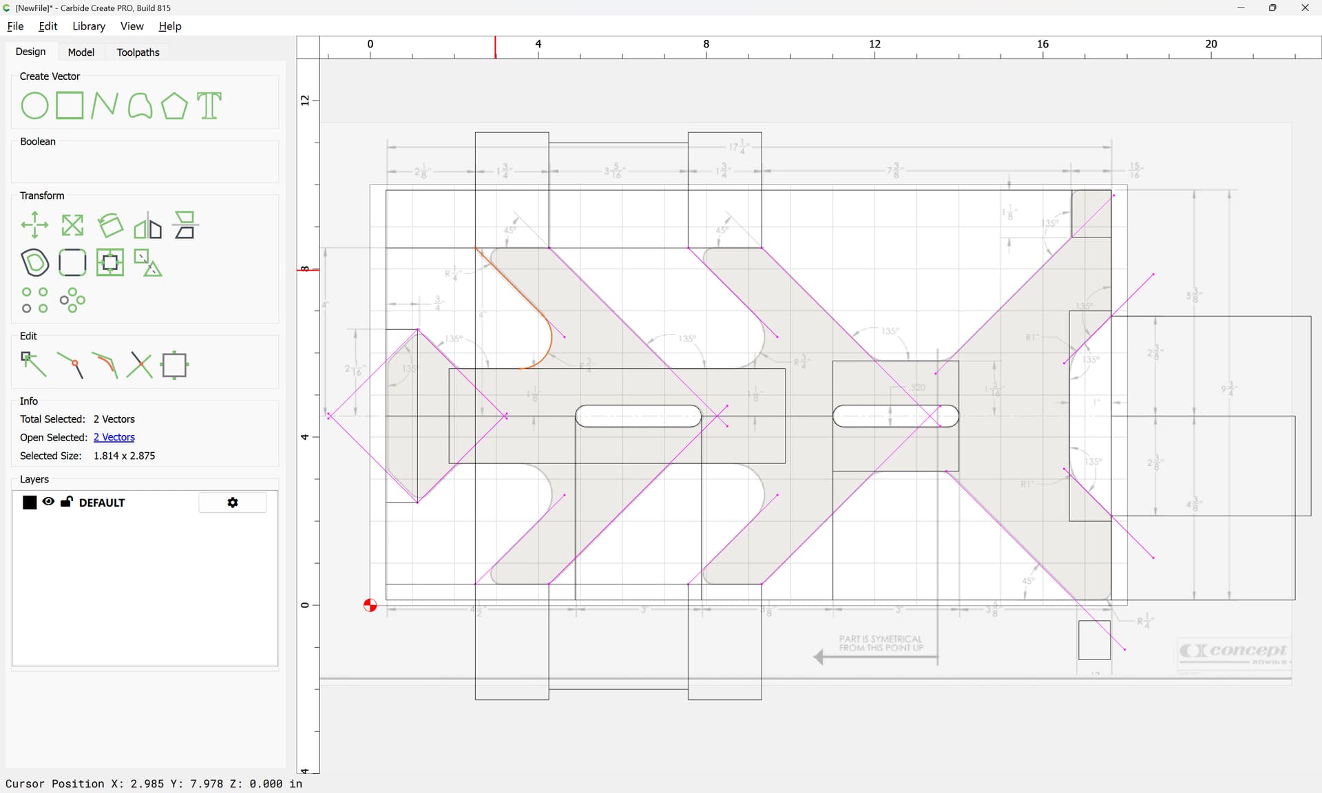

Mirroring at need:

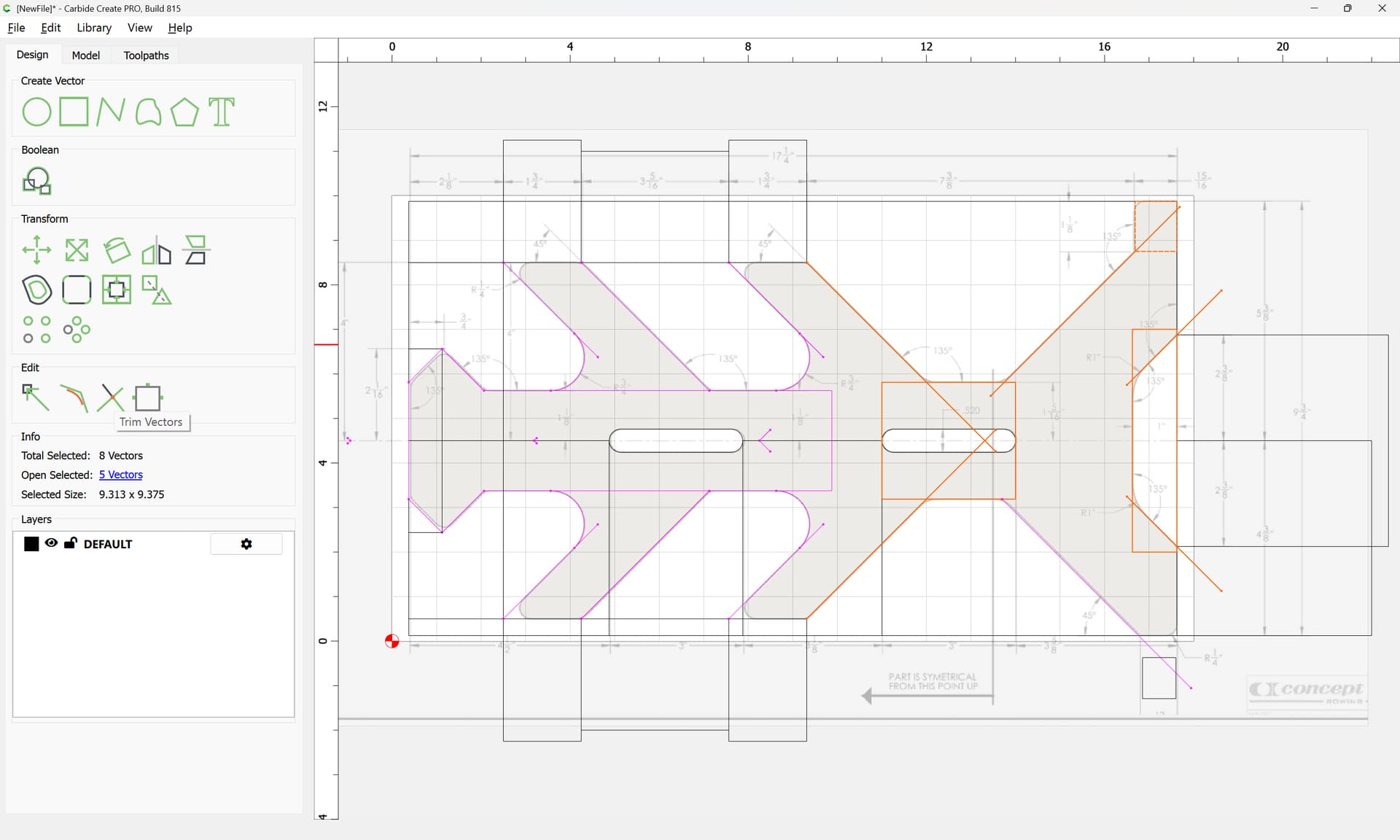
Where appropriate duplicate the geometry:
and use Trim Vectors to remove what is not wanted:


OK
Repeating as/where necessary:

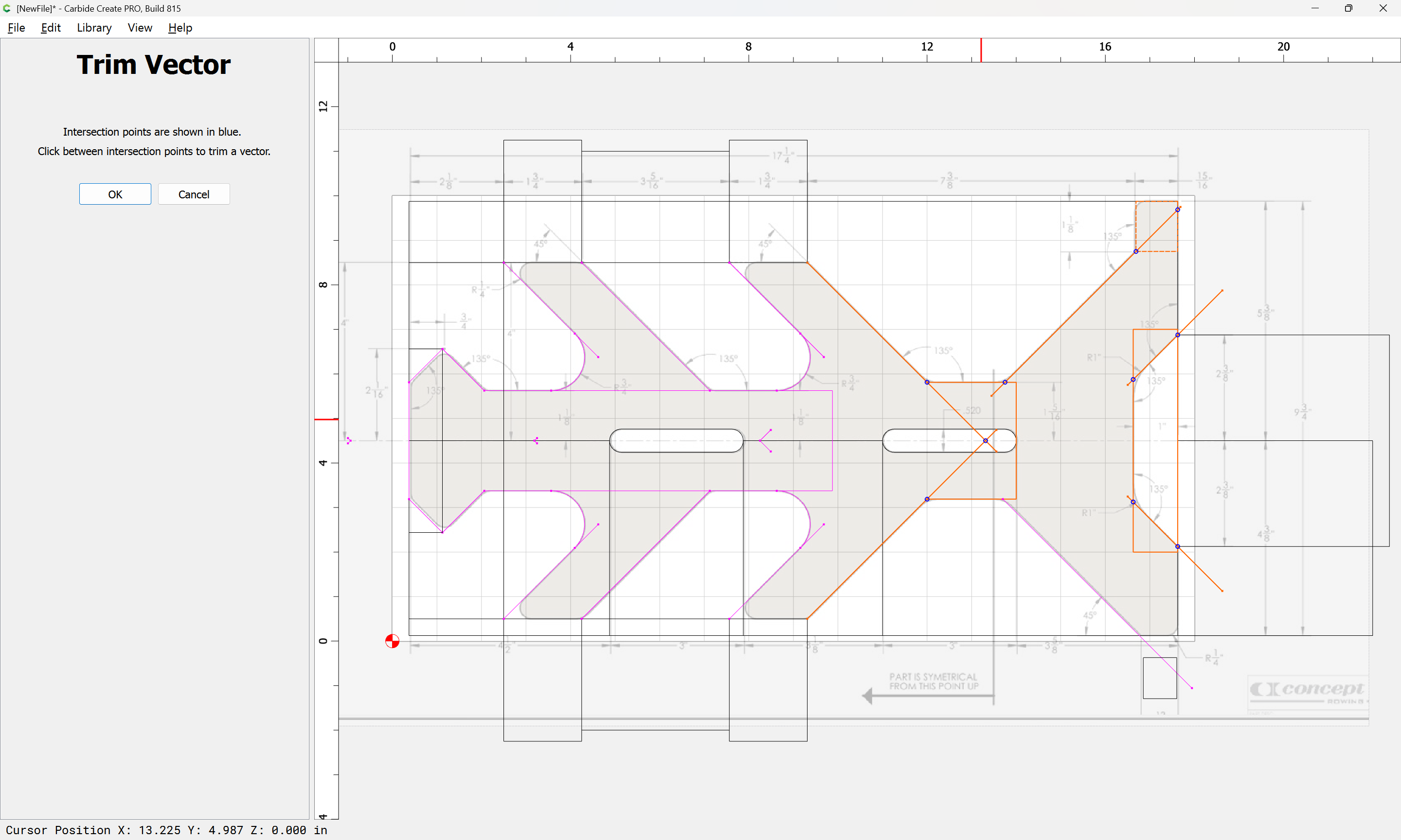

OK
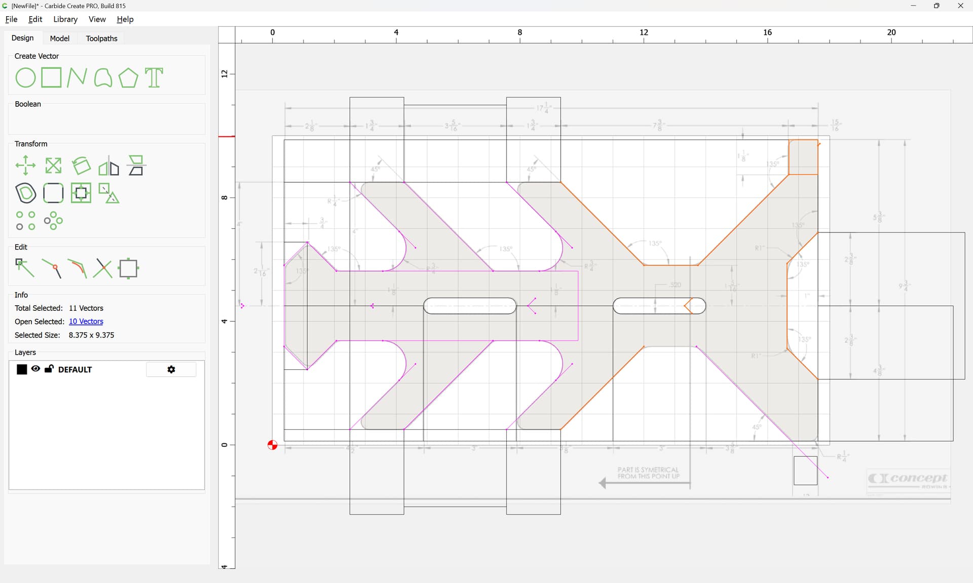
Delete redundant geometry:

and where parts were missed, address:

(note that the dimension for the lower right was cut off, so this may need to be adjusted)
OK
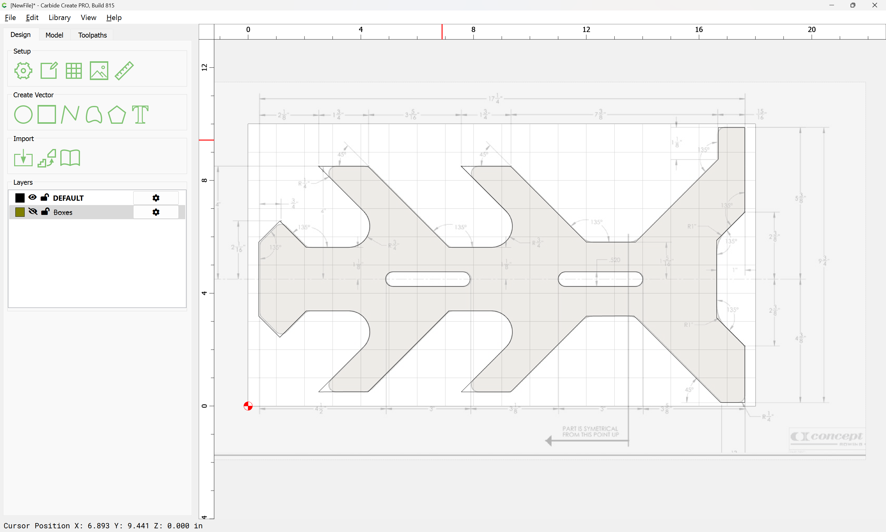
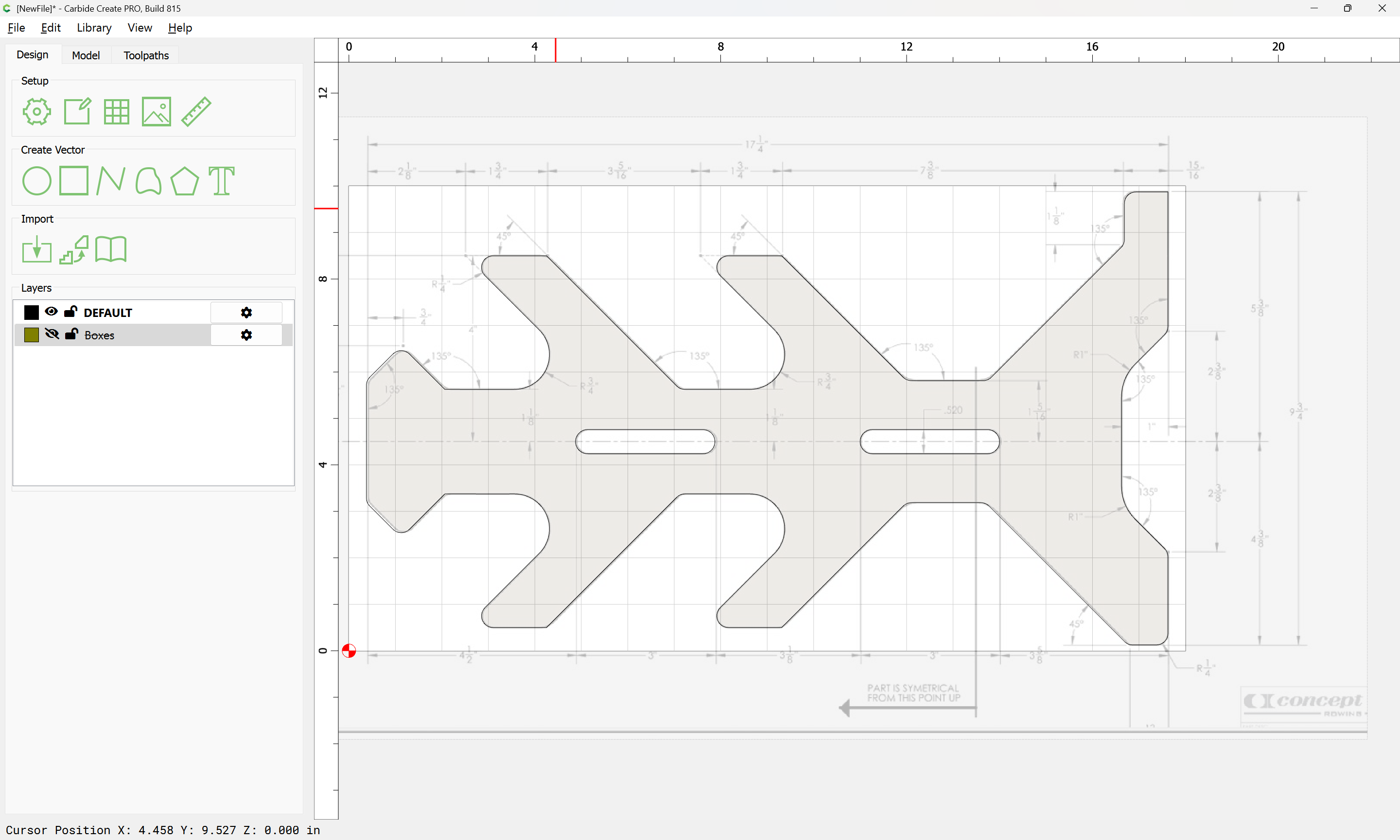
Select all measurement geometry:
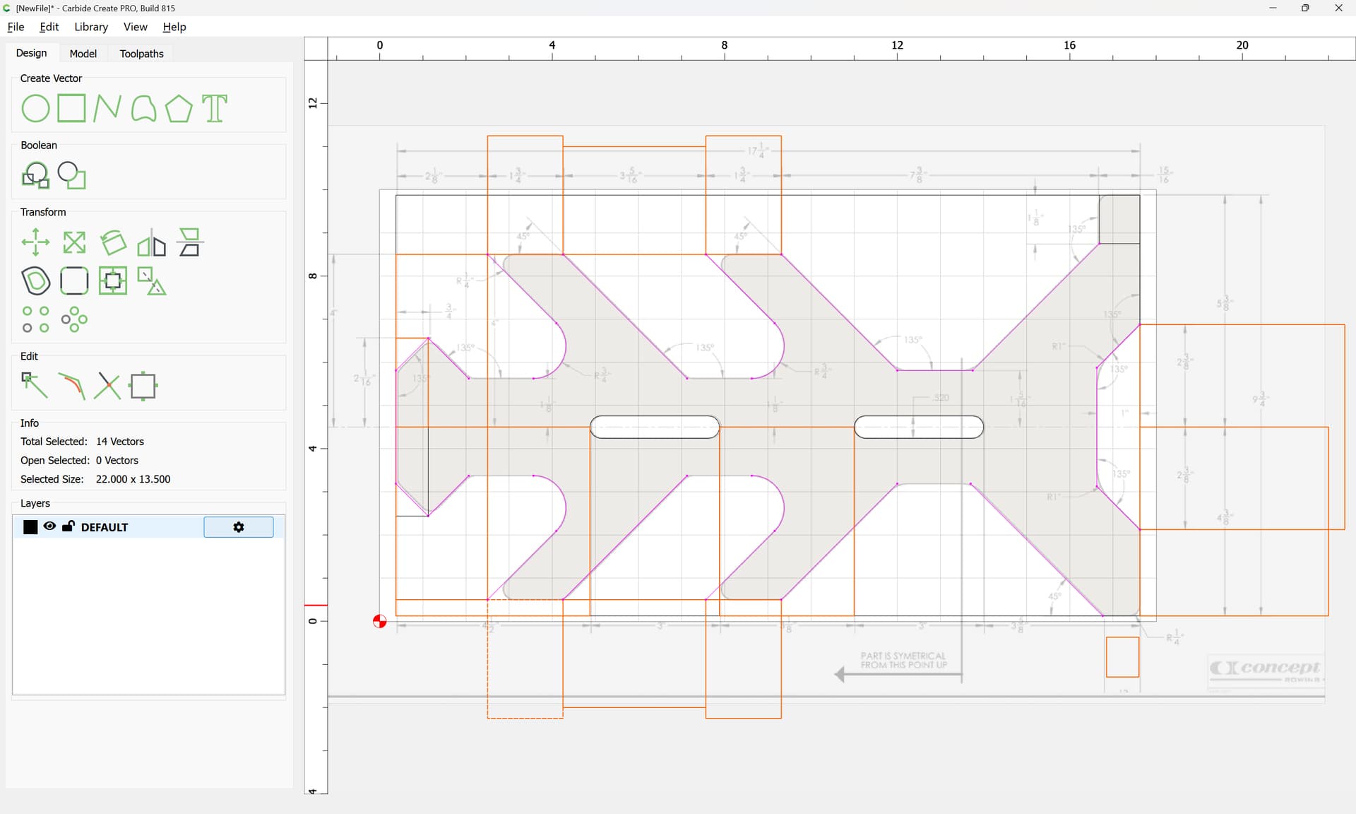
and send it to a separate layer:
d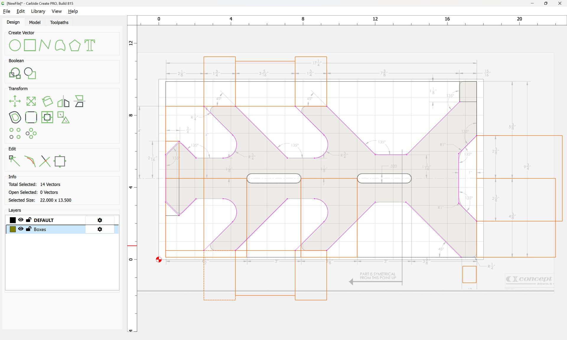
and hide
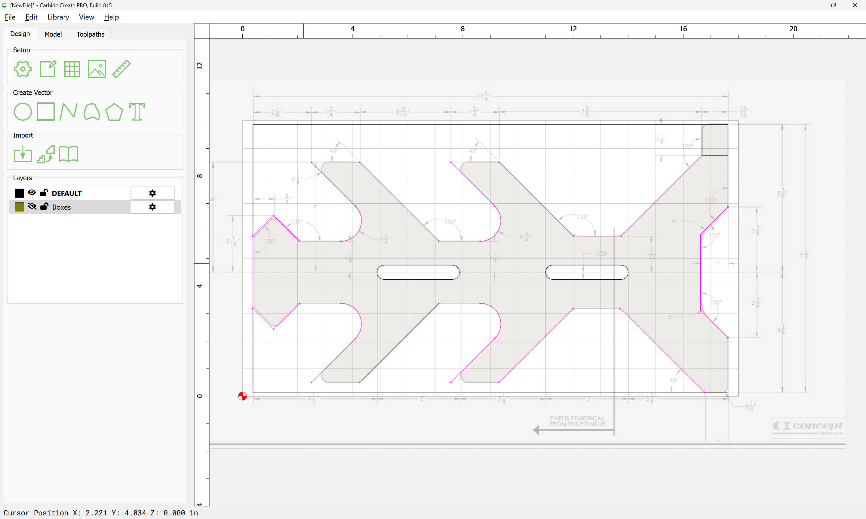
then connect the dots:

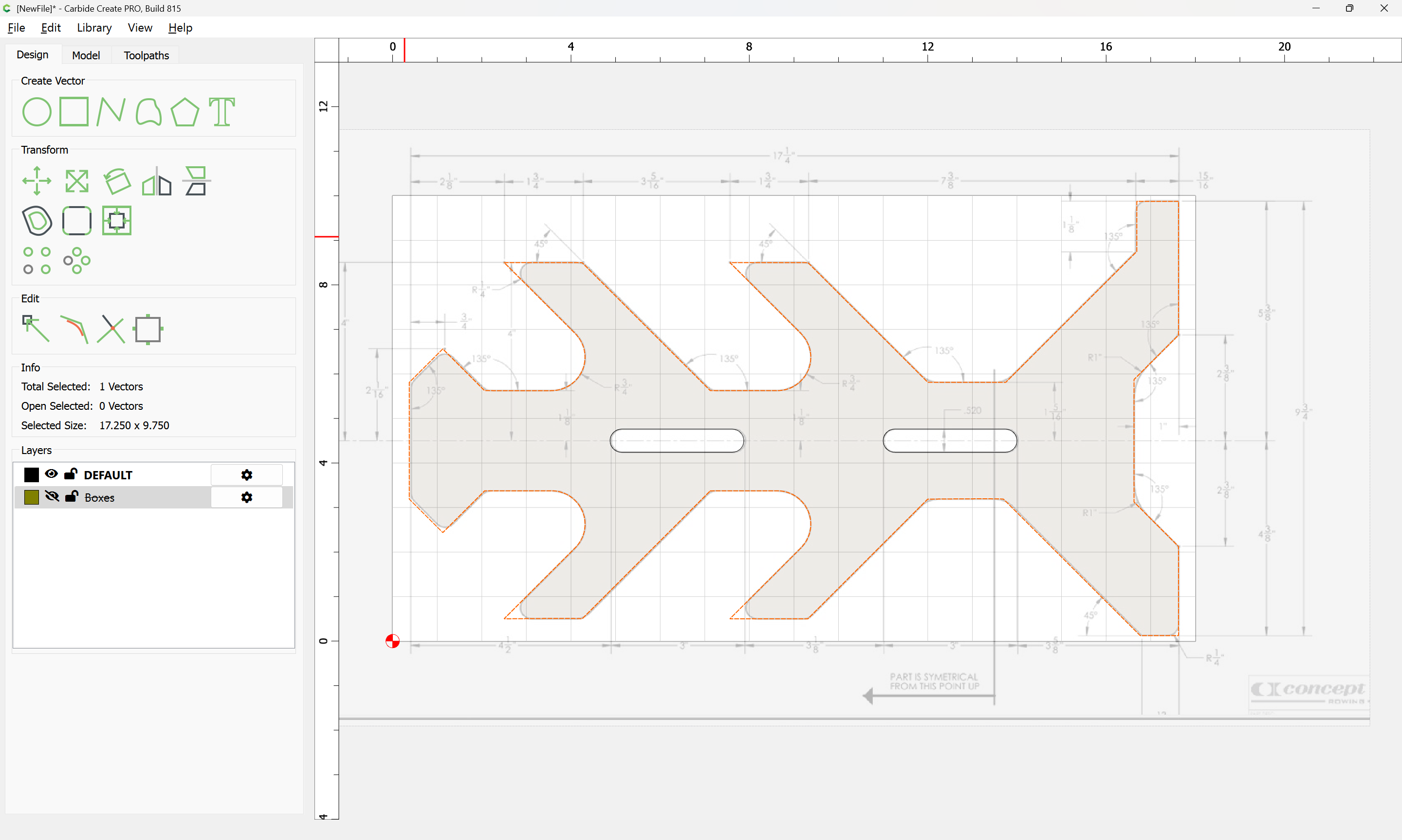
Select everything:
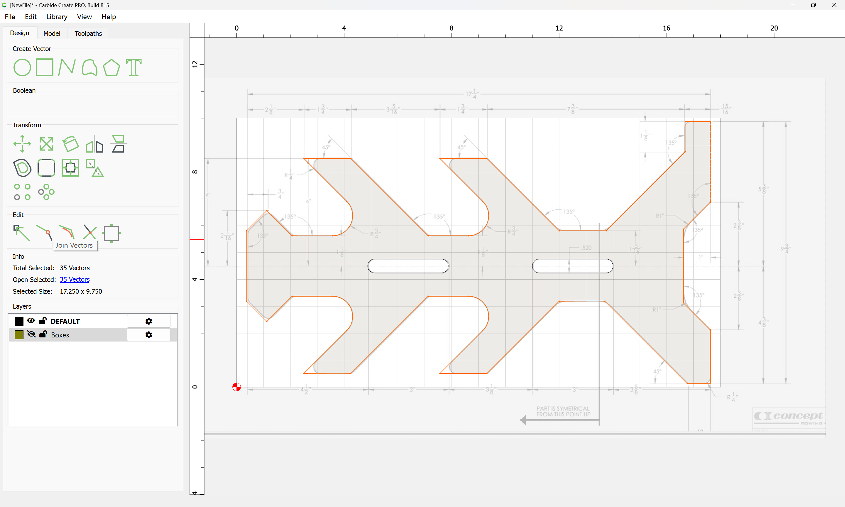
and Join Vectors:
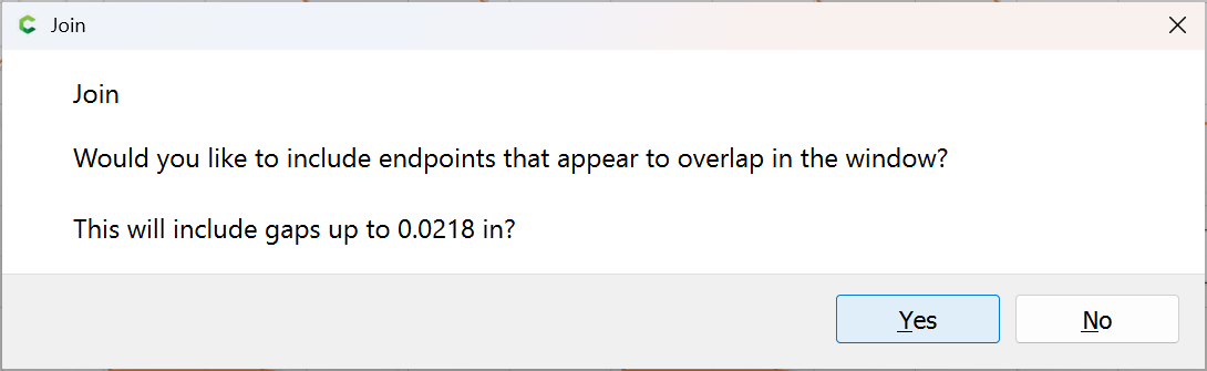
Yes
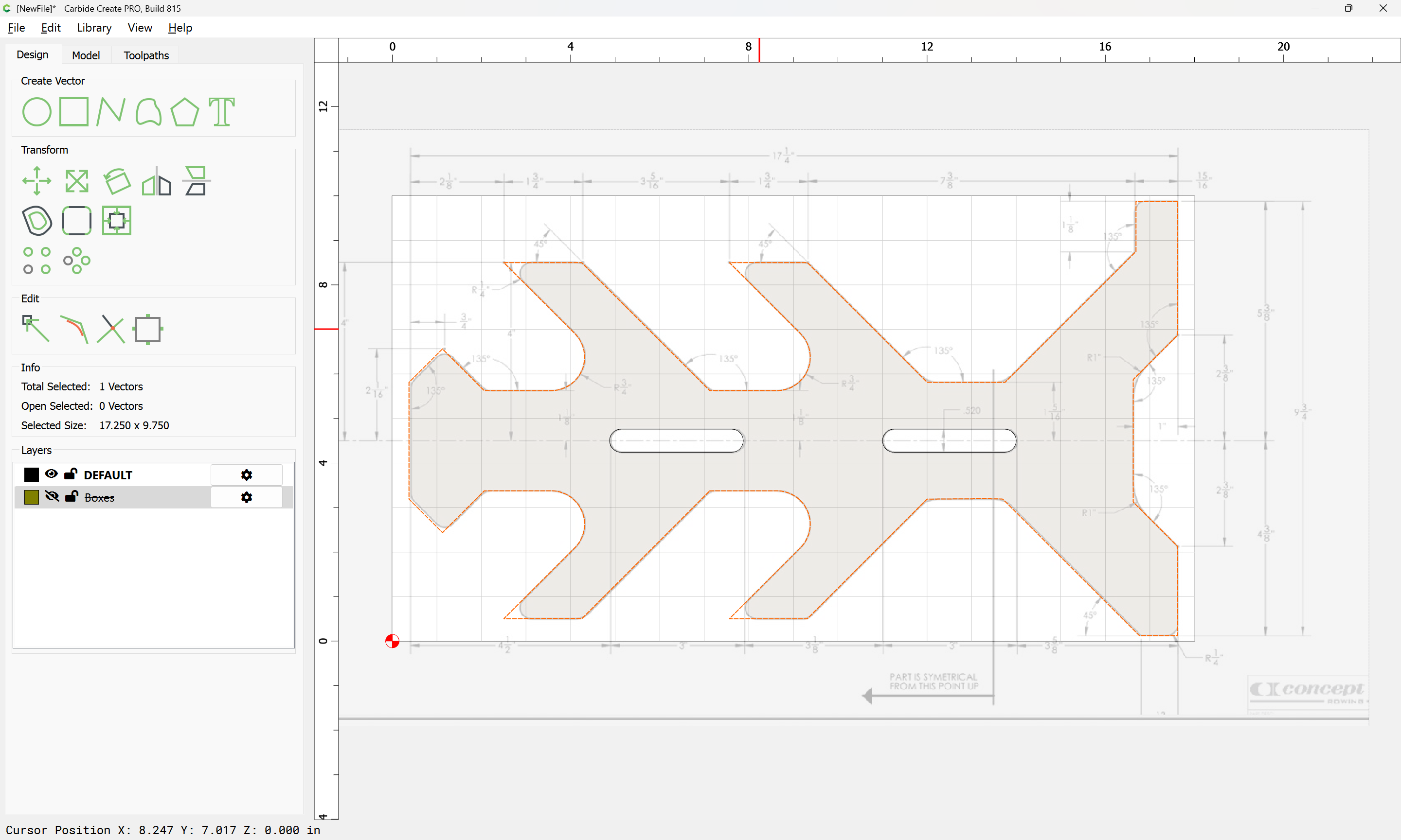
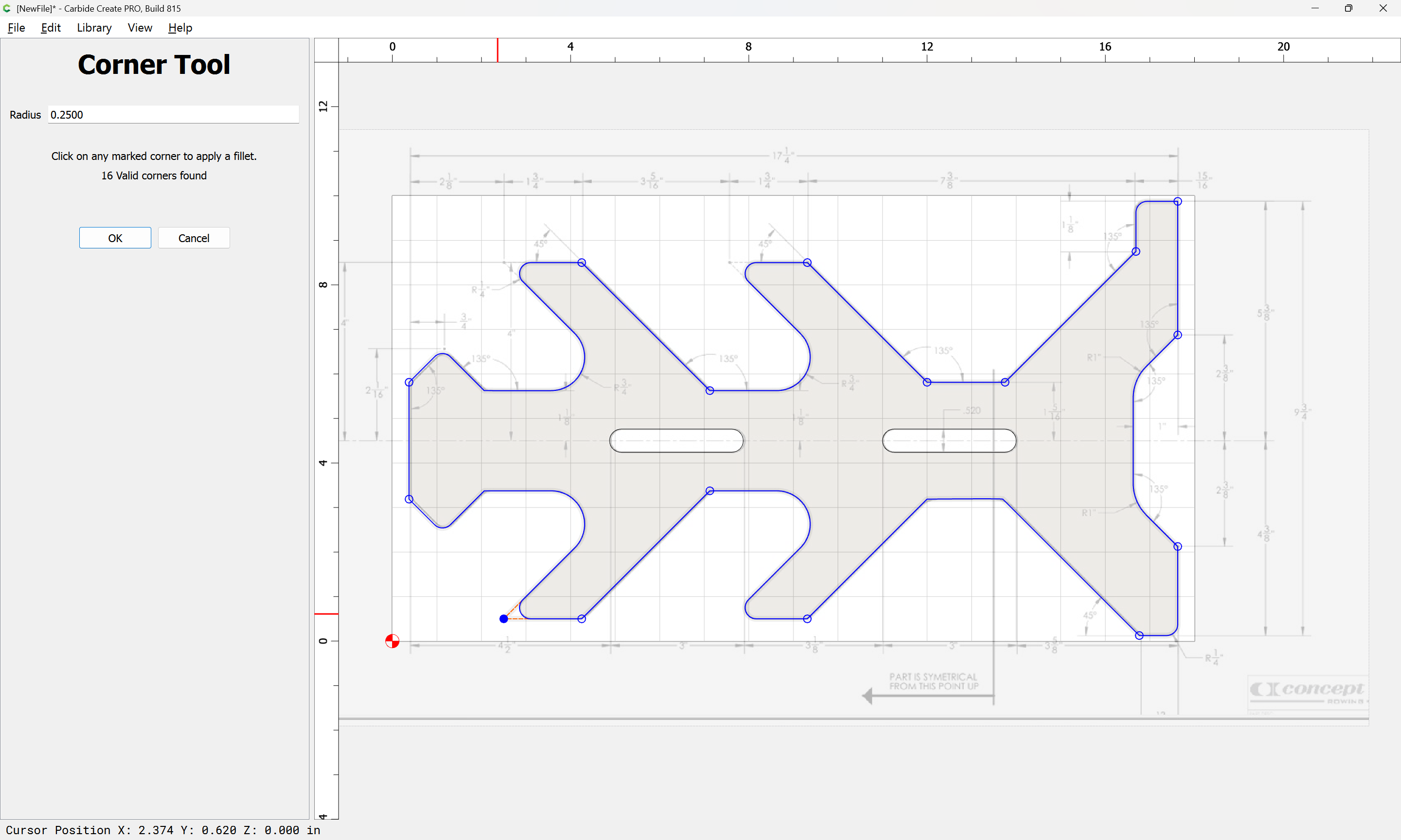
Select things:
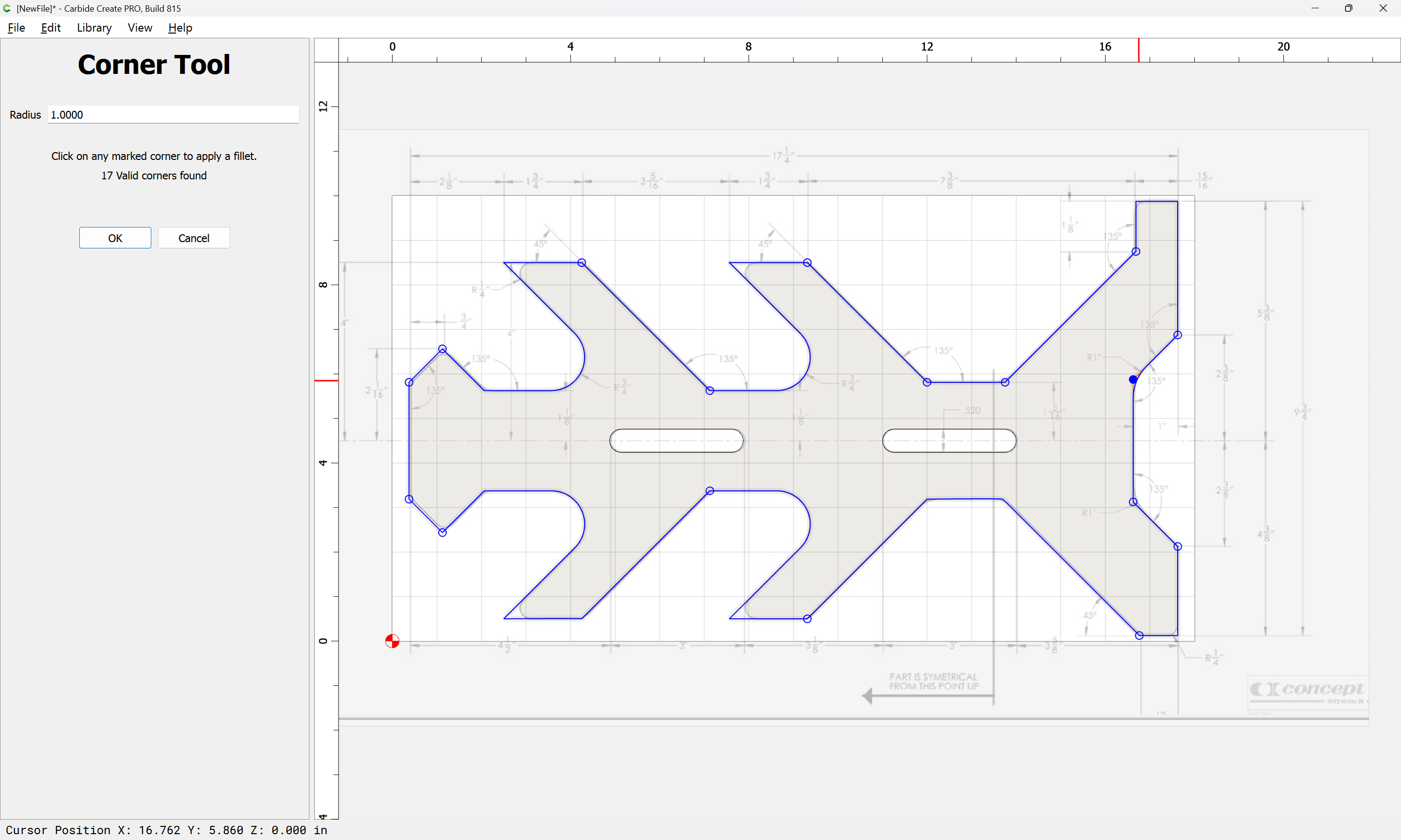
and use the Corner Tool:
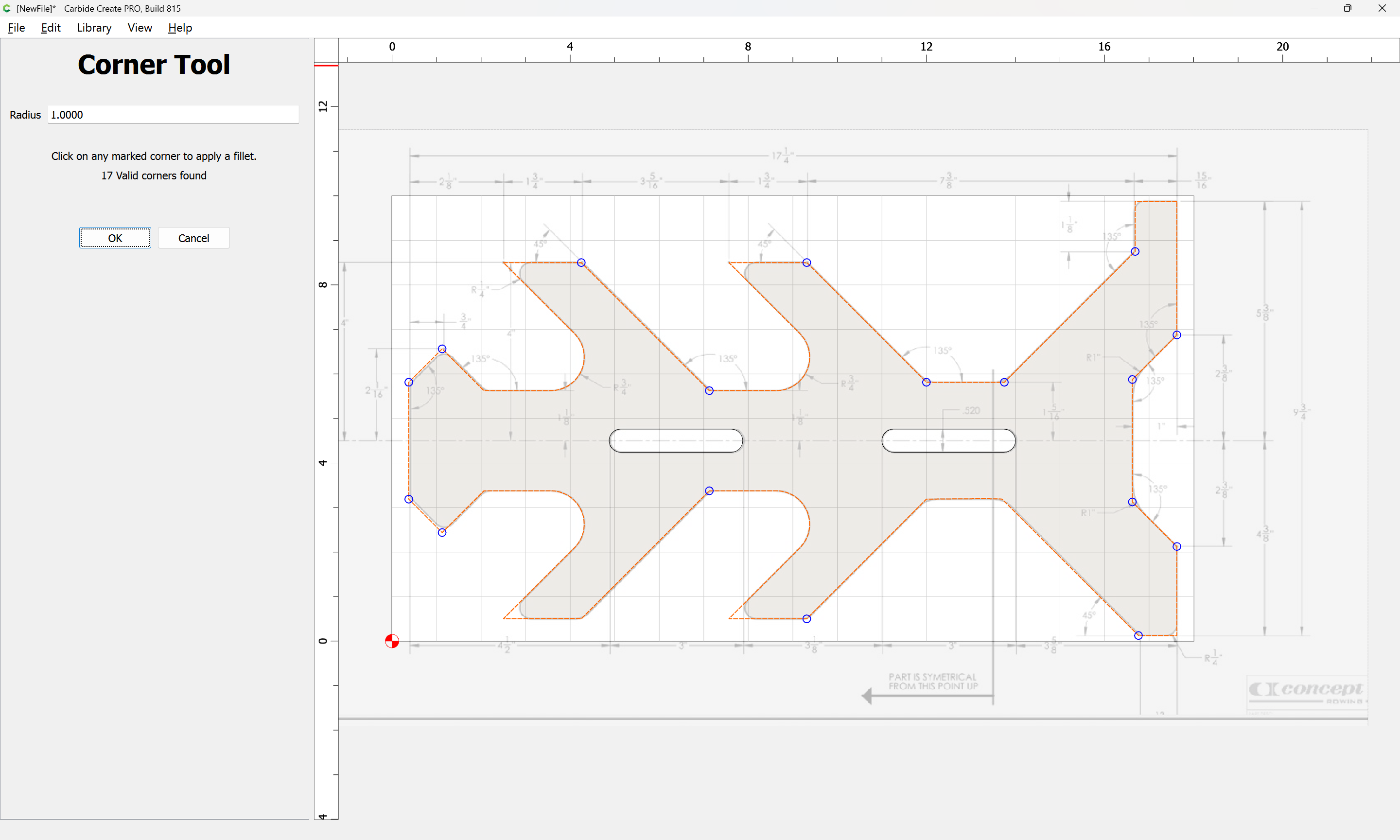
with appropiate settings to round off as needed:

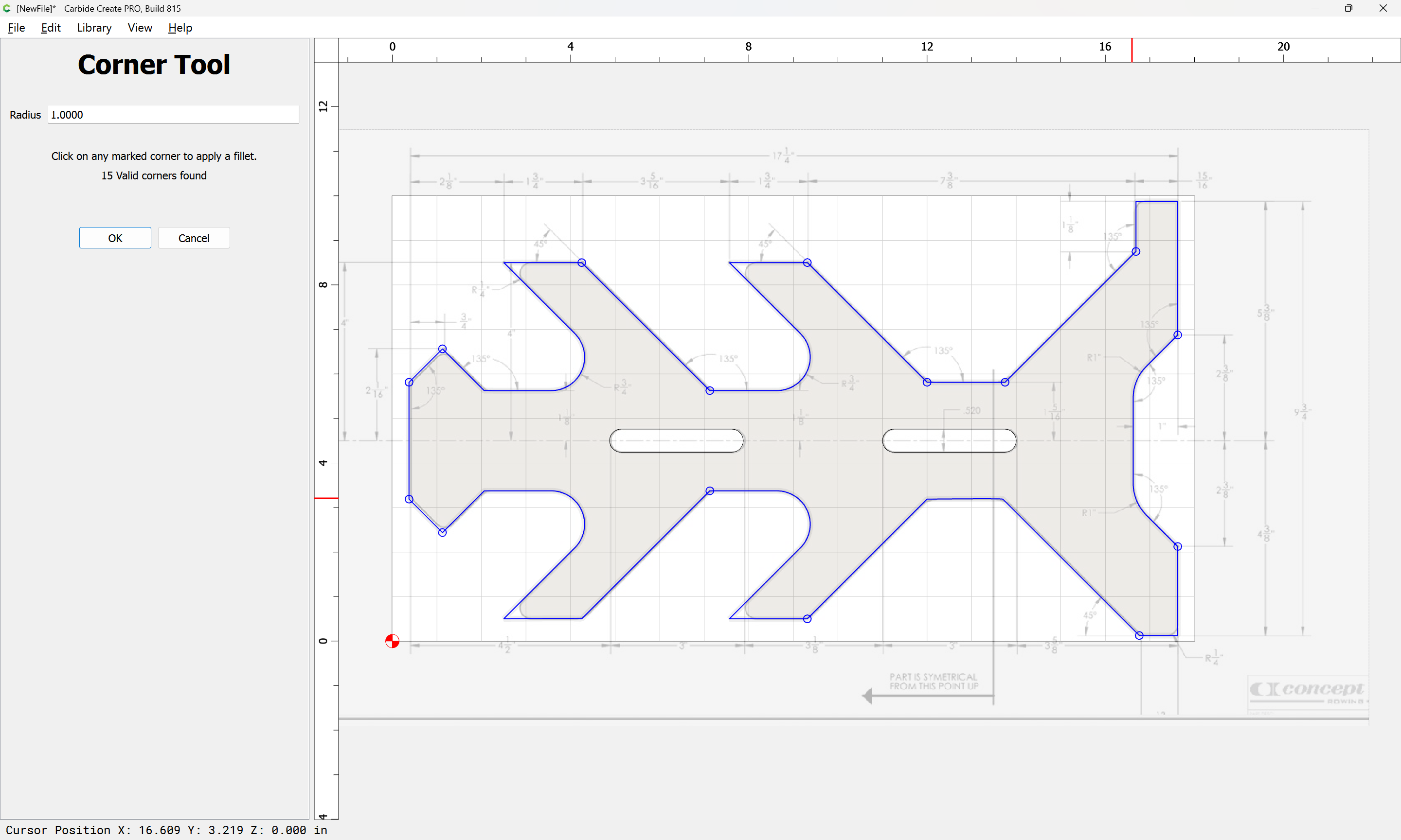
Adjusting the radius as necessary:


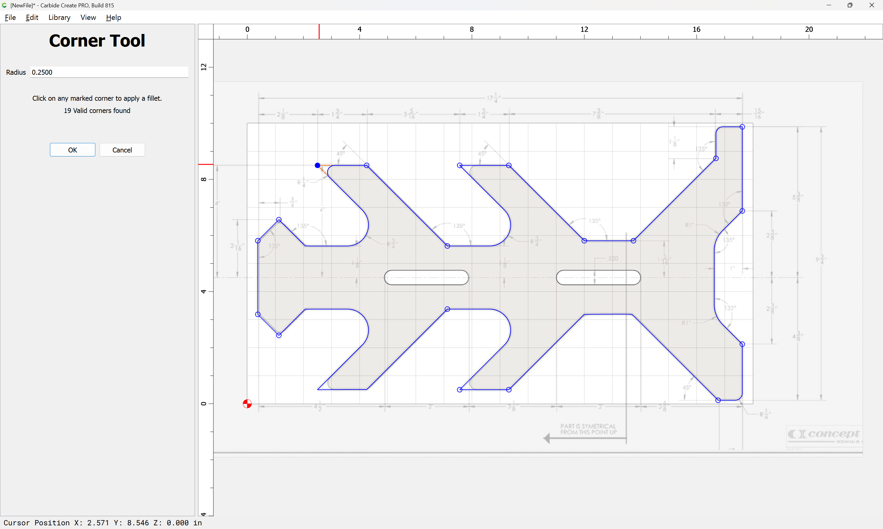
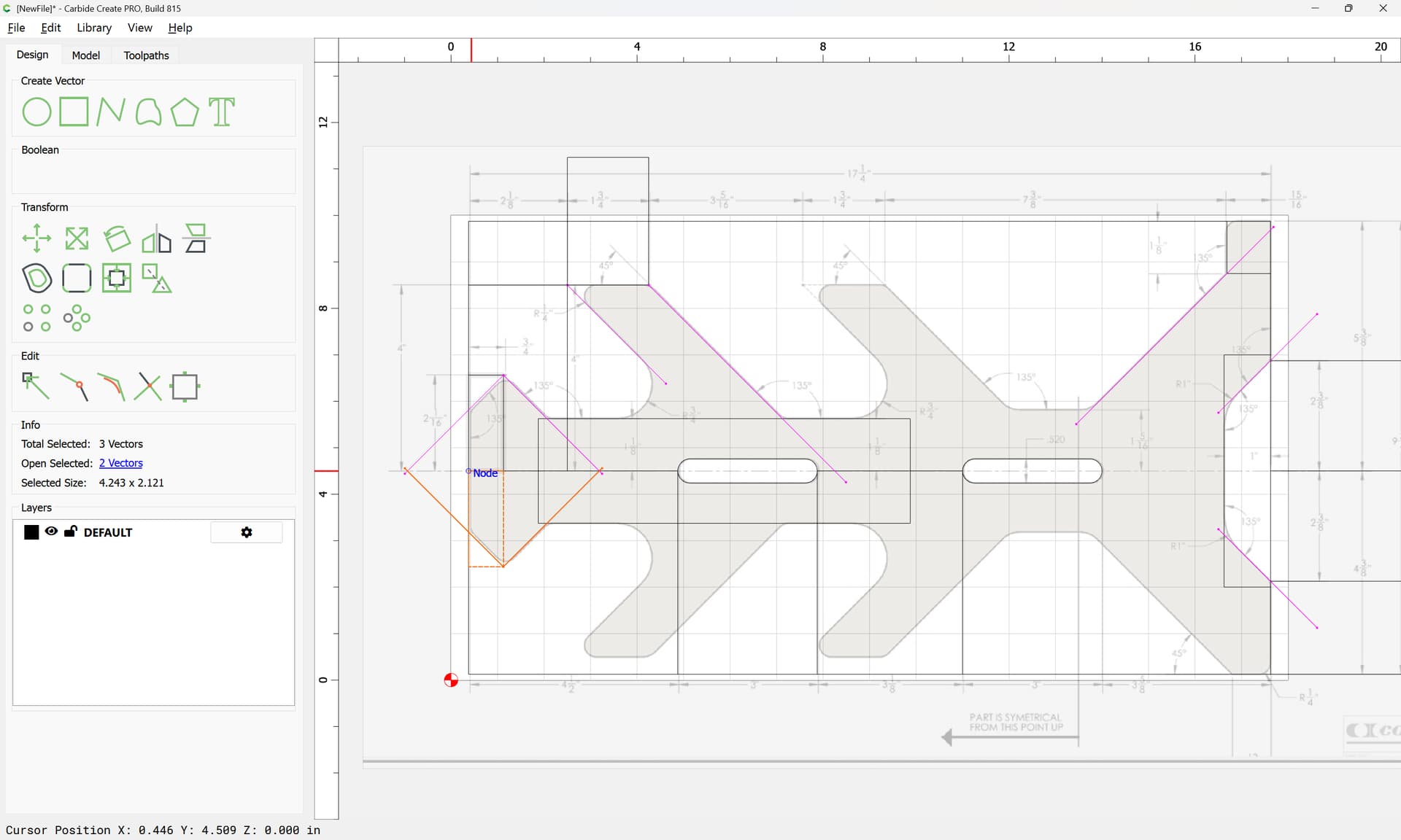
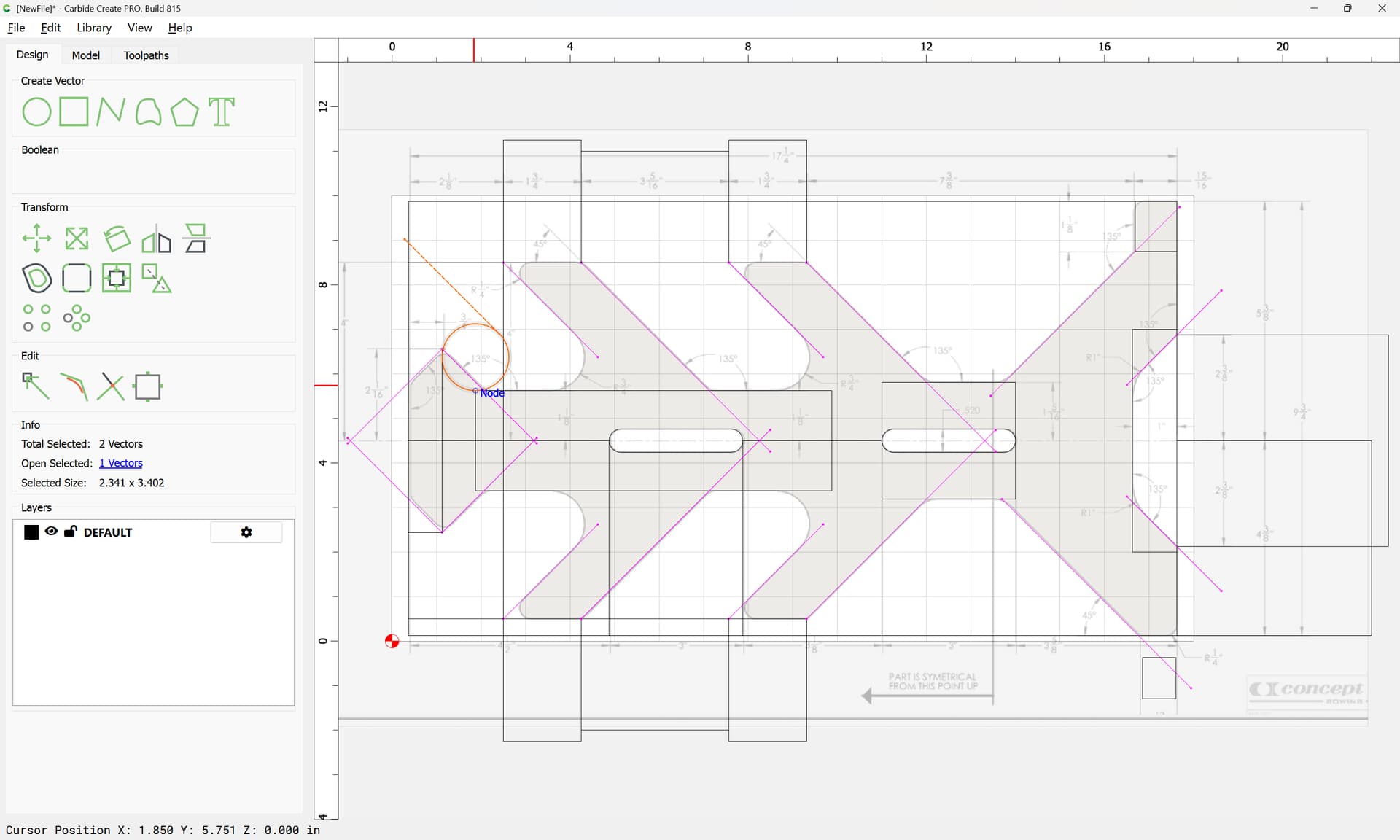
If a corner isn’t recognized as valid, go into Node Edit mode:

and ensure that lines are used to describe the surrounding geometry:
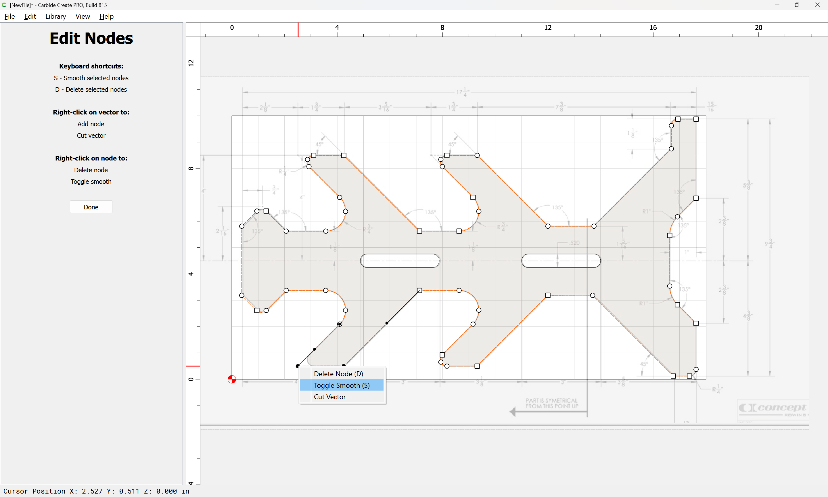
by toggling to Sharp Nodes:
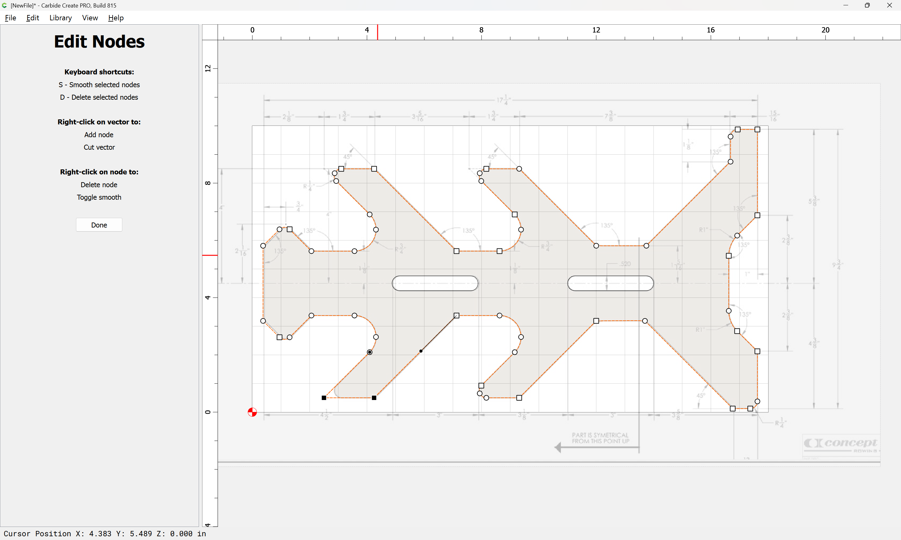
which will then allow the operation to work:
Attached as a v8 file.
oar holder_v8.c2d (288 KB)
2 Likes
Well, this is exactly what In tried to explain above… only WAY better!! Thanks Will!!
recommend a free 2D CAD-programm, I use QCAD pro (not free as pro), export it as dxf-file, and smoothly import it into CC.
I’ve tried such, and never gotten through the tutorial — LibreCAD is a fork of QCAD, try walking through that?
Will…you are a master! I have a lot to learn. I am stuck on the first step. How do you import as background? How did you convert the jpeg file?
never mind…i found it. Obviously missed the intro training.
Will, I think what to take does not matter. I started QCad, and added the Pro because it offers a CAM-Part with a simulation of the toolpath, what I found interesting before CC included that feature. However I did not find a way to import the GCode into CarbideMotion, so the free QCad works fine for me. It is possibly more versatile. However: if one is only HALF as proficient as you are with CC: no need for anything else.
(as OpenSourc also Inkscape can be used nicely, svg also can be imported seemlessly into CC, Gimp also can export paths)
Inkscape does not have a constraint solver.
It would be interesting if one was added to it as:
did to Blender.
inkscape has some path manipulation tools, that can be used to solve constraints. Always sucks… Same with QCad: always nightmare to solve them if they appear.
and Carbide Create has commands for moving and allows math input as shown above — not quite the same as a constraint solver.
FWIW, a more suitable CAD tool I would suggest folks try is of course:
for suitable projects.
Could not resist …
Parametric CAD is awesome.
BR
oarholder.dxf (5.4 KB)
Again, thanks for the education. Will…I took your design file to Cabide Create after adding the tool paths. I have the small Shakeoko Pro so i did have to make a small adjustment to fit it to the bed. I also flipped the orientation. In doing so apparently the cutout tool path did something unexpected. The outside right cut on the inside. It looks like the inside/left will cut on the outside. Did not see that coming…I assume this happened when I changed the orientation. Thoughts?
Oar Holder v2.c2d (60 KB)
You chose “Inside/Right”.
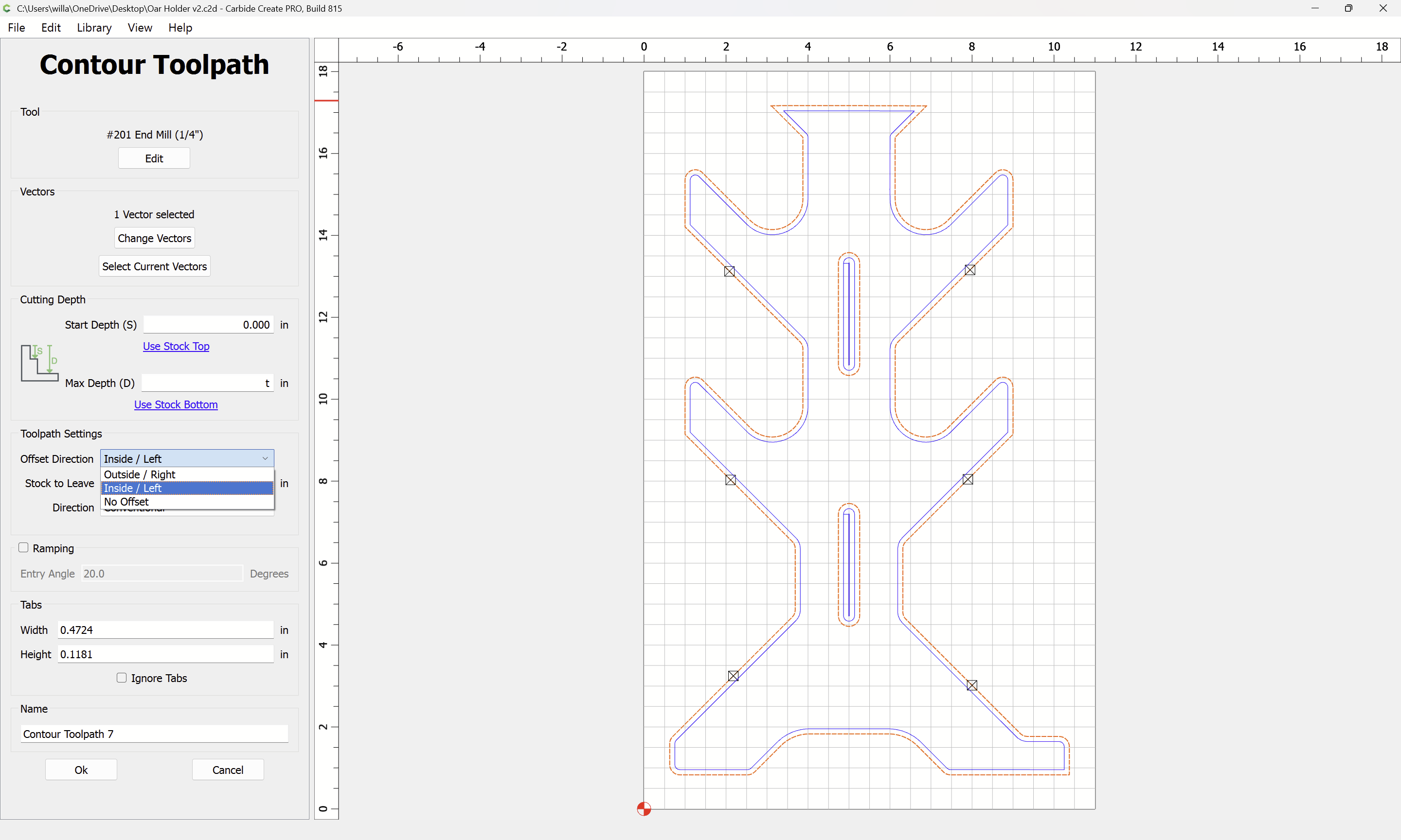
Try “Outside/Left”
That said, also offset by tool diameter plus 10% and cut as a pocket down to tab height:
Where possible avoid slotting and add geometry and cut as a pocket
and/or
and consider leaving a roughing clearance and taking a finishing pass.
inside/left works but seems counter intuitive. it must have something to do with the rotate.
…or the orientation.