Is it possible to implement rulers in CC to improve and speed up vector placement on complex designs?
This would be more user friendly than having to open the grid window, change the resolution and go back to count squares in the design. This is frustrating and a big waste of time.
I know this has already been requested in the past (2020) but it went unanswered.
1 Like
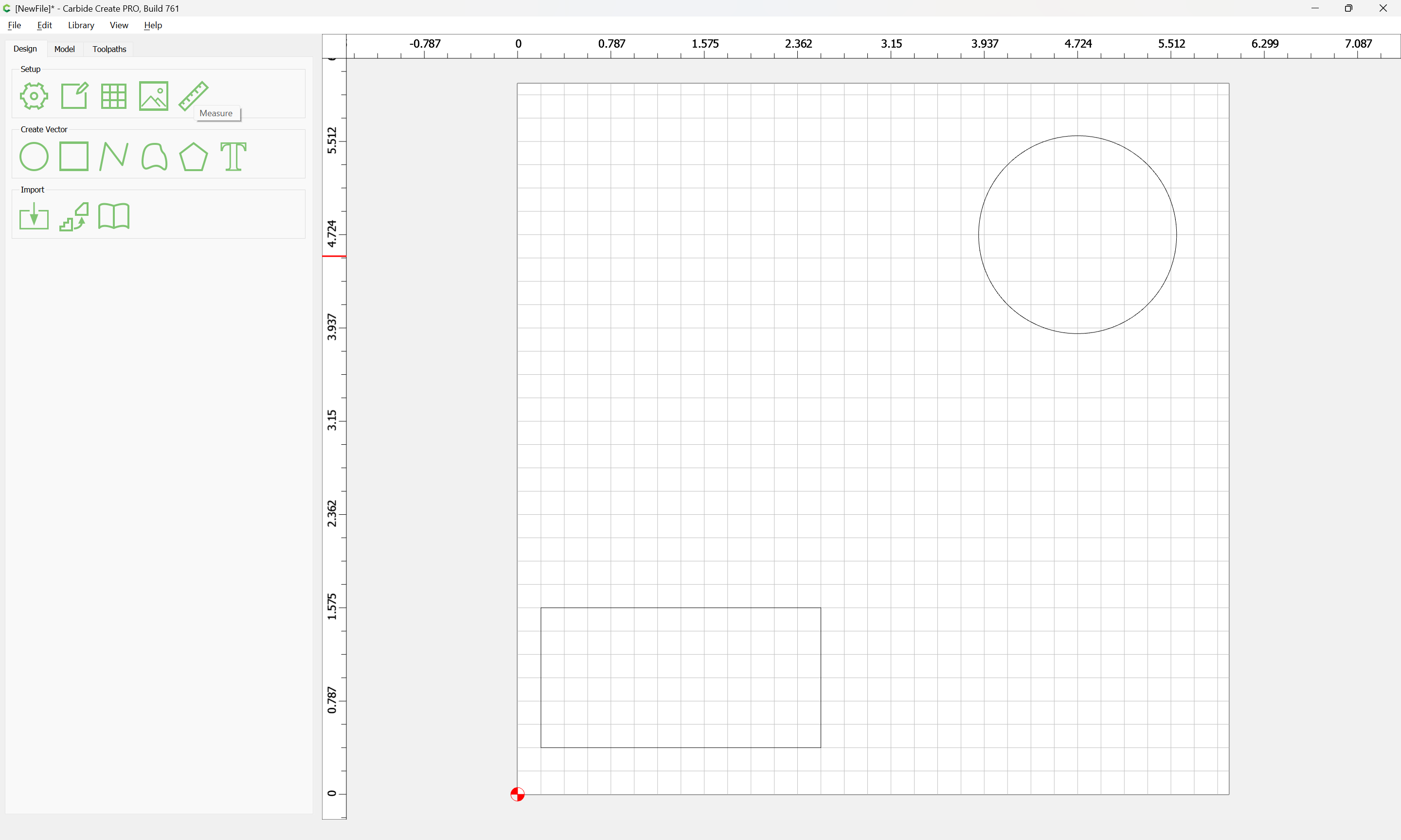
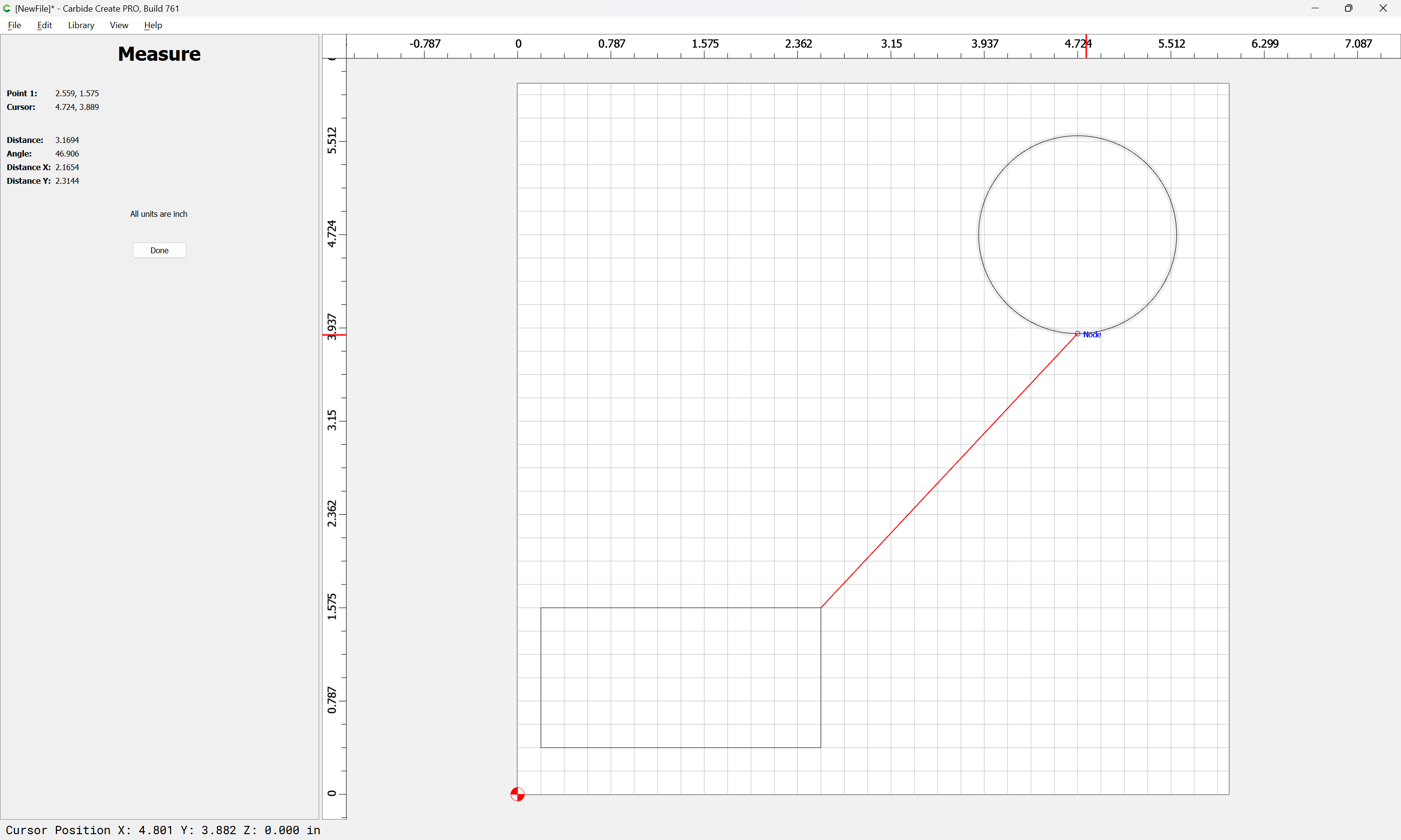
If you just want distance between points, there’s the Measure tool:
Speed should be much better in the new beta:
If you have a file which isn’t markedly easier to work with, let us know.
I understand that there are other ways of doing things, but they are less effective. It’s not just a question of distance between vectors… Moreover, the measuring tool is volatile and does not stay in place.
A ruler is a more powerful attractor than the grid itself, and moving a ruler with vectors stuck on it moves the vectors at the same time.
But maybe I’ve worked too much with MS Visio and I should learn to do without rules… But it’s sad and frustrating.
There are rulers around the perimeter of the window — how do those and the Measure tool not allow one to get the metrics desired?
Could you post a screengrab showing what you want?
I suspect you’re looking for is usually called a constraint system, and they’re more common in 3D CAD programs.
As much fun as that would be to take on, it’s not high on the priority list right now because it would be a massive amount of work to get correct, and would be of limited benefit to most of the files we get sent (which, admittedly, may or may not be representative of the average user).
1 Like
OIC.
As much as I would love for Carbide Create to have a full constraints sketcher, and as much as I wish I were successful at using the various opensource and other tools which have such features, the best I’ve managed at what I believe you are asking after was with Alibre Atom3D:
that said, I kind of crashed and burned in it when I wasn’t able to use the sketching tool in it for the better part of a year, apparently because I needed to delete the preferences file for the program (see the Alibre Forum for the details).
that said, other folks who are more patient and better at 3D user interfaces than I am do quite well in Alibre, so I feel quite comfortable recommending you at least give it a try if it suits your budget.
If you want a persistent thing for measuring in Carbide Create, ctrl-clicking w/ the rectangle tool will allow drawing from corner-to-corner — for complex projects I’ll often create a layer for such dimension measuring objects, hiding and showing it at need.
Can you share a use case or two? I’m struggling to imagine a case where a ruler would be necessary.
Although I’ve adapted to what is available. For example, if I want a line at an angle of specific length, I just make a horizontal (or vertical) line of that length, rotate to to the angle, then position it where I want.
The one case that’s stymied me is making a line or curve tangent to another curve. Unless they are prismatic/primitive shapes that can be done mathematically, it’s pretty much trial & error, move it as close as you can get it & then boolean or trim.
With circles & rectangles & polygons, you can type in the dimension.
Perhaps the same ability with lines would be cool, and a much smaller effort than full blown constraints.
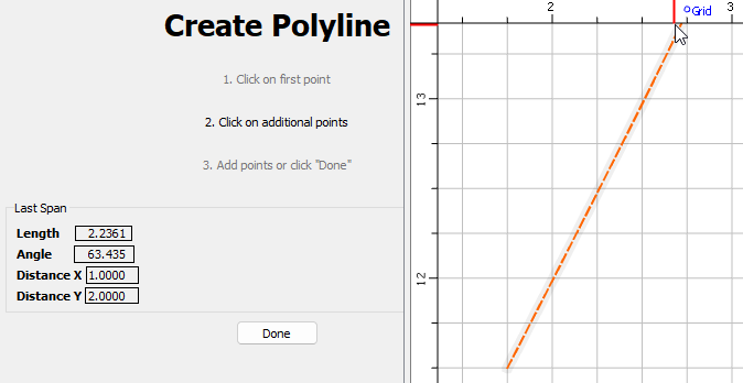
Enter Length, angle remains the same & XY update
Enter Angle, Length remains, XY update
Enter X, Y remains, Length & angle update
Enter Y, X remains, Length & angle update.
Enter Length & Angle, XY update & become gray
Enter Angle & X, Length & Y update & become grey
All parameters control the END point, the start point remains static.
1 Like
Yeah, we had two such discussions on this sort of thing before:
and
I think some sort of Minkowski/Hull function would be useful, but I’m drawing a blank at a useful descriptor or interface.
Hi, This is the 2D constraint system being used by a majority of CAD systems.
I have no idea of the licensing costs.
Not to down play CC, but I use Onshape for 2D work just for the above reasons.
Yeah, and a free alternative is the one used in Solvespace which is being packaged up for Blender:
Neither licensing option would be workable w/ our giving away a closed-source version of Carbide Create for free.
Another development in this space was:
(which I bought into at the $300 level, and after some initial experimentation and commentary gave up on 'cause the developer isn’t planning on doing the features I’d need until v3, if ever because his licensing agreement w/ the folks behind the CAD kernel which he licensed was that his program wouldn’t compete w/ normal CAD usage)
I considered using OnShape when it was first released, but kind of glad given their licensing kerfuffle — I suppose in its current state it would be workable for me (I upload everything I make to Cutrocket or Github or gitbook so that I don’t have to worry about backing up my computer), but the couple of times I’ve tried to go through their tutorials it never quite clicked, and every so often things would lag, which annoyed me.
1 Like
Good information as always, thanks.
I am a free Onshape user, all my documents are public, which is fine by me.
One thing that has caused me issues on occasion is after creating a square or rectangle of you rotate it then it no longer knows it’s a square anymore and you can not simply select and change the width/height.
It appears that even if you rotate it back to being normal to XY it doesn’t return that capability.
2 Likes
I see that my request is causing a lot of noise and that was not my intention.
I may have used the term “ruler” incorrectly.
I’m referring to a feature that allows you to set up a non-volatile “guide” on which vectors can be magnetized stronger than on the grid.
What guides can be moved and it takes with it the vectors that are “stuck” to it.
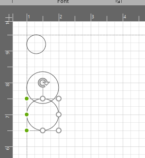
I paste a screenshot of MS Visio to clarify my point.
Either way, I don’t want to start a nuclear conflict on this subject. If it’s not feasible in CC’s current state, I can live with it. As stated in previous messages, there are several other ways to get out of this.
And of course, thank you all for your time in this conversation.
Oh, for that normally folks would just use the Align tool — not quite as interactive, but hopefully workable for your needs.
FWIW, that sort of auto-assistance drives me nuts and annoys me to no end so that I have to turn it off.
Another way to handle this is to just align the first item against a grid, then position the others using the grid.
Got it. I think those are usually called a “guide” in vector design programs. (Though Will can correct me)
It’s certainly a feature we consider from time to time. We just haven’t pulled the trigger on it yet.
2 Likes
Not noise, just a lively discussion. ![]() We’re all friends here, with a common goal: being successful with our machines.
We’re all friends here, with a common goal: being successful with our machines. ![]()
The picture didn’t make it clearer for me. It’s been a while since I’ve used Visio, and I imagine it’s changed quite a bit since. All the objects in your image seem to be aligned to the grid, so I don’t see “independent of the grid”. The nodes around the object being moved appear similar to the scale & rotate tool, in which nodes to snap to other nodes or grid intersections.
Is the “Guide” you mention the dashed line? I do remember visio wanting to align objects to other objects in nice neat rows & columns, and needing to disable that feature to avoid it.
As Will mentioned, things wanting to automatically snap is sometimes tedious. I do find myself turning grid snap off, and wishing I could turn node snap off in CC. So I have to zoom in to avoid the node snap. But it’s cool when I do want to use it.
Specific use cases would really be helpful, especially since everyone is not as familiar with the feature in other software.
3 Likes
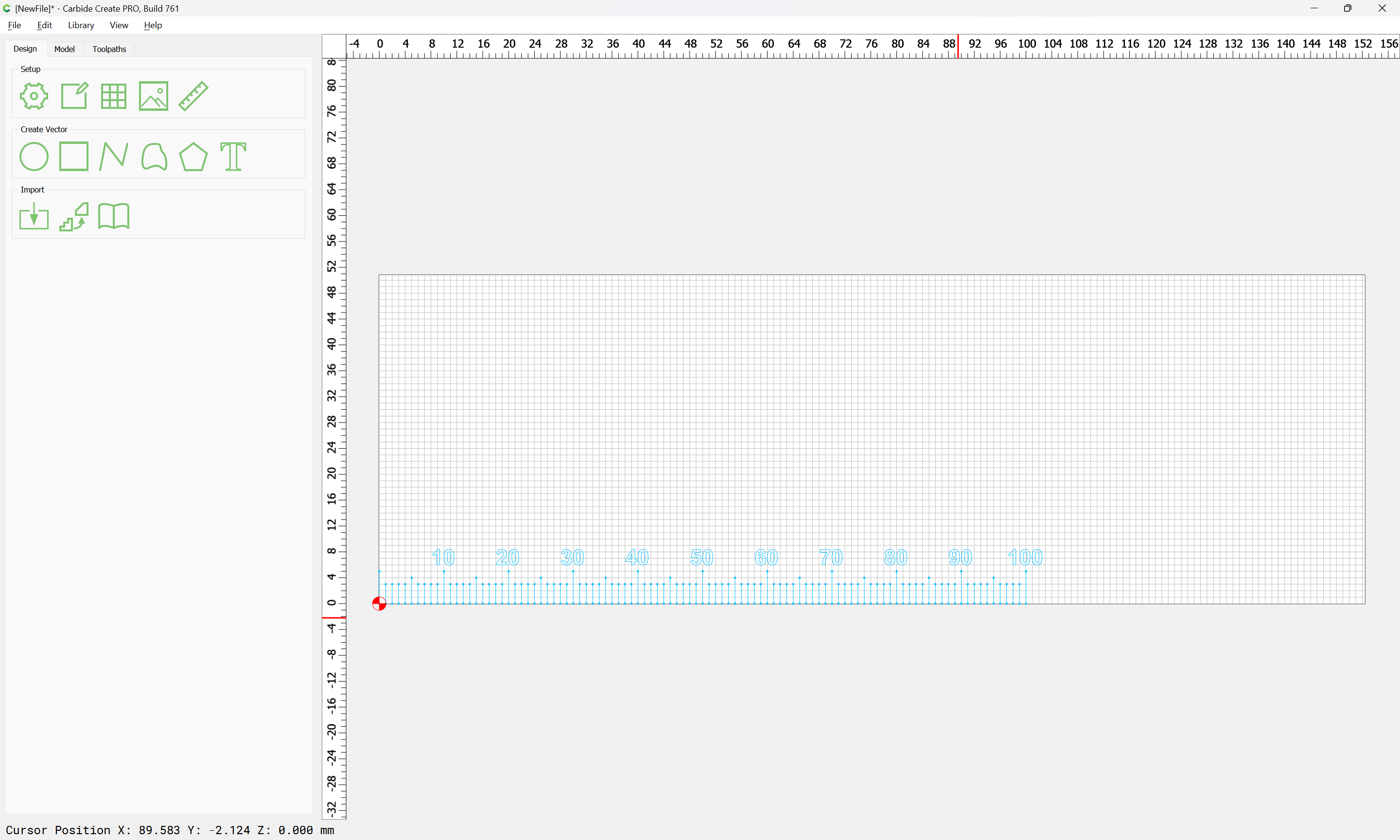
I frequently use ArcGIS (a geographical information system) and I think what you’re referring to are called “guidelines” in that context. I’ve often wished CC had these. They don’t need to be complex. For example, just clicking on the “4” on the vertical ruler would create a straight (let’s say blue) horizontal line across the grid. Makes it super easy to line up other polygons (vs. having to count 1/4" squares in the grid). Clicking back on the 4 would turn it off. It has no impact on the toolpaths.
1 Like
In Adobe Illustrator and InDesign I believe they are called “Intelligent Guides”.
As noted, I mostly turn them off — if I want something aligned, that’s what the Align pallet is for.
This topic was automatically closed after 30 days. New replies are no longer allowed.