I have been on a 10+ day quest to figure out the Shapeoko Pro base frame bolt down spacing!
I messaged @wmoy, I emailed support and was told 320mm give or take 5 or 6 mm, which was very frustrating lol.
I ordered a few different metric rulers and meter sticks, and have found it is very hard to get an accurate measurement trying to find center on countersunk and threaded holes.
After endless adjustments and best guessing, I believe it is 322mm distance between slat bolt down holes with a 105mm wide bolt pattern.
A mistake will likely cost me about 500 dollars and waste 60+ days to get replacement extrusions cut, I keep coming up with 322.4 mm and it has been making me hesitate, they would not use some weird spacing like that right lol. Not a huge deal but x4 the offset will make my access holes not line up and my support brackets will not fit also.
Could someone suggest who at Carbide 3D I might try to contact to take a quick look at the Pro model and tell me what the actual bolt down spacing is?
If the holes are the same size, you measure this from one edge to the same edge on the other hole, rather than the centre of the hole. It’s much easier. If you need to offset from one edge, add half the M? size for the metric bolt.
I wonder if you could put the cross beams (what you have as short lengths) of your extrusion as single pieces, uncut, underneath your longer (1005mm) beams?
Then you can use T-slot corner connectors to slide the longer elements into place, meaning that you won’t need to cut those 322.4mm bits at all.
My issues with that include what spot on top of the hole the threads start on, and it being metric, using a stick it is hard to discern exact edge locations looking down, I was taking a razor blade and trying to center it on the metric marker lines, having the point on center, tried eyeballing center with tape etc, all methods are just not exact, hard to say if i’m off or not and it just never seems exact on 322 mm.
I think if you change your design just a little, by not doing right angle joins of the small sections in the Y axis, you will end up with one where every fixed point is “slideable” in X or Y and can be locked in place with connectors.
Therefore, you won’t need to worry about measurements since you can use t-slot nuts for these particular holes.
The t-slot connectors are pretty hard to move once tightened.
If you are unsure, just drill a hole into the extrusion after you have sat the machine on the bed?
By making the longer extrusions slide over the single central one, rather than intersect it, you get rid of the spacing problem, and I daresay it would be stronger too.
EDIT: If you are worried about the single horizontal piece slipping down, use 4020 (or whatever size it is) for the base section, so you have two horizontal slots to secure the horizontals at two different heights.
I will consider that, it was my intention to have locating holes attaching the sides of the 322mm 80/20 slats with double counter bores, and vertical access holes on the 322mm horizontal slats for the frame to bolt it down without drop in’s/slide in’s so I can use bolts with washers. Front to back was more for structural and squaring.
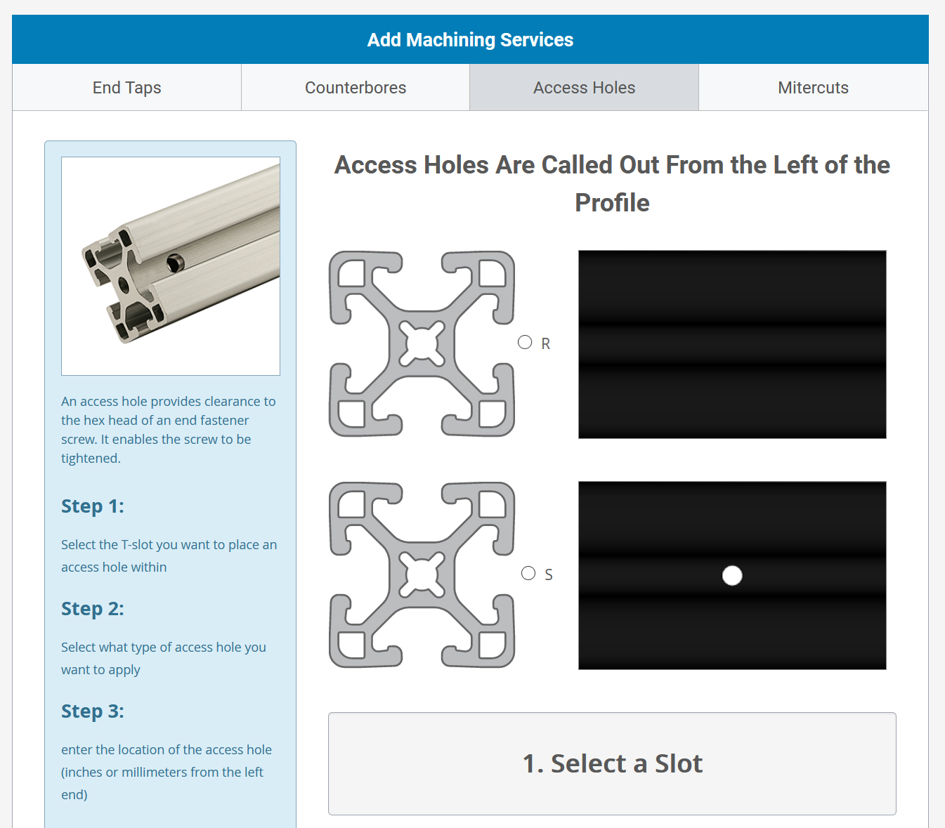
I can order a access hole jig. https://8020.net/6075.html
Still a big pain in the ass haha when I can pay them a dollar a hole. But it would be nice to have the actual measurements, since the machine does have bolt down holes and it would benefit a lot of people to have access to those basic dimensions I am sure.
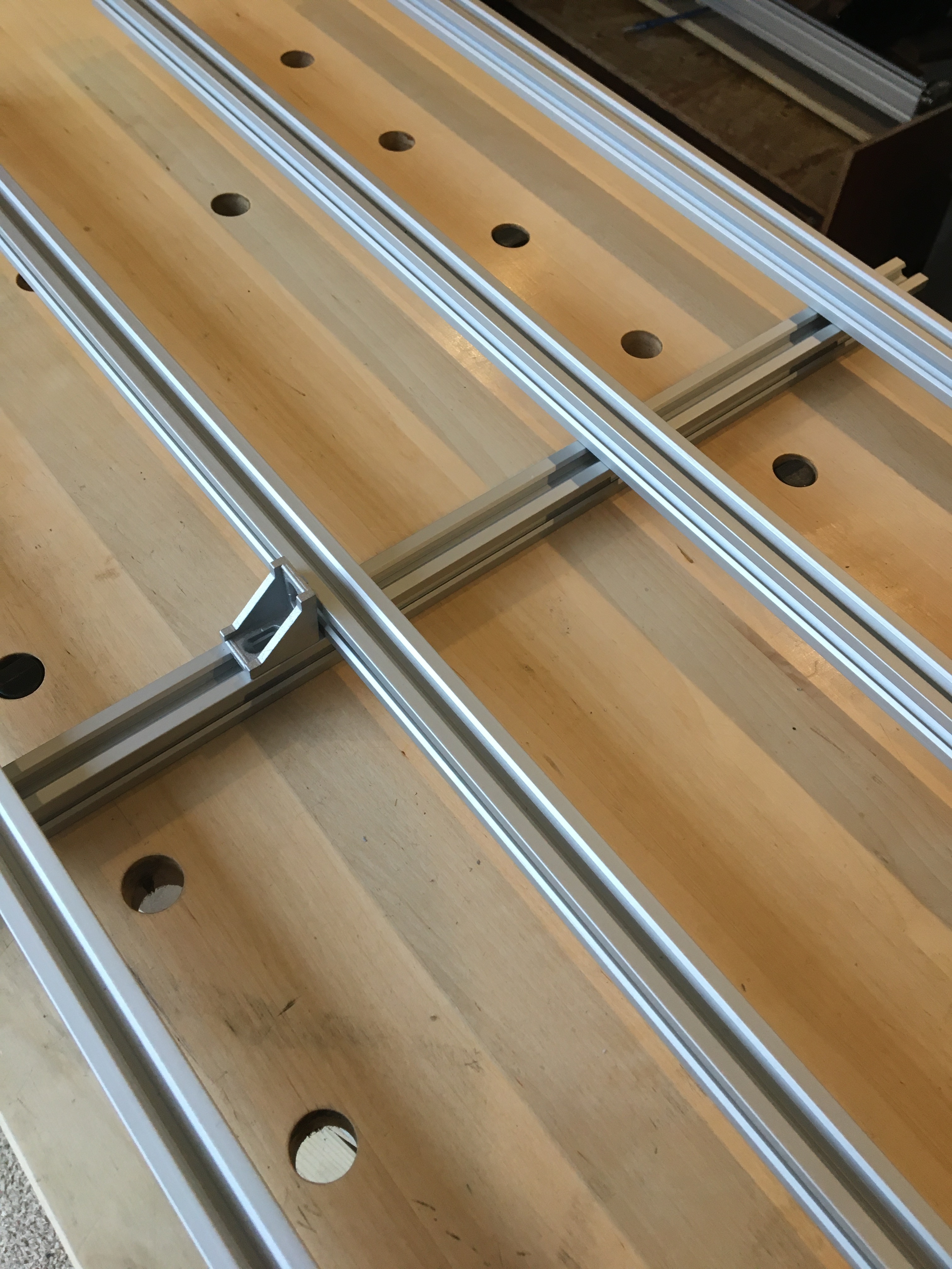
I do have some 2020 in my workshop that I’m using to make doors for my XL enclosure. I laid them out to pictorially represent the suggestion. I don’t have any low-profile right-angle mounts but hopefully the concept is clear:
The MDF slats have a center hole, but the aluminum base slats that are below the MDF going from front to rear have 3 bolt down holes each in them. I believe they are all 25mm apart. M6 with a thread pitch of 1.
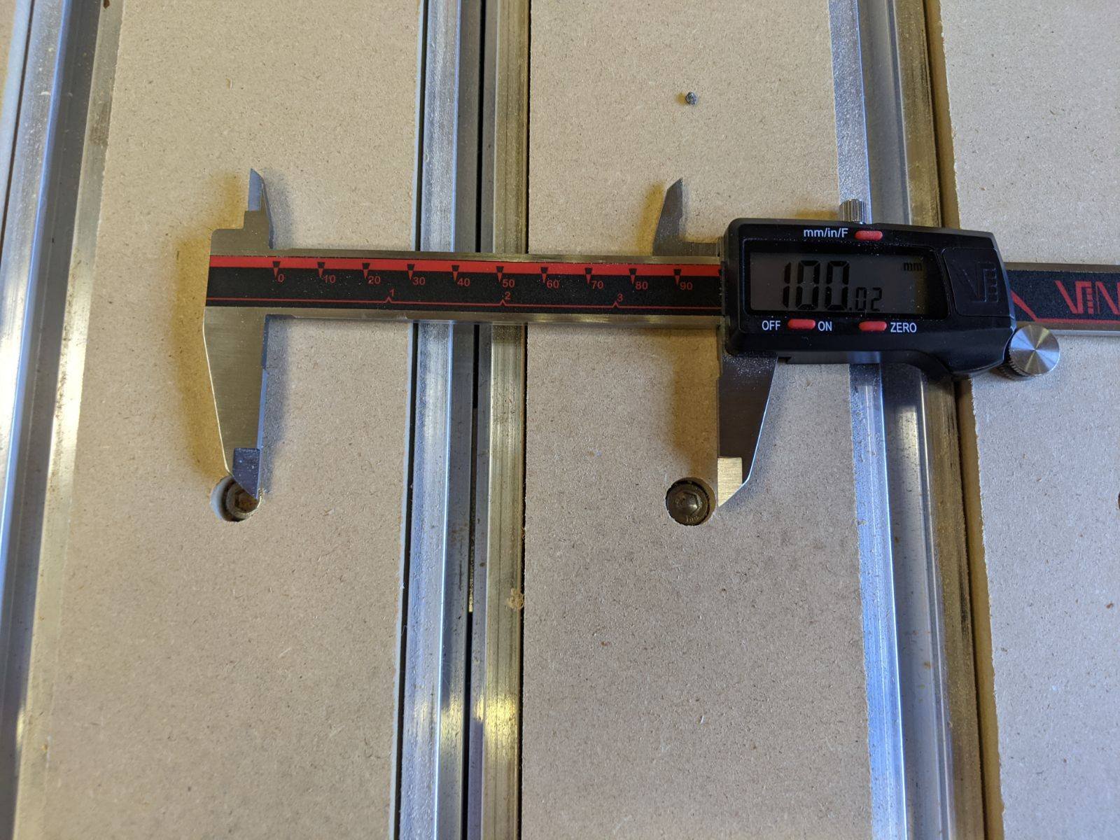
Thanks for those measurements! Sorry, I was probably a little unclear, especially on a thread for the frame. This one had the best measurement specs already, so it seemed like a good place to ask . I’m mainly interested in the spacing of the bolts holding down the MDF slats. I tried to get some accurate measurements last night, but I was under the impression my calipers had committed to full time glitch screen. Turns out they just needed a new battery lol.
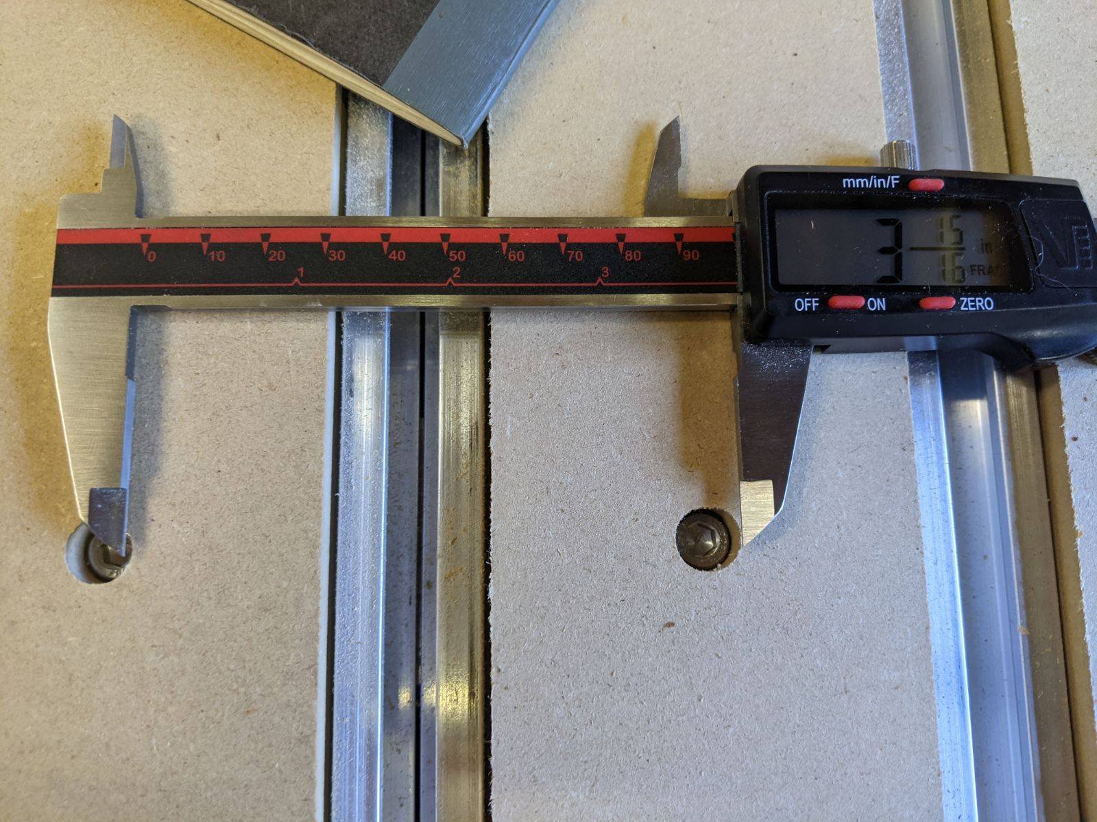
As seen in the pics, I was able to get two potential readings. The spacing looks a little off just so I could get clear photos. The 100mm felt dead on, and it consistent with @CNCInspiration’s numbers, and the general theme of the x-frame key dimensions being metric, and the y being imperial. Additionally, when not laying it flat, and using 2 hands, perfect 100.00 readings were obtained. The 3 15/16 reading wasn’t quite exact, and took a little massaging to get a reasonable fraction out of it.
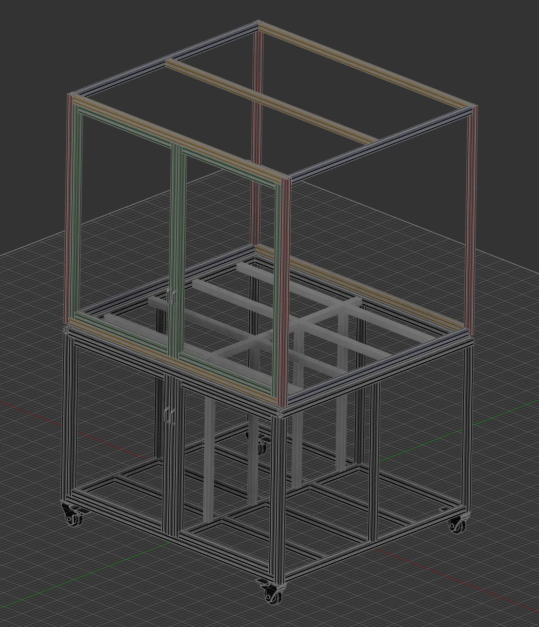
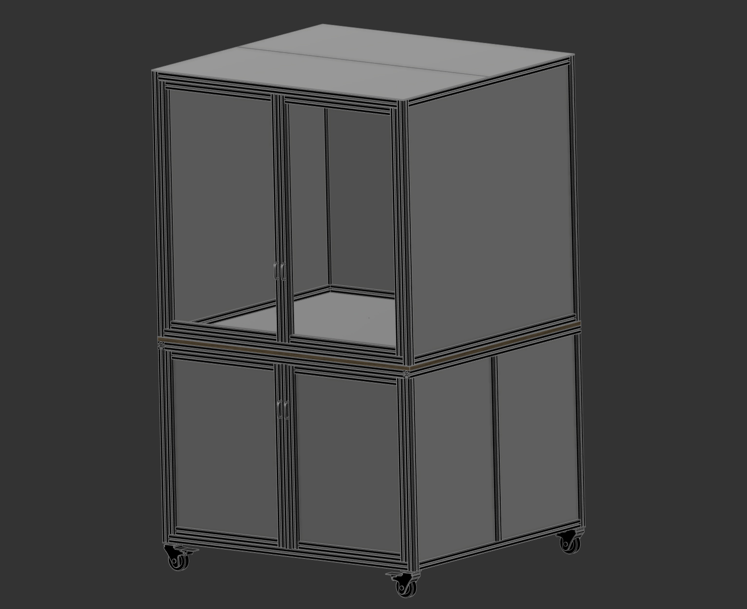
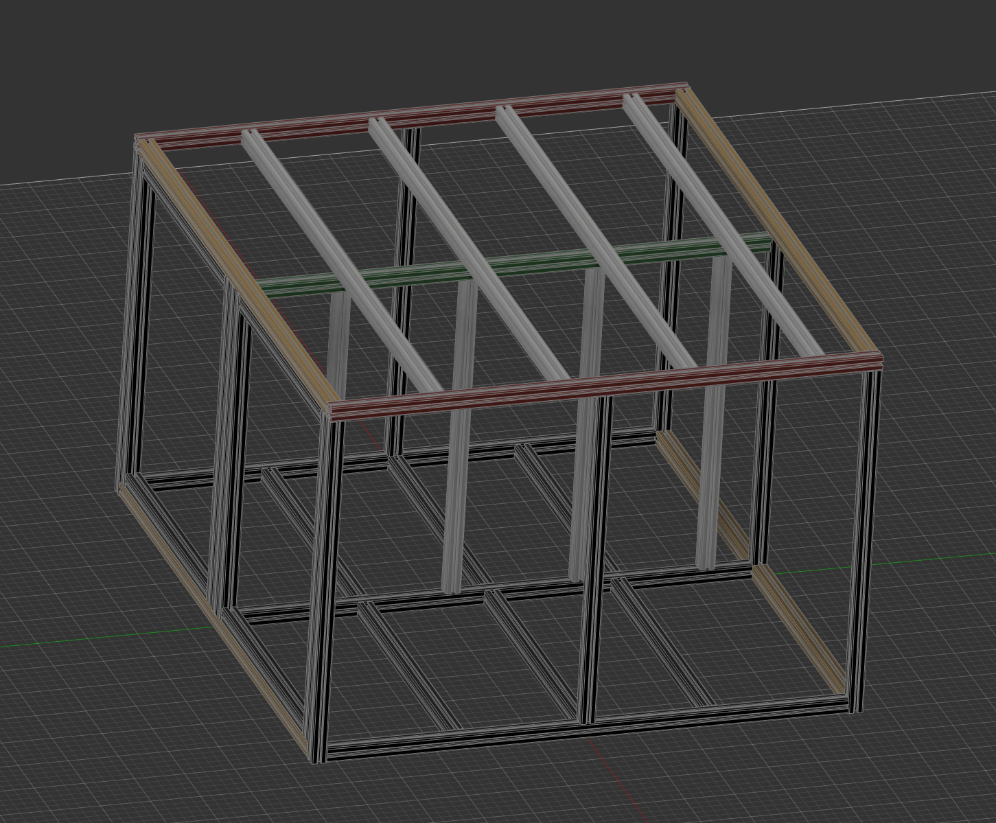
Not sure if this is still needed by anyone, but whatever. This model is incomplete and certainly not structured in the best way, but I had to do it on the fly in-between about 10 other things going on at work so don’t hate too hard! I’ve been using this, at least the hybrid table structure that is, for a more reliable way to setup jigs and work holding. Haven’t had any issues thus far and everything seems to be pretty well in the right place! Cheers!
Zip Archive with F3D and STEP file of Hybrid Table and Y Rails.